VEHICLE ELECTRIFICATION SOLUTIONS - SEMICONDUCTOR SYSTEM SOLUTIONS FOR THE NEXT GENERATION OF ELECTRIFIED VEHICLES - NXP

Page created by Pedro Williamson
 
CONTINUE READING
VEHICLE ELECTRIFICATION SOLUTIONS - SEMICONDUCTOR SYSTEM SOLUTIONS FOR THE NEXT GENERATION OF ELECTRIFIED VEHICLES - NXP
VEHICLE ELECTRIFICATION
SOLUTIONS
SEMICONDUCTOR SYSTEM SOLUTIONS FOR THE NEXT
GENERATION OF ELECTRIFIED VEHICLES
VEHICLE ELECTRIFICATION SOLUTIONS - SEMICONDUCTOR SYSTEM SOLUTIONS FOR THE NEXT GENERATION OF ELECTRIFIED VEHICLES - NXP
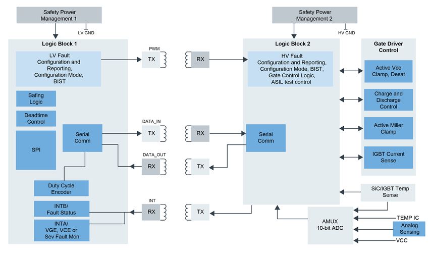
Table of Contents
Introduction.................................................................................... 3

Why NXP for Electrification?........................................................... 4

Propulsion Domain Control............................................................ 5

Battery Management Reference Platform....................................... 6

HEV/EV Power Inverter System Reference Platform....................... 7

Development Platforms ................................................................. 8

Microcontroller Hybrid Control Unit............................................... 9

Vehicle Dynamics and Safety MCUs............................................. 10

Electrified General-Purpose Nodes.............................................. 11

Power Management: Functionally Safe System Basis Chips......... 12

Battery Management Systems...................................................... 14

Battery Pressure Monitoring Sensors............................................ 15

Battery Pressure Monitoring Sensors — Features......................... 16

Motor Control: High Voltage Inverters......................................... 17

Vehicle Network Protocols............................................................ 18

NXP, Your Electrification Partner................................................... 19

NXP Product Summary................................................................. 20

SafeAssure® Functional Safety Program........................................ 21

Security Program.......................................................................... 22

Available Resources...................................................................... 23

nxp.com/electrification                                                                              2
VEHICLE ELECTRIFICATION SOLUTIONS - SEMICONDUCTOR SYSTEM SOLUTIONS FOR THE NEXT GENERATION OF ELECTRIFIED VEHICLES - NXP
INTRODUCTION                                                                              WHICH ENERGY TO USE?

BACK TO THE CHARGE                                                                        A frequent detracting argument for electric vehicles is
                                                                                          over the increased use of electricity for slow charging. The
The megatrends that have shaped our automotive industry                                   counter point to this argument is the reduction in gasoline
development over the past few years are taking on a                                       and diesel displacement and the resulting decrease in CO2
new importance with the massive societal changes we’re
                                                                                          emissions.
experiencing. With the dramatic drop in emissions during
the stay-at-home orders around the world and a broad                                      With more than 2 million in sales, electric vehicles made
consumer acceptance of changing the way we interact, the                                  up 2.6% of the global car sales in 2019—Another big step
opportunity for future mobility use cases is tremendous.                                  from the previous year.1

CONSUMER PRESSURE                                                                         CHARGING INFRASTRUCTURE

Renewed government incentives to tackle pollution and                                     The scale of the electric charging infrastructure is a
consumer interest in a greener, cleaner and safer future                                  sensitive area that hasn’t been favorable for EV adoption.
are redefining energy industry objectives and providing                                   Desperately inadequate for mass adoption, the majority of
a notable boost to the electrified vehicle market. For                                    the 7.3 million chargers1 worldwide are privately owned.
example, the subsidy program in China will now run                                        While the necessity of home-based charging is clear, the
through 2022 with an extension to the New Energy Vehicle                                  convenience and reassurance of widespread charge points
Mandate. In Europe, governments have reworked the CO2                                     are undeniable.
emissions standards.1 Meanwhile, climate change activists
                                                                                          BATTERY PACK EVOLUTION
have increased public awareness and made greener living
seem more attainable and attractive. NXP is responding to                                 Through all this, the challenge for the automotive
this global support with our vehicle electrification portfolio                            industry is to find the path to make electric vehicles more
and our “Vision Zero” goals: zero emissions, zero accidents                               profitable than ICE models. The sticking point here is the
and zero time wasted.                                                                     balance between the size and cost of the battery pack
                                                                                          and the consumer acceptance for the vehicle range on
                                                                                          a single charge. The unit cost of the battery pack and
                                                                                          manufacturing capacities are key to the expansion of the
                                                                                          electric vehicle market.

                                                                                          https://www.nxp.com/company/blog/back-to-the-
                                                                                          charge:BL-BACK-TO-THE-CHARGE

 5 moments of truth for EV adoption

  Iea. “Global EV Outlook 2020 – Analysis.” Accessed September 15, 2020. https://www.iea.org/reports/global-ev-outlook-2020.
1 

nxp.com/electrification                                                                                                                             3
VEHICLE ELECTRIFICATION SOLUTIONS - SEMICONDUCTOR SYSTEM SOLUTIONS FOR THE NEXT GENERATION OF ELECTRIFIED VEHICLES - NXP
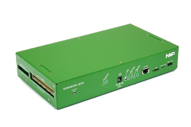
WHY NXP FOR ELECTRIFICATION?
       Accelerate to zero emissions with NXP’s electrification solutions. From battery
       management to propulsion Domain control, our aim is to simplify the electrification
       transition. NXP delivers an electrified system solution, incorporating optimal performance,
       robust functional safety, and power management features that automakers and developers
       require for their next generation of vehicles.

       Our automotive electrification products feature

       • High-performance microprocessors.
       • Scalable functional safety
       • MCUs with associated power management ICs and system basis chips (SBCs)
       • In-vehicle networking components for CAN, LIN, FlexRay™ and Ethernet
       • Battery cell controller and battery management solutions
       • Electric motor driver solutions, based on advanced functional safety IGBT gate drivers
       • Enablement platforms, reference designs and evaluation boards
       • Worldwide presence and support
DIAGRAM TITLE
       • Automotive robustness

                                                                     AC-DC
                                                                     Charger
               Major Components
                                                                     ~                          Motor Control         Motor(s)
                Battery Management                       AC
                                                                          =                      =
                      System                                                                    =                       M
                                                         DC                                           ~               MM
                    Motor Control                                                                    ~
                    (HV inverters)
                                                           BMS
                                                                               Hybrid Control
                 Hybrid Control Unit                      HV                    Unit (HCU)
          (Torque/Energy Management & Optimization)
                                                         Li-ion                                                  48 V or
                                                         Battery                                                 > 60 V (e.g., 400 V)
                   48 V eMachine                                                  DC-DC
                 (BSG, ISG, HVAC)                                                =                        48 V and HV
                                                           BMS                                              Modules
                   DC-DC Voltage                            LV                         =
                  Domain Converter                       lead-acid
                                                         or Li-ion
                                                                                            12 V
                  Onboard Charger                         Battery
                                                                                                           12 V-Bus
                  AC-DC converter                                                                          Modules

       nxp.com/electrification                                                                                                     4
VEHICLE ELECTRIFICATION SOLUTIONS - SEMICONDUCTOR SYSTEM SOLUTIONS FOR THE NEXT GENERATION OF ELECTRIFIED VEHICLES - NXP
PROPULSION DOMAIN CONTROL                                                                      SUPPORTED DEVICES
     The hybrid/electrical control unit is the brain of the                                         • FS66: functionally safe multi-output power supply
     powertrain control for hybrid or electric vehicles. It will                                      integrated circuit
     control the power distribution, energy storage, engine
                                                                                                    • S32S24: Based on the Arm Cortex-R52 core, the S32S24
     and motor. As such, it is key for enhancing the efficiency
                                                                                                      microcontroller is designed for automotive vehicle
     of the xEV powertrain.
                                                                                                      dynamics, domain control and safety coprocessor
                                                                                                      applications. It offers support for the highest levels
     BENEFITS
                                                                                                      of automotive safety and with more than 7x the
     • NXP S32S/E: market leader for propulsion domain                                                performance of the previous generation of NXP devices,
       architecture with automotive ASIL D compute                                                    provides the performance headroom to manage the
       performance                                                                                    transition to advanced electrification and autonomous
     • Virtual automotive ECU development platform available                                          vehicle applications.
                                                                                                         Reference platform part number: S32EDEVPL
     FEATURES
     • Executes multiple applications, including hybrid electric
       control with advanced algorithms, all under hypervisor
     • Energy and thermal management
     • Regenerative braking
     • Battery states (charge, health, function) management
        – Advanced algorithms (torque vectoring, A-ECMS, etc.)
     – Inter-domain communication, acts on ADAS domain
      HYBRID
       messagesAND  EV POWERTRAIN BLOCK DIAGRAM
                 (GLOSA)
HYBRID AND   EV POWERTRAIN    BLOCK DIAGRAM

                                                                                                                        External Inputs
                                                                                                          External Inputs
                                                                                                                       (IVN & Gateway)
                                                                                                         (IVN & Gateway)
                                                                                              IVN
                                                                                IVN

                                                          Electric Motor Control                                        Hybrid Vehicle                                Internal Combustion Engine
                                            Electric Motor Control
                                                            one for each motor                            Hybrid VehicleControl Unit                    Internal Combustion Engine
                                                                                                                                                                               Control Unit
                                              one for each motor                                           Control Unit                                          Control Unit

                                                   Functional                                              Functional                                             Functional
                                     Functional      Safety                   MCU           Functional      Safety                    MCU          Functional       Safety                 MCU
                                       Safety         SBC     MCU                             Safety         SBC      MCU                            Safety          SBC     MCU
                                                                                                                                                         IVN

                                        SBC                                                    SBC                                                    SBC
                                                                                                                                             IVN

                                                                   Inverter
                                                     Inverter
                                                                 Isolated                                           DC/DC Converter
                                                    Isolated   High-Voltage                              DC/DC Converter
                                                  High-Voltage Gate Driver                                 Functional
                                                  Gate Driver                               Functional       Safety                   MCU
                                                                                              Safety          SBC     MCU
                                                                                                                                                                     Input Signal            Output
                                                                 High-Voltage                  SBC
                                                                                                                                                     Input Signal    and Sensor Output       Drivers
                          Battery                 High-Voltage      IGBT/                                                                            and Sensor        Interface Drivers
               Battery  Management                   IGBT/         MOSFET
                                                                                                                                     Intelligent       Interface
             Management   System                    MOSFET
               System                                                                                                 Intelligent     Battery
                                                                                                                       Battery        Sensor
                                                                                                                       Sensor

                                                                 High-Voltage                                                                                                Internal Combustion
                                                  High-Voltage Electric Motor                                                                                   Internal Combustion Engine
                                                                                                                                    12 V Battery
                                                  Electric Motor                                                                                                      Engine
                                                                                                                     12 V Battery
                                                                                      IVN
                                                                        IVN

              NXP Technology
   NXP Technology

    HEV Powertrain Control Block Diagram

     nxp.com/electrification                                                                                                                                                                       5
VEHICLE ELECTRIFICATION SOLUTIONS - SEMICONDUCTOR SYSTEM SOLUTIONS FOR THE NEXT GENERATION OF ELECTRIFIED VEHICLES - NXP
BATTERY MANAGEMENT REFERENCE PLATFORM

 BATTERY MANAGEMENT REFERENCE DESIGN FOR                             REFERENCE DESIGN KIT CONTENTS
 HIGH VOLTAGE BMS                                                    • Evaluation board
 The RD33771CNTREVM provides a solution for a                        • Schematic, layout and Gerber files
 centralized and distributed architecture for lithium-ion
 battery management in automotive applications. This                 • Quick start guide
 board allocates four MC33771C devices controlled by                 • User manual
 one MCU. The MCU could be bypassed and stacked to
                                                                     • Software drivers
 a long daisy chain for a flexible BMS architecture. BCC
 can measure lithium batteries having 7 to 14 cells each.            SUPPORTED DEVICES
 The BCCs communicate by TPL daisy chain or capacitor
                                                                     • MC33771C: 14-Channel Li-ion Battery Cell Controller IC
 Isolation. The MCU is supplied by an SBC that is powered
 by a 12 VDC power source.                                           • MC33664: isolated network high-speed transceiver
                                                                     • S32K1: microcontrollers for general purpose
 KEY FEATURES
                                                                     • UJA1169TK: Mini High-Speed CAN System Basis Chip
 • 56-cell sense inputs with low pass filter
                                                                     • Reference platform: RD33771CNTREVM
 • 24 external temperature sensors
 • Integrated cell balancing resistors
 • Daisy chainable boards
BMS BLOCK DIAGRAM

                                                                                        Hybrid and Electric
                                                                                        Vehicle Powertrain

    12 V Lead-Acid BMS       14 V Li-ion BMS      48 V Li-ion BMS

             IVN                       IVN               IVN                                   IVN
                                                                                                                High-Voltage Battery
                                                                     High-Voltage BMS                              Junction Box

           Battery              Functional           Functional       Functional                                       Functional
           Sensor               Safety SBC           Safety SBC       Safety SBC                                       Safety SBC

                                      MCU               MCU              MCU                                              MCU

                                                      Isolated          Isolated             Isolated
                                                   Communication     Communication        Communication

                                Battery Cell         Battery Cell     Battery Cell         Battery Sensor            Smart Switches    Load Switching
                               Controller AFE       Controller AFE   Controller AFE             AFE

         12 V Lead                  14 V Li-ion      48 V Li-ion      High-Voltage      Switches, Pre-charger
                                                                                                                       Cooling Fan,     HV Battery
         Acid Battery                Battery          Battery            Battery           Stack Voltage,
                                                                                                                         Pumps          Contractors
                                                                                              Current

   NXP Technology        Optional

 Battery Management System Reference Platform Solution Block Diagrams

 nxp.com/electrification                                                                                                                                6
VEHICLE ELECTRIFICATION SOLUTIONS - SEMICONDUCTOR SYSTEM SOLUTIONS FOR THE NEXT GENERATION OF ELECTRIFIED VEHICLES - NXP
HEV/EV POWER INVERTER SYSTEM REFERENCE PLATFORM

HEV/EV POWER INVERTER SYSTEM REFERENCE                                             BENEFITS
PLATFORM                                                                           • ASIL C/D compliancy with small, compact 9 IC
The xEV power inverter system solution is a small                                    system footprint
footprint 400 V ASIL D 100 kW power inverter platform                              • Robust fail-silent SBC with operation from 36 V
which includes:                                                                      down to 2.7 V
• MPC5775E: secure multi-core 32-bit lockstep MCU                                  • Secure multicore 32-bit lockstep MCU with eTPU
  with software resolver                                                             and SW RDC
• FS65: Grade1/Grade0 Safety SBC, fit for ASIL D,                                  • Functional safety case and enablement software
  with two fail-safe outputs for motor control safety                                with API
  management
                                                                                   • < 2 µs iSense-compatible 2-level IGBT OC protection
• GD3100: advanced isolated IGBT/SiC gate driver                                     with soft shutdown
  with < 2 µs overcurrent protection
• TJA1051: redundant CAN bus interface with                                        FEATURES
  low-power standby                                                                • Efficiently drives 100 kW 3-phase motor from
• Enablement software with API and functional safety case                            400 V supply
                                                                                   • Integrated galvanic signal isolation in IGBT/SiC
                                                                                     gate drivers
                                                                                   • Redundant CAN bus interface with low-power standby
                                                                                   • Primary and backup battery inputs with no negative
                                                                                     gate driver supply
                                                                                   • Supported by S32DS SDK with MCAL drivers

                                                                                                                 HVBAT
                                                                                         DC/DC
                                                                                          LV HV                               Link
                                                                                                                            Capacitor
                                  FAIL SAFE 2                         To HV
                                                                    Disconnect
                           VAUX
 VBAT

                                  FAIL SAFE 1

        IGN    FS6500
               System             VMCU
                                                                        SPI
        CAN     Basis                                                                    GD3100                                         Motor
                Chip                                                    Fault          Gate Driver
                                                                                                                 IGBT
                                  SPI                                                     w/ HV
                                                                                                                  x6
                                                                        PWM             Isolation
                                  Fault                                                      x6
               Fail-Safe
               Circuitry          RST
                                                MPC5775E
                                                  MCU

                                                                    Voltage/Temp
                                                                        Sense
              TJA1051T
        CAN                   CAN
                 CAN
              Interface
                                                                                                 Current Sense

                                                    Software
                                                  Resolver to                                    Resolver I/O
                                                Digital Converter                                                                       Resolver

Hybrid and EV Powertrain Block Diagram

nxp.com/electrification                                                                                                                            7
DEVELOPMENT PLATFORMS
In addition to our development platforms, evaluation boards and tools are available to help accelerate your
electrification designs.

                            EVB NAME                                                               DESCRIPTION

                                                  GreenBox, advanced performance, peripherals and multicore Arm® environment for HEV and EV development
                    S32EDEVPL
                                                  with peripheral board for HEV and ICE applications
                                                  Dual 3-phase PMSM development kit with MPC5643L microcontroller; suitable for applications requiring 2 PMSM
                    MTRCKTDPS5643L
                                                  motors, such as active suspension or electric powertrain
                                                  MPC5775B MCU targets industrial and automotive battery management systems (BMS); the MPC5775E targets
                    MPC5775BE-416DS adapter       HEV/ EV inverter control systems that require advanced performance; eTPU-based timer system and ISO 26262/
                                                  IEC 61508 functional safety support up to ASIL D
                                                  For automotive engine control applications that require advanced performance, timing systems and functional
                    MPC5775BE-516DS adapter
                                                  safety capabilities
HV BMS - Cell
Supervision                                       Offers dual e200z4 lockstep cores, motor control, safety and communication interfaces to facilitate a complete
                    DEVKIT-MPC5744P
Circuit (CSC)                                     safety/ chassis solution for motor control applications
                    RD33771CNTREVM                Battery Management Reference Design for High Voltage BMS
                    RD33771CDSTEVB                14-channel Li-Ion BCC with isolated daisy chain interface with MC33771C BCC
                    FRDM33771CSPEVB               14-channel high performance Li-Ion BMS with SPI interface using MC33771C BCC
                    FRDMDUAL33664EVB              Dual TPL interface between MCU and isolated network with loopback using MC33664 device
                    FRDM33771BTPLEVB              14-channel Li-ion battery cell controller with isolated daisy chain interface using MC33771B BCC
                    FRDM33664BEVB                 TPL interface between MCU and isolated network using MC33664 device
                    FRDM33772BTPLEVB              6-channel Li-Ion BCC with isolated daisy chain interface using MC33772B BCC
                                                  High Voltage Battery Junction Box (BJB) RD with functional safety, voltage, current, temperature and insulation
HV BMS - Battery RD33772BJBEVM                    measurement function
Junction Box
                 FRDM33772BTPLEVB                 6-channel Li-Ion BCC with isolated daisy chain interface using MC33772B BCC
(CSC)
                 FRDM33664BEVB                    Transceiver physical layer (TPL) interface between MCU and isolated network using MC33664 device
HV-BMS Battery      MPC5775B-EVB                  Low-cost development boards engineered for battery applications
Management
Unit                RDVCU5775EVM                  Reference design for high-voltage BMS and vehicle control unit integration for ASIL D applications

                    RD33771-48VEVM                48 V mild hybrid auxiliary battery management system reference design
                    FRDM33771CSPEVB               14-channel high performance Li-Ion BMS with SPI interface using MC33771C BCC
48 V BMS
                    FRDM33771BSPIEVB              14-channel Li-ion battery cell controller with SPI interface using MC33771B BCC
Solutions
                    FRDM33771BTPLEVB              14-channel Li-ion battery cell controller with isolated daisy chain interface using MC33771B BCC
                    FRDM33664BEVB                 Transceiver physical layer (TPL) interface between MCU and isolated network using MC33664 device
                    NEWTEC-NTBMS                  12 V battery management system for Li-Ion batteries supporting ASIL C safety levels
                    RD9Z1-638-4LI                 4-Cell Li-Ion BMS with high EMC performance and CAN interface using MM9Z1_638 sensor
12 V BMS            RD9Z1-638-12V-C               12 V lead-acid BMS with high EMC performance with CAN interface using MM9Z1_638 sensor
Solutions           RD9Z1-638-12V                 12 V lead-acid BMS with high EMC performance with LIN interface using MM9Z1_638 sensor
                    FRDM33772BSPIEVB              6-channel BCC for Li-Ion battery applications with SPI interface using MC33772B BCC
                    KIT9Z1J638EVM                 Battery sensor for current, voltage and temperature with CAN/LIN interface using MM9Z1_638 sensor
                    BATT-6EMULATOR                6-cell battery pack to supply MC33772 EVBs—emulates a multi-cell battery pack
                    BATT-14CEMULATOR              14-cell battery pack to supply MC33771C EVBs—emulates a multi-cell battery pack
                    BATT-14EMULATOR               14-cell battery pack emulator made to supply MC33771B BCC EVBs
                    BATT-14EXTENDER NE            Allows for the connection up to four evaluation boards using only one single battery emulator
General Tools
                    BATT-14AAAPACK                A configurable battery pack that can be used to supply the MC33771 or MC33772 evaluation boards.
                                                  Half-bridge evaluation kit populated with two MC33GD3100 single-channel IGBT gate drive devices on a half-
                    FRDMGD3100HBIEVM
                                                  bridge evaluation board
                    FRDM-GD3100EVB                Half-bridge evaluation board for GD3100

                                Battery
                                Management
                                System
                                                        Traction
                                                        Motor              Hybrid Vehicle
                                                                           Control Unit                         NXP GreenBox
                                                                                        Traction             Development Platform
                                                                                        Motor
                                                                                                              Target Applications

        Traction
          Motor

                   Integrated
                      DC-DC                                                                                            Internal
                   Converter                                                                                           Combustion
                                                                                                                       Engine
                                             Traction
GreenBox Platform                              Motor

nxp.com/electrification                                                                                                                                             8
MICROCONTROLLER HYBRID CONTROL UNIT
  The hybrid control unit (HCU) is a core control component for hybrid and electric vehicles. It uses input signals to
  calculate and manage output parameters such as engine power or motor torque.

  S32S24 SAFETY MICROCONTROLLER
  The S32S24 is an Arm-R52-based microcontroller for automotive vehicle dynamics, domain control and safety
  coprocessor applications. It offers support for the highest levels of automotive safety and with more than 7x the
  performance of the previous generation of NXP devices, provides the performance headroom to manage the transition
  to advanced electrification and autonomous vehicle applications.

  FEATURES AND BENEFITS
  • 4 x Arm-R52 cores in lockstep (8 cores total), operating                        • Advanced safety functionality and fault recovery to
    at 800 MHz                                                                        support ASIL D applications
  • Large integrated flash memory (up to 64 MB)                                     • Hardware security engine supporting public and private
                                                                                      key encryption
  • On-the-fly, over-the-air update capability with zero
    processor downtime                                                              • AEC-Q100 Grade 1 device with support from -40 °C
                                                                                      to 150 °C (junction)
S32S247 HIGH PERFORMANCE SAFETY DEVICE

            Memory                                                             CPU Platform                                                System

       4 MB SRAM with ECC                                                                                                            FCCU and MBIST/LBIST
                                    Arm-Cortex-R52               Arm-Cortex-R52          Arm-Cortex-R52             Arm-Cortex-R52
                                                                                                                                        PLL and FMPLL
     512 KB Data Flash Memory
                                 Arm®-Cortex®-R52               Arm-Cortex-R52          Arm-Cortex-R52           Arm-Cortex-R52
             with ECC                32 KB     32 KB              32 KB     32 KB         32 KB     32 KB          32 KB     32 KB
                                    I-cache D-cache              I-cache D-cache         I-cache D-cache          I-cache D-cache        2 x Safe DMA
                                  32 KB      32 KB             32 KB      32 KB        32 KB      32 KB         32 KB      32 KB
   16 MB Flash Memory with ECC   I-cache D-cache              I-cache D-cache         I-cache D-cache          I-cache D-cache
                                      3x 32 KB TCM                 3x 32 KB TCM            3x 32 KB TCM             3x 32 KB TCM      Debug and Trace Unit

                                  3 x 32 KB TCM                3 x 32 KB TCM           3 x 32 KB TCM             3 x 32 KB TCM
          Networking
       8 x FlexCAN with FD                                        Neon™                                                Neon

            1 x Zipwire                                                                                                                Motor Control

         2 x Gbit Ethernet
                                 Lockstep cores               Lockstep cores         Lockstep cores            Lockstep cores
                                                                                                                                         4 x SAR ADC
     2 x Dual-Channel FlexRay
                                        Serial Communication                                                                             2 x FlexPWM
                                                                                                    Safe Interconnect
           Security
                                                   6 x DSPI                                                                                 2 x CTU
        Hardware Security                                                                      Timers and General I/O
          Engine (HSE)                            6 x LINFlex                                                                             4 x eTimer

                                                                                                        2 x eMIOS
       Asymmetric Hardware                        2 x PSI5-S
           Accelerators
                                                   1 x PSI5
                                                                                                       2 x FlexTimer
       Symmetric Hardware
          Accelerators
                                                  16 x SENT                                                                          Memory Interface

       64 KB Secure SRAM                                                                               1 x SAR ADC                          uSDHC
                                                    5 x I2C

  S32S Block Diagram

  nxp.com/electrification                                                                                                                                    9
VEHICLE DYNAMICS AND SAFETY MCUs

MPC5744P, MPC5777C, MPC5775B AND MPC5775E FOR BATTERY MANAGEMENT SYSTEMS
AND INVERTER APPLICATIONS
These microcontrollers target automotive and industrial battery management and inverter applications that
require advanced performance, security and ASIL D support.

FEATURES AND BENEFITS
• High-performance cores with advanced programmable motor control timers and analog modules
• Functional Safety ISO 26262 targeting ASIL D with lockstep cores, ECC, temperature and voltage sensors,
  clock monitoring, and fault collection unit
• Hardware security module (CSE) with encryption and decryption, secure boot and key storage; pre-programmed
  firmware simplifies production
• Communication peripherals via CAN FD, Ethernet, SPI, LIN
• Software enablement with AUTOSAR® MCAL, S32 Design Studio

                          Traction                                                 Internal
        Battery
                            Motor                                             Combustion
    Management
                          System                                            Engine Control
        System

                         IGBT                                              Low-Voltage           Hybrid Vehicle
                    Gate Driver                                                Battery           Control Unit
                                                                           Management
                                                                               System

MPC5744P, MPC5777C, MPC5775B and MPC5775E Automotive Applications

nxp.com/electrification                                                                                           10
ELECTRIFIED GENERAL-PURPOSE NODES

THE SCALABLE S32K1 FAMILY: ACCELERATED DESIGN                            RUNTIME SOFTWARE
TIME, LOW-POWER PERFORMANCE                                              • Automotive-grade NXP software development kit (SDK)
• Performance and integration with future-proof designs                  • NXP middleware e.g., core self test, LIN stack
• Automotive-grade software with minimized complexity                    • AUTOSAR 4.0 and 4.2 MCAL
• Broad portfolio allows maximized reuse                                 • FreeRTOS

S32K FUNCTIONAL SAFETY SOFTWARE                                          • Bootloader

• Cortex-M Core Self-Test Library: Structural Core                       SOFTWARE DEVELOPMENT TOOLS
  Self-Test Library (SCST) is a safety measure against
  permanent faults in the cores                                          • IAR, GHS and GNU toolchains

• Developed for detecting hardware permanent faults                      • Full-featured, no-cost development platform (S32 DS)
  in a core by means of executing machine op-codes                       • FreeMASTER
  with fixed set of operands and comparing their
  execution results                                                      APPLICATION SPECIFIC

• This library is considered as Safety Element out of                    • Motor control
  Context and was developed according to ASIL B                          • Touch sensing
• SCST library provides tests to achieve the claimed                     • Secure communication
  diagnostic coverage (analytically estimated)
                                                                         • Wireless charging
HARDWARE PLATFORM                                                        • Near-field communication
• Low-cost development board compatible to
  Arduino® shields
• Onboard debugger and system basis chip

BLOCK DIAGRAM TITLE CAPS AT 20PT.

                   S32K11x MCUs                        Common Features                                  S32K14x MCUs
         S32K116                     S32K118                AEC-Q100              S32K142         S32K144         S32K146        S32K148
          MCU                         MCU                                          MCU             MCU             MCU            MCU
           Arm® Cortex®-M0+ Core @ 48 MHz              CSEc Security Module                    Arm Cortex-M4F Core @ 112 MHz

       128 KB Flash                 256 KB Flash                                256 KB Flash    512 KB Flash     1 MB Flash     2 MB Flash
                                                         ASIL B Compliant
        16 KB SRAM                  24 KB SRAM                                   32 KB SRAM     64 KB SRAM 128 KB SRAM 256 KB SRAM
                                                       Low-Power Operating
                                                        Modes & Peripherals
       up to 42 I/Os                up to 58 I/Os                                       up to 89 I/Os           up to 128 I/Os up to 156 I/Os
                                                              Flex I/O
                                                                                                           16-ch. eDMA
                       4-ch. eDMA
                                                               MPU              2 x FlexCAN     3 x FlexCAN      3 x FlexCAN    3 x FlexCAN
                                                                                 with 1 x FD     with 1 x FD      with 2 x FD    with 3 x FD
                1 x FlexCAN with 1x FD
                                                               JTAG                                               2 x 24-ch.    2 x 32-ch.
                                                                                   2 x 16-ch. 12-bit ADC
                                                                                                                  12-bit ADC    12-bit ADC
    1 x 13-ch. 12-bit ADC      1 x 13-ch. 16-bit ADC         FlexTimer
                                                                                                 LQFP-64
                                                                                                                                 LQFP-176
                                                               SDK                              LQFP-100
          QFN-32                      LQFP-64
                                                                                                                 MAPBGA-100
                                                            NFC Stack
                        LQFP-48
                                                                                                                          LQFP-144
                                                          ISELED Driver                                                            ENET

                                                                                                                                 QuadSPI
                                                       AUTOSAR® MCAL/OS
                                                                                                                                 ETM Trace
                                                       S32 Design Studio IDE                                                         SAI

S32K General-Purpose Microcontoller Common Features

nxp.com/electrification                                                                                                                         11
POWER MANAGEMENT: FUNCTIONALLY SAFE SYSTEM BASIS CHIPS

FS45 AND FS65 GRADE 1 AND GRADE 0 SAFETY POWER SYSTEM BASIS CHIPS
The family of FS45 and FS65 safety SBC chips provides power management to MCUs by the optimization of energy
consumption through DC-DC switching regulators, linear regulators and ultra-low-power saving modes.

FEATURES AND BENEFITS
• Physical and electrical independence to target                 • Configurable RSTb activation provides more
  ASIL B or D applications                                         system availability
• Power management monitoring unit (UV/OV/OC)                    • Redundant system fail-safe enabler
• Analog and digital built-in self-test to minimize              • Second fail-safe pin to assert safety path with
  latent faults                                                    configurable delay after failure
• Redundant reference and supply to reduce common                • Long-duration timer (from seconds to months) to
  cause failure                                                    simplify RTC function and reduce costs
• VCORE external monitoring                                      • Tracker rail, short circuit to battery proof, to supply
                                                                   external ECU loads (sensors, etc.)
• FCCU: fault collection control unit
                                                                 • FCRBM: Feedback Core Resistor Bridge Monitoring
• Monitor lock-step MCUs

   FS65 and FS45                                                                                                   MCU
                              VCORE Regulation        VCORE
                               SMPS or Linear                                                               VDD_LV (1.2 V)
                                                                   Redundant
                                                      Resistor                       FCRBM
                                                                    Resistor
                                                       Bridge
                                                                     Bridge

                              VCCA Regulation          VCCA
                                                                                                            VDD_HV ADR
                                   Linear

                              VAUX Regulation          VAUX                Ext. IC
                                                                                                                   ADC
                                   Linear                                 (sensor)

                                                      IO(4)
                                                                                                            GPIO
                                                      IO(5)
                                     I/Os                                                                   GPIO
                                  Interface           IO(2)                                  FCCU_F(0)
                                                      IO(3)                                  FCCU_F(1)             FCCU

                      Fail Safe Machine
                   Fail Safe Stable Machine
                I/O Monitoring (FCCU & Ext. IC)
                                                      SPI 4
                          Watchdog                                                                                 DSPI

                                                      RSTB
 FB_core
 FCRBM             Voltage           Fail-Safe        FS0B                                                     GPIO or
    VPRE          Supervisor          Output                                                                  FCCU_F(0)
    VAUX        (OV and/or UV)        Drivers
                                                      FS1B
    VCCA
                                                                          Safety
                                                                          Switch

FS65 Functionally Safe System Basis Chip Block Diagram

nxp.com/electrification                                                                                                      12
POWER MANAGEMENT: FUNCTIONALLY SAFE SYSTEM BASIS CHIPS
     The FS66 is an automotive, functionally safe multi-output power supply integrated circuit. It’s focused on powertrain,
     safety and chassis applications and is the primary companion chip of the S32S2 microcontroller.

     FEATURES
     • 60 V DC maximum input voltage fits for 12 V and             • Standby OFF mode with very low sleep current (
BATTERY MANAGEMENT SYSTEMS                                Diagnosis and functional safety supporting ISO 26262
                                                          with single chip
MC33771 AND MC33772 REV C BATTERY CELL
CONTROLLER SOLUTION                                       • Designed to support ISO 26262 up to ASIL D safety
                                                            system
Battery topology flexibility
                                                          • Sleep mode OV/UV and temperature monitor
• Scalable software- and hardware-compatible BMS
  solution supporting 3 to >800 cells per daisy chain     • Detection of internal and external faults, i.e., open lines,
                                                            shorts, and leakages​
• MC33771 (7 to 14 cells) and MC33772 REV C (3 to 6
  cells) fully compatible                                 • Integrated balancing diagnostics

• Supporting centralized, distributed daisy chain,        Automotive robustness
  distributed CAN                                         • ESD, EMC; Hot Plug, AEC-Q 100
High integration level                                    • Temp range: -40 °C to 105 °C​
• Synchronized on-chip current sensor                     • Operational low-power mode
• Synchronized on-chip coulomb counter
• Integrated passive balancing up to 300 mA per channel
• 4.0 Mbit/s SPI or isolated 2.0 Mbit/s differential
  communication with transformer
• Averaging of cell voltage measurement
                                                                                  MC33771/2
Lifetime guaranteed high accuracy
                                                                              7 Temperature
• ± 0.8 mV cell voltage measurement error                                     3~ 14 Cell VSense
                                                                              3~ 14 Cell Balancing
• ± 0.5% total stack voltage measurement ​
• ± 0.5% integrated current sensor gain error

                                                                                                      Daisy Chain
                                                                                                     Communication
                                                                                                     up to 63 nodes

                                                                                   MC33771/2
                                                                                                     Battery Pack Controller
                                                                              7 Temperature               Low Voltage
                                                                              3~ 14 Cell VSense
                                                                              3~ 14 Cell Balancing            MC33664
                                                                              Current Sense

                                                                                                            SPI1         SPI2

                                                                                                                   MCU

                                                          MC33771 Battery Cell Controller Solution Block Diagram

nxp.com/electrification                                                                                                         14
BATTERY PRESSURE MONITORING SENSORS                                  • Capacitance to voltage converter with anti-aliasing filter

FXPS7250D4: Absolute Pressure Sensor                                 • Sigma delta ADC plus sinc filter

• Absolute pressure range: 20 to 250 kPa                             • 800 Hz or 1000 Hz low-pass filter for absolute pressure

• Automotive robustness                                              • Small package suitable for PCB integration

  – Redundant pressure transducers enable embedded                     – Lead-free, 16-pin QFN 4x4x1.98mm with
    self test                                                            wettable flank

  – Common-mode and digital self test for transducer                   – Pressure sensor protected by chemical-resistant gel
    and signal chain verification                                    • Analog version output available
  – Digital self test
                                                                     Current solution FXPS7250x or FXPS165D
  – Operating temperature range: –40 °C to 130 °C
                                                                     • Absolute pressure range:
  – AEC-Q100 Grade 1 compliant
                                                                       – 20 kPa to 250 kPa or 60 kPa to 165 kPa
• I2C compatible serial interface
                                                                       – Calibrated Pressure and Temperature measurements
  – Slave mode operation
                                                                     • I2C, SPI or Analog output interface
  – Standard mode, fast mode, and fast-mode
                                                                     • Automotive robustness
    plus support
                                                                       – Redundant pressure transducers enable
• 32-bit SPI compatible serial interface
                                                                         embedded self test
• Secure and fast data communication
                                                                       – Common-mode and digital self test for transducer
  – 12-bit data for absolute pressure                                    and signal chain verification
  – 8-bit data for temperature                                         – Qualified to AEC-Q100 Grade 1
  – 2-bit basic status and 2-bit detailed status fields                – Operating temperature range: –40 °C to 130 °C
  – 3, 4, or 8-bit configurable CRC                                    – QFN 4 x 4 x 1.98 mm, 16 pins, 0.8 mm pitch

             VCC
                                                                                          VREG
                                                                      Internal voltage    VREGA
                                      Reference          VREF             regulator
                                       voltage

             VSS

                                                                                                  Low voltage
                                                                                                   detection
                                     Low voltage
                                      detection
                                                                                         Oscillator
                                                                     Control
 MODESELECT_0                                                         logic                                           SS_B
                                                                                         OTP Array
                                                                                                                      SCLK/SCL
 MODESELECT_1
                                                                                                                      MOSI
                                                                                                         SPI/I2C
                                                                                                                      MISO/SDA
                                   VREF
                                                                                                                      INT
                        P-cell 0
                                                                  PABS ΣΔ                PABS
                                                  Gain     AAF                 DSP
                                          CV2                    converter
                                   VREF

                        P-cell 1

FXPS7250D4 Block Diagram

nxp.com/electrification                                                                                                          15
BATTERY PRESSURE MONITORING SENSORS —                                       • Auto detects pressure change and sends alarm to host
       FEATURES                                                                      MCU by any of the following events:
       NBP8/9FDxT1                                                                     – Fixed pressure threshold breach

       • Absolute pressure range:                                                      – Relative pressure threshold breach

         – 40 kPa to 250 kPa operating range                                           – Pressure rate-of-change breach (ΔP/Δt)

         – Calibrated pressure and temperature                                     • Diagnostics
           measurements capability                                                     – Pressure transducer (sense and reference cell),
       • Internal sleep mode between measurements                                        internal connections

       • Host can enter sleep mode until needed                                    • SPI interface, ready/interrupt, power supply enable

         – Last 12 pressure measurements saved in FIFO memory                      • Automotive robustness
                                                                                       – Qualified to AEC-Q100 Grade 1
                                                                                       – Operating temperature range: –40 °C to 130 °C
                                                                                       – QFN 4 x 4 x 1.98 mm, 24 pins, 0.5 mm pitch

NBP8-9 BLOCK DIAGRAM

                                                                                              S0            NV RAM
                                                                                                             64 x 8
                                       BDM
                                    CONTROLLER                                                S1           SYS RAM
                                                           S08          M0
                                                         8b CPU                    BUS                      512 x 8
                                     INTERRUPT                                     ARB.
                                    CONTROLLER                                     MUX        S2           FLASH                     FLASH NVM
                                                                                                         CONTROLLER                    16 k x 8
                                                                        M1
                                        PADMUX            SPI
                                                                                              S3
                                        GPIO                                                              PWR. MODE
                                         IRQ                                                             CONTROLLER
                                        BKGD
                   PTA0 - 4              SPI
                                                                                                            RESET
                   PTB0 - 1              TPM
                                                                           KEYBD                          CNTL. MOD.
                                         ADC
                                                                         INTERRUPT
                                        ETC.
                                                                                                            SYSTEM
                                                                                                           INT. MOD.

                                                                                                           INT. CLKS
                                                                                                              SYS
                                                                         2-ch. TPM

                                                                                                             COP
                                                                           FREE                             TIMER
                                                                         RUN CNTR.
                                                                             Peripheral Bus                 PWU/RTI
                                                                                                             TIMER

                                                                                                                SAR
                                                                             SMI
                                                                                                                ADC
                                                                       GAIN, OFFSET
                                                                        AND COEFF.
                  P-CELL
                  SENSE                    Offset DAC
                                  C                     GAIN, OFFSET                                   A TO D          Bandgap
                                 TO V                                         BUFFER          LPF
                                            C TO V         AMPS                                         MUX            Temp Sensor
                  P-CELL         MUX
                                          CONVERTER
                   REF.

       Battery Pressure Monitoring Sensor Block Diagram

       nxp.com/electrification                                                                                                                    16
MOTOR CONTROL: HIGH-VOLTAGE INVERTERS

GD3100 AND GD3160 GATE DRIVER IC WITH HV ISOLATION
The GD3160 and GD3160 are programmable high-voltage gate drivers with advanced functional safety, control and
protection features developed for automotive and EV powertrain applications. The GD3100 supports implementation of
high voltage HEV/EV traction inverters, DC/DC converters, and on-board chargers using Si IGBTs or SiC MOSFETs. They
offer integrated high-voltage galvanic isolation and fast short circuit protection. They are compliant with ISO 26262 ASIL
C/D functional safety standards. The GD3160 gate driver offers wider parametric range tailored to SiC MOSFETs as well
as IGBTs and is footprint compatible with the GD3100 gate driver.

FEATURES AND BENEFITS                                         • Compliant with ISO 26262 ASIL C/D functional safety
                                                                requirements
• High level of integration and flexibility for any
  IGBT module:                                                  – VGE monitoring verifies communication between
                                                                  PWM input and gate output
  – 15 A turn on/off integrated power stage
                                                                – Fail-safe pins allow redundant gate control
  – Fully programmable active Miller clamp
                                                                – Secure SPI settings with cycle redundancy check
  – SPI for programmability and diagnostics
                                                                  (CRC)
  – 5 kV galvanic signal isolation
                                                                – Enforced deadtime protection
  – 3.3 or 5.0 V I/O
                                                                – Integrated temperature sense
  – Compatible with 200 to 1700 V IGBT and SiC power
                                                                – Built-in self-test (BIST) for analog and digital circuits
    devices
  – Reduces BOM costs and PCB size                            GD3160 NEW FEATURES
• Fast < 2 µs overcurrent or short-circuit protection         • Enhanced DESAT SC protection
  – Compatible for both i-Sense or DESAT sense                • Segmented Drive to reduce over-shoot
  – Two-level turn-off                                        • Increased gate voltage range
  – Soft shutdown                                             • Programmable gate regulator
                                                              • Additional report channel (INTA) for fault or real-time
                                                                power device status

GD3160 Advanced IGBT Gate Driver Block Diagram

nxp.com/electrification                                                                                                       17
VEHICLE NETWORK PROTOCOLS
As vehicles become more connected, the need for reliable and secure communication within the car is clear. New
isolated CAN for electric vehicles, hybrids and 48 V networks use unique wake-up functions to maximize efficiency
and bridge voltage domains. In a distributed car network, central ECUs need to exchange data or configuration with
each other within a critical time frame. Automotive Ethernet can be used to build a time-sensitive network (TSN) that
connects microcontrollers directly in an Ethernet backbone.

                VBAT                                            PMIC

         CAN                CAN Interface/
     Networks                 CAN FD

                                                                                       Ethernet            Ethernet
                            Secured CAN/                       MCU                                         Network(s)
         CAN                   IDPS/                                                     PHY
     Networks              Update Manager
                                                                                       Ethernet
      FlexRay                      Flex                                                 Switch
      Network                   Interface

                                                             Watchdog
                                                              MCU

    NXP Technology

In-Vehicle Networking for HEV and EV Architectures

For further information on the complete in-vehicle networking portfolio,
please visit www.nxp.com/ivn.

nxp.com/electrification                                                                                                 18
NXP: YOUR ELECTRIFICATION PARTNER
At NXP, we’re leveraging our commitment to quality and security, our broad product portfolio and our application
leadership in automotive power control to provide system solutions that deliver the optimal performance,
functional safety and power management required for the next generation of electric and hybrid vehicles. When
you explore NXP, you’ll find that we’re more than the products we create—we’re a dedicated partner committed
to automakers and developers in their quest to accelerate EV system development and meet the ever-growing
demand for vehicle electrification.

                                              COMM
                                              Driver
                                               MCU
                                               SBC

                                               AFE

        Battery Management
              System
                                                                           12 V Bus    12/48 V
             Motor Control                                                             DC/DC
                                                                                                    48 V Bus
            (HV inverters)                                                              =
                                                       Alt/Reg

                                                                                            =
                                                                   12 V                                         48 V active
                                                                 Battery                =                       suspension
         Hybrid Control Unit                                                               =

                                                                                                                                                 Battery Mgmt.
  (Torque/Energy Management & Optimization)                                            HV/12 V
                                                                              HVAC     DC/DC                      Electric
                                                        Combustion            compr.                                           High-Voltage
                                                                                                    48 V           Motor
                                                          Engine                                                              Traction Battery
                                                                                                    eCat
           48 V eMachine                                                      eTurbo                              ~
         (BSG, ISG, HVAC)                                                              AC/DC
                                                                                                                         =
                                                                                                                  Inverter
                                                                                       Charger
           DC-DC Voltage                                            Hybrid
                                                                    Control
                                                                                        ~
                                                                                           =     HV Power Bus
          Domain Converter                                           Unit
                                                                 AC Power Plug
          Onboard Charger
          AC-DC converter

nxp.com/electrification                                                                                                                                          19
NXP PRODUCT SUMMARY

      DEVICE                                                                 DESCRIPTION
                The S32S24 is an Arm -R52-based microcontroller for automotive vehicle dynamics, domain control and safety coprocessor
                                      ®

                applications. It offers support for the highest levels of automotive safety and with more than seven times the performance of previous
S32S24
                generation devices, provides the performance headroom to manage the transition to advanced HEV/EV and autonomous vehicles
                applications.
MPC5744P
                These microcontrollers target automotive and industrial battery management and inverter applications that require advanced
MPC5777C
                performance, security and ASIL D support.
MPC5775B/E

                S32K is a scalable family of AEC-Q100 qualified 32-bit Arm Cortex®-M4F and Cortex-M0+ based MCUs targeted for general-purpose
S32K1
                automotive and high-reliability industrial applications.

                The FS45 and FS65 are system basis chips (SBCs) that provide power to MCUs and optimize energy consumption through DC-DC
FS45/FS65
                switching regulators, linear regulators and ultra-low-power saving modes.

                The FS66 is an automotive, functionally safe multi-output power supply integrated circuit. It includes a multiple switch mode, linear
FS66
                voltage regulators and enhanced safety features with fail-safe outputs

                The MC33771/2 are battery cell controllers designed to address safety risks related to Li-ion batteries by accurately controlling critical
MC33771/2       Li-ion cell characteristics (voltages, temperatures, current) and by providing embedded balancing functions along with extensive
                system diagnostics.

FXPS7250D4      The FXPS7250D4 is high-performance, high-precision absolute pressure sensor for Battery Pressure Monitoring.

                The GD3100 is an advanced single-channel gate driver for IGBTs. Integrated Galvanic isolation and low on-resistance drive transistors
GD3100
                provide high charging and discharging current, low dynamic saturation voltage and rail-to-rail gate voltage control.

                The GD3160 is an advanced single-channel high-voltage isolated gate driver with enhanced features for driving and protecting
GD3160
                silicon carbide (SiC) MOSFETs or IGBTs and functional safety.

IVN             IVN is a broad NXP portfolio of in-vehicle networking solutions for LIN, CAN, FlexRay™ and Ethernet.

nxp.com/electrification                                                                                                                                 20
SAFEASSURE® FUNCTIONAL SAFETY PROGRAM
The NXP SafeAssure program does more than align our development process
to ISO 26262 across our business lines. It affirms our corporate commitment
to supporting functional safety through safety-conscious culture, discipline and
collaboration.

THE SAFEASSURE PROGRAM:
• Simplifies the process of system compliance, with solutions designed to
  address the requirements of automotive and industrial functional safety
  standards
• Reduces the time and complexity required to develop safety systems that
  comply with ISO 26262 and IEC 61508 standards
• Supports the most stringent safety integrity levels (SILs), enabling designers
  to build with confidence
• Adheres to a zero-defect methodology from design to manufacturing
  and helps ensure that our products meet the stringent demands of safety
  applications

    PRODUCTS                                                       TARGET APPLICATION                                                       ASIL
 MC337711/2        HEV, EV, ESS, UPS systems                                                                                                C
 FS45              Automotive: vision systems, electrical power steering, engine and battery management; Industrial: drone and robot        D
                   automation, building control, transportation, mobile computing, power and energy; healthcare
 FS65              Automotive: active suspension, gearbox, transmission, EV, HEV, inverter, ADAS, EPS, engine and battery management;       D
                   mobile computing; building control; drones and robots; automation; medical
 FS66              BMS, electrical traction, high-voltage DC-DC converter, HEV, internal combustion engine                                  D
 MPC5744P          Safety Domain Control                                                                                                    D
 MPC577C           BMS, Traction Motor Control, Direct Injection Engines, Common Rail Diesel Injection Systems, Electronically Controlled   D
 MPC5775E/         Transmissions, Diesel Engine Management, Gasoline Engine Management
 S32K              Body and Chassis Control, Climate Control, Windows/Door/Sunroof, Powertrain Companion, PMSM/BLDC Motor Control,          B
                   BMS
 GD3100            Traction Motor Inverter                                                                                                  D

                                    NXP’s Safety Strategy Evolution Visual

nxp.com/electrification                                                                                                                         21
SECURITY PROGRAM :
A holistic approach to cyber security – aligned with industry standards and best practices

                                                    Secure product engineering process (SMP)
                   Broad portfolio of                Internal/External security evaluation (VA)                         Security-aware
                   security solutions                                                                                    organtization
                                          3rd part certifications         Product Security Incident
                                        (CC, EMVCo, PSA, SESIP)              Response (PSIRT)
                                                                                                      Security School

 20+ years in
 the security
   industry     SOLUTIONS AND TECHNOLOGY                      PROCESSES AND POLICIES                             PEOPLE

            Differentiating Security                Information security policies                                 Working with researchers,
                  Innovations                         Site security (ISO 27001)                                 industry partners, Auto-ISAC,
                                                                                                                   Charter of Trust, CERTS

                                Best-in-class Security                  Security Operations Center (SOC)
                                 IP and Subsystems                  Computer Security incident Response (CSIRT)

With the complexity of vehicles on the roads today – it is essential that drivers and passengers are able to trust
their cars.

NXP leads the industry with the most complete portfolio of automotive semiconductor security solutions,
complemented by a comprehensive, holistic, automotive cybersecurity program.

Cybersecurity needs a holistic approach: not only with solutions, but also with processes, policies and the appropriate
security-oriented organization.

NXP’s security program has matured over time and contains a broad portfolio of automotive security solutions that
are par to market requirements.

www.nxp.com/automotivesecurity

nxp.com/electrification                                                                                                                         22
AVAILABLE RESOURCES
   For more information, please visit
   nxp.com/electrification

www.nxp.com
NXP, the NXP logo and SafeAssure are trademarks of NXP B.V. All other product or service names are the property of their respective owners.
Arm, Cortex and Neon are trademarks or registered trademarks of Arm Limited (or its subsidiaries) in the US and/or elsewhere. The related
technology may be protected by any or all patents, copyrights, designs and trade secrets. All rights reserved. © 2021 NXP B.V.

Document number: VEHELECTSOLBRA4 REV 4

Date of Release: July 2021
You can also read