VWR INSTRUCTION MANUAL - Microscope - Richmond Scientific
←
→
Page content transcription
If your browser does not render page correctly, please read the page content below

VWR
  Microscope			                          series 400

                            INSTRUCTION MANUAL

                            Model                           European Catalogue Number
                            IT405                                    630-2080

  Version:       6
  Issued:        20, 10, 2014

Heruntergeladen von manualslib.de Handbücher-Suchmachiene
Legal Address of Manufacturer

            Europe
            VWR International bvba
            Researchpark Haasrode 2020
            Geldenaaksebaan 464
            B-3001 Leuven
            + 32 16 385011
            http://be.vwr.com

           Country of origin: ITALY

                                                     Table of Contents

            Warning
            Safety Information
            Package Contents
            Intended use
            Symbols and conventions
            Unpacking
            Installation steps
            Product Specifications
            Overview
            Operation
            Troubleshooting
            Repair and maintenance
            User replaceable accessories and spare parts
            Technical service
            Warranty
            Compliance with local laws and regulations
            Disposal

                                                            2

Heruntergeladen von manualslib.de Handbücher-Suchmachiene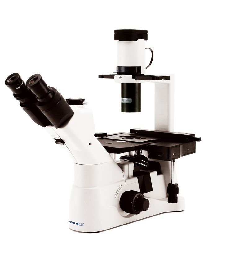
Warning
  This microscope is a scientific precision instrument designed to last for many years with a minimum of main-
  tenance. It is built to high optical and mechanical standards and to withstand daily use.
  We remind you that this manual contains important information on safety and maintenance, and that it must
  therefore be made accessible to the instrument users.
  We decline any responsibility deriving from incorrect instrument use that does not comply with this manual.

  Safety Information

         Avoiding Electrical Shock

  Before plugging in the power supply, make sure that the supplying voltage of your region matches with the
  operation voltage of the equipment and that the lamp switch is in off position.

  Users should observe all safety regulations of the region. The equipment has acquired the CE safety label.
  However, users do have full responsibility to use this equipment safely.
  Please follow the guidelines below, and read this manual in its entirety to ensure safe operation of the unit.

  Package Contents

   DESCRIPTION                                                              QUANTITY

   Microscope stand with head, stage, nosepiece, focus                      1
   WF 10X/22 eyepieces                                                      2
   IOS 10x objective                                                        1
   IOS 20x objective                                                        1
   IOS 40x objective                                                        1
   Illuminator                                                              1
   Sample holder (square)                                                   3
   Sample holder (round)                                                    2
   LBD and IF550 filter                                                     2
   Phase contrast slide                                                     1
   Mechanical stage                                                         1
   Dust cover                                                               1
   Power cable                                                              1

  Intended use
  For research and teaching and teaching use only. Not intended for any animal or human therapeutic or diag-
  nostic use.

  Symbols and conventions
  The following chart is an illustrated glossary of the symbols that are used in this manual.

                                  CAUTION
                                  This symbol indicates a potential risk and alerts you to proceed with
                                  caution

                                                              3

Heruntergeladen von manualslib.de Handbücher-Suchmachiene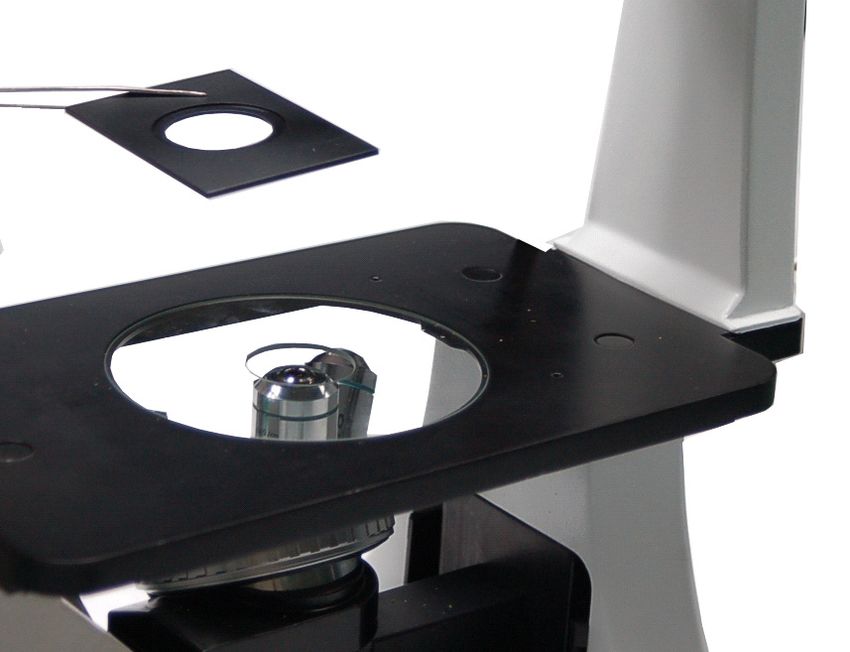
Unpacking
            The following figure shows the installation sequence of the components.
            he number in the figure shows the installation steps.

            •    Before installing, be sure every component is clean. Take care not to scratch parts or surfaces.
            •    Store the supplied hexagon wrench in a safe place. When changing the components, you will
                 need it again.

                                                                                      Microscope base

  Condenser                               2
  illumination
  unit

                                                      6
                                                                                                 Mechanical stage

        7                        1                                                    5

                                3
                                                                                4

                                                                            LED housing      Objectives
                 Glass stage        Stage extension
    Eyepiece
                                                            Filter holder

                                                             4

Heruntergeladen von manualslib.de Handbücher-Suchmachiene
Installation steps
  Installing the condenser illumination unit and the LED housing

  1.     Insert the condenser illumination unit (1) into the bracket, according to figure.
  2.     Turn the condenser illumination unit clockwise about 90°, with the “AS” mark of filter holder (3) facing
         forwards. Align the screw of the condenser illumination unit and the hole of the holder, then screw the
         bolt in the hole with the supplied hexagon spanner.
  3.     Insert the connector plug (2) into the connector jack (4).
  4.     Push the LED housing gently into the holes of the illumination unit.

                                             2               1

                                 3

                           1

  Installing the objectives
  1. Turning the coarse focusing knob (1) till the nosepiece reaches to its lowest position.
  ► For a safe transport, the nosepiece is placed in the lowest position and the tension adjustment
     collar (2) is adjusted to the appropriate tension when the microscope leaves the factory.

  2. Screw the lowest magnification objective on to the turret from the right side, then turn the turret clockwise.
     Mount the other objectives in the same way, following the sequence from low to high.
  ► Note: the objectives can also be installed through the stage opening.
  ► Clean the objectives regularly. In inverted microscopes, the objectives are very sensitive to dust.
  ► To prevent dust and contamination from entering the microscope, cover all the unused holes with dust
     caps (3).
  ► When operating, use the low magnification objective (10X) to search and focus the specimen, then switch
     to higher magnifications.
  ► When switching between objectives, slowly turn the nosepiece until it clicks. The click means that the
     objective is in the right position, in the center of the light path.

                                         1

                  2

                                                                             3

                                                              5

Heruntergeladen von manualslib.de Handbücher-Suchmachiene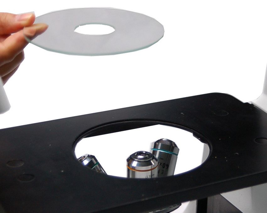
Installing the stage extension and the mechanical stage
           The stage extension can be installed on either side of the stage to enlarge the working surface. The mechani-
           cal stage must be installed on the side opposite the extension. The stage extension can be installed on either
           side of the stage to enlarge the working surface. The mechanical stage must be installed on the side opposite
           the extension.

           For right-handed operators, the mechanical stage is normally installed on the right side.

           1. Installing the stage extension: Screw the bolts (1) on to the extension, then mount the extension from
              below the stage. Screw it to a firm fit.

           2. Installing the mechanical stage: As for the extension, the mechanical stage is fixed by two bolts under the
              stage.
                                                      1

           Installing the stage insert

           1.     When using the glass stage (1), make sure that the stage is horizontal.

           2.     Install the stage insert in the stage opening.

                  Turn the disk until the V-groove faces the user. This simplifies objective identification.

                                                                           1

           Installing the eyepieces

           1.     Remove the cap of the eyepiece tubes (1).

           2.     Insert the eyepieces (2) into the tubes.

                                                                               1

                                                  2

                                                              6

Heruntergeladen von manualslib.de Handbücher-Suchmachiene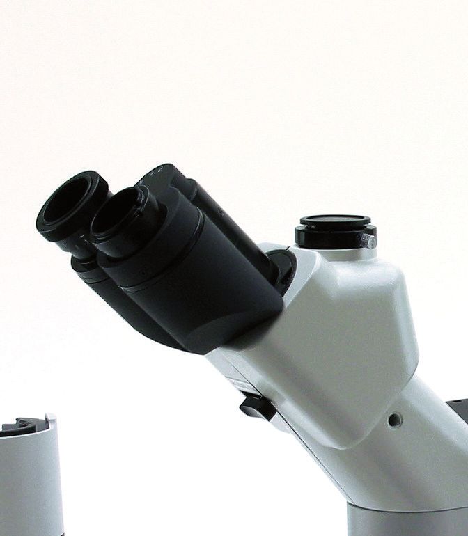
Installing the color filters

  ► Be sure the color filter has cooled down completely before you change them. Remove the filter
    holder (1), then install the color filters (2) you need.

       Mount the color filter flat as shown in (3), verifying that they are not tilted.

  ► If the color filter is tilted or otherwise out of place (4), it may fall.

       The color filters can be stacked in the holder. This allows to install as many filters as needed, as long as
       the whole thickness is less than 11 mm.

                                               2

                                                    2

                                               11

                                                    4                 3

  Connecting the power cord

  ► Do not tension or otherwise stress the power cord. If bent, the wires may easily break.

  1.   Turn the main switch (1) to “O”(off) before connecting the power cord.
  2.   Insert the plug into the power jack (2) of the microscope.
  3.   Plug the power cord (4) into the mains socket. Check for a safe connection.

  ► Please use the supplied power cord. If lost or damaged, please refer to qualified service.
  ► Connect the power cord to a grounded (earthed) power supply only.

  Replacing the fuse

  Before replacing the fuse, turn the main switch (1) to “O” (off) and unplug the power cord. Rotate the fuse
  support (3) out of the holder using a straight screwdriver. Insert a new fuse in the support, then rotate the
  support back into the holder.

  ► Fuse rating: see back of the microscope.

                                                                                     5
                                                                                                           4

                         1                              2                 3

                                                                  7

Heruntergeladen von manualslib.de Handbücher-Suchmachiene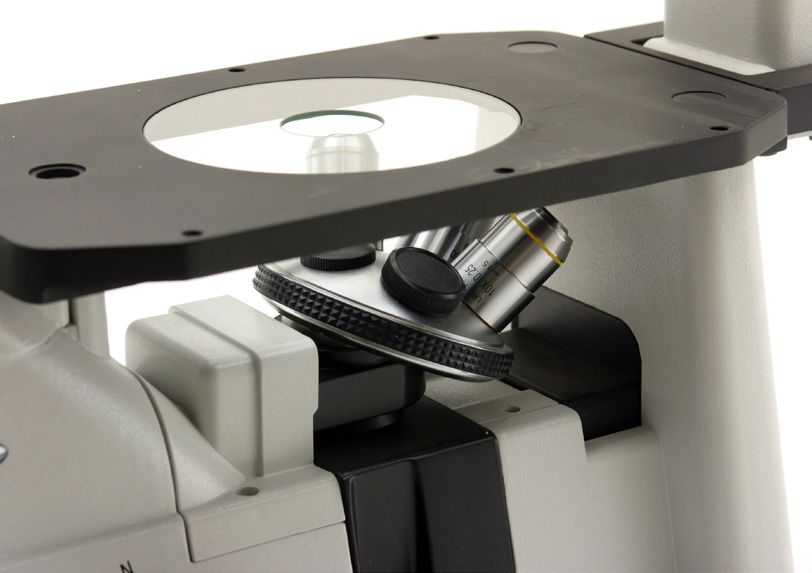
Product Specifications

   Illumination           Light source type P-LED8 with white 8W LED; light intensity control using a knob on left side of the frame.
                          Color temperature: 6300K
                          LED average life time approx. 50.000h
                          Voltage: 110/240Vac, 50/60Hz, 1A ; Fuse: T500mA 250V
                          Max power required: 13W
   Observation Modes      Brightfield, phase contrast
   Focusing               Coaxial coarse and fine focusing mechanism (graduated, 0.002mm) with upper stop, to prevent the contact
                          between objective and specimen.
                          Adjustable tension of coarse focusing knob.
   Stage                  Fixed stage, dimensions 250x230 mm.
                          Mechanical stage mountable on the right side of the stage, X-Y translation range 120x80 mm, with metallic
                          interchangeable inserts for slides, Petri dishes, Terasaki, multi-Well plates, etc.
                          Pair of side extensions to expand the surface of the stage.
                          Glass stage insert with hole for small dimension specimens.
   Nosepiece              Quintuple revolving nosepiece, rotation on ball bearings.
   Head                   Trinocular observation head, inclined 45°.
                          Diopter adjustment on left eyepiece.
                          Interpupillary adjustment 55-75 mm.
                          Splitting ratios (eyepieces-photo tube): 100-0 / 20-80
   Eyepieces              Wide field eyepieces WF10X/22 with field number 22.
   Objectives             Infinity corrected optical system IOS (Infinity Optical System).
                          Plan-achromatic LWD objectives infinity corrected, for thickness 1.2 mm, made by following objectives:
                          -) Plan-achromatic IOS LWD 10XPh, N.A. 0.25, W.D. 7.94 mm
                          -) Plan-achromatic IOS LWD 20XPh, N.A. 0.40, W.D. 7.66 mm
                          -) Plan-achromatic IOS LWD 40XPh, N.A. 0.60, W.D. 3.71 mm
                          All objectives are treated with an anti-fungus treatment.
   Condenser              LWD condenser, N.A. 0.30, working distance 72 mm.
                          The condenser can be removed to extend the working distance up to 150 mm.
                          Precentered slider with phase rings 4x/10x and 20x/40x.
   Dimensions             HEIGHT:           485 mm
                          WIDTH:            300 mm
                          DEPTH:            550 mm
                          WEIGHT:           9 kg
   Accessories            Hard case, instruction manual and dust cover included.

                                                                    8

Heruntergeladen von manualslib.de Handbücher-Suchmachiene
OVERVIEW

                                                                   LED HOUSING
          OBJECTIVES
                                   PHASE CONTRAST SLIDER
          - 10X (PH)
          - 20X (PH)
          - 40X

                                                                                 ILLUMINATION BRACKET

  EYEPIECES

                                                                                      CONDENSER

                                                                                             STAGE
           TRINOCULAR                                                                        INSERT
           VIEWING TUBE
           (FIXED

                                                                             OBJECTIVE TURRET
                                                                             (NOSEPIECE) (FIXED)
             MICROSCOPE BASE                       STAGE (FIXED)

                                                   - STAGE EXTENSION
                                                   - GLASS STAGE

                                                            9

Heruntergeladen von manualslib.de Handbücher-Suchmachiene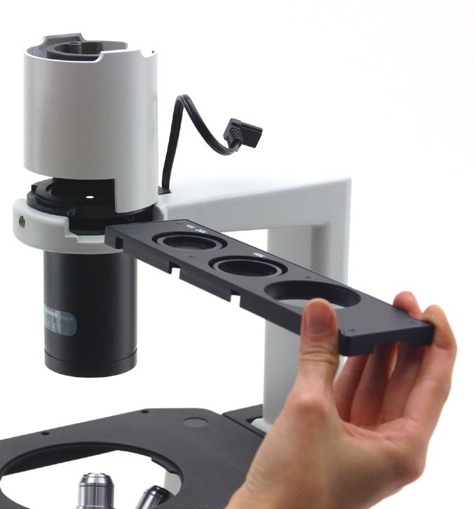
APERTURE DIAPHRAGM
                                              ADJUSTMENT LEVER
                                                                         COLOR FILTER HOLDER

                                  PHASE CENTERING
                                  BOLT

                                                                                    PHASE
                                                                                    CONTRAST SLIDER

   DIOPTRIC
   ADJUSTMENT RING

           LIGHT PATH
           SELECTOR LEVER

                                                                            FINE FOCUS KNOB
                TENSION                                     COARSE
                ADJUSTMENT                                  FOCUS KNOB
                COLLAR

                                                            10

Heruntergeladen von manualslib.de Handbücher-Suchmachiene
Operation
MICROSCOPE BASE
Turning on the LED
Connect the power, turn on the main switch (1).
Adjusting the brightness
Turn the brightness adjustment knob (2) to increase and decrease the brightness.
Adjusting the tension
► The coarse focusing knob (1) is pre adjusted to a tight tension upon leaving the factory.
If the nosepiece drops down by itself, or the specimen de focuses while adjusting the fine focus knob (3), the
coarse focus knob is too loose. Turning the tension adjustment collar (2) in the indicated direction tightens the
coarse focus tension (1). Rotate in the opposite direction to decrease the tension.
2 2 3 1
1
STAGE
Setting the specimen
► For the best image quality, use flasks, Petri dishes and slides with a 1.2 mm thickness.
Using Φ35mm culture dishes:
You can place a Φ 35 mm culture dish on the stage by using the standard center board (1) of the stage.
Using the mechanical stage:
1. When observing 96-well or 24-well micro-titration plates, please fasten them directly with the stage clip
(2).
2. When fastening other plates, please use the adaptor plates supplied with the mechanical stage:
● Terasaki bracket (3) for Terasaki boards
● Culture dish bracket (4) for Φ 35 mm culture dishes
● Object slide bracket (5) for object slides and Φ 54 mm culture dishes
3. Turning the X and Y knobs (6,7), move the specimen to the required position. (Movement Range: 120
(width) × 78 (length) mm).
1
2
6
7
3 5 4
11
Heruntergeladen von manualslib.de Handbücher-SuchmachieneMoving the specimen
Move the specimen to the desired position by freehand or by turning the knobs of the mechanical stage.
► When switching objectives, take care not to touch the adaptor plates with the objectives, as their
weight may damage the front lens.
VIEWING TUBE
Dioptric adjustment
1.Look into the right eyepiece with your right eye only, and focus on the specimen.
2.Look into the left eyepiece with your left eye only. If the image is not sharp, use the dioptric adjustment
ring (1) to compensate.
► The adjustment range is ±5 diopter. The number indicated on the adjustment ring graduation
should correspond to the operator’s dioptric correction.
Adjusting the interpupillary distance
Observing with both eyes, hold the two eyepiece prism assemblies. Rotate them around their common axis
until the fields of view coincide.
► The graduation on the interpupillary distance indicator (3), pointed by the spot “.” (2) on the eye-
piece holder, shows the distance between the operator’s eyes.
The range of the interpupillary distance is 48-75mm.
Selecting the light path
Pull the light path selector lever (1) sideways using your thumb, selecting the light path you need.
1
LIGHT PATH SELECTOR BRIGHTNESS APPLICATION
LEVER
In 100% used for binocular Binocular observation
observation
Out 20% used for binocular observa- Binocular observation, television,
tion, and 80% used for video or and micrography or video can be
photography operated simultaneously
ILLUMINATION UNIT
Using color filters
Selecting the appropriate color filters according your need.
You can stack a group of color filters in the filter holder, if you ensure that they are level and that the whole
thickness is less than 11mm.
12
Heruntergeladen von manualslib.de Handbücher-SuchmachieneCOLOR FILTER USE
In Single contrast color filter (green) used for phase contrast microscopy
Out Color temperature compensation color filter blue used for bright field obser-
vation and microphotography
1 70-80%
70-
80%
30-20%
30-
20%
2
Using the aperture diaphragm
When in bright field observation, the aperture diaphragm controls the numerical aperture of the illumination
system. When the numerical aperture of the objective and the aperture of the illumination system match, the
highest resolution is achieved.
To identify the aperture diaphragm, the eyepiece can be removed or the centering telescope can be used.
The aperture can be changed by moving the aperture adjustment lever. ((1)is the image of the aperture dia-
phragm, (2) is the edge of the objective).
Generally, when observing a fully chromatic specimen, you need to set the size of the condenser to 70-80%
of the aperture of the objective. When observing unstained samples (e.g. bacteria), start from 70% and slowly
turn the aperture diaphragm lever clockwise.
IDENTIFYING THE COMPONENTS
Phase contrast objectives
The magnifications of the optional phase contrast objectives are: 10X and 20X. These objectives are marked
“PH”. Mount the objectives on the turret using the same procedures as the standard objectives
1
2
Phase contrast slider
3
Adjustable phase slider.
● The light ring is pre-centered when the microscope leaves the
factory. It should therefore need no further adjustment. If a re-
centering is needed, it can be performed via the two side bolts.
● The 4X/10X light ring (1) must be used with 4X and 10X phase
contrast objectives, the 20x/40x light ring (2) with the 20x and
40x and the opening (3) is used for bright field.
13
Heruntergeladen von manualslib.de Handbücher-SuchmachieneSETUP AND USE
Installing the phase contrast slider
1. Insert the slider into the illumination system, printed face up.
2. Pull the slider into the desired position, to the click stop.
3. When in phase contrast observation, keep the aperture diaphragm adjustment lever on the “O” (open)
position.
Centering the ring
► Usually this operation is not needed. If necessary, please proceed with the following steps:
1. Place a specimen on the stage and focus it.
2. Take out the eyepiece from the tube without the dioptric adjustment, and replace it with the centering
telescope (CT).
3. Check that the phase ring and the objective correspond, and that both are steadily set on a click stop.
4. Use the CT to focus on the light ring’s image (5) and the phase contrast ring’s image (2). If the light ring’s
image is not sharp, adjust the CT’s eyepiece until you can see a clear image of the light ring (2).
5. Adjust the bolts of the two centering holes in the phase contrast slider using a screwdriver until the light
ring center and the phase contrast ring center coincide.
6. The 10X and the 20X phase contrast objectives use the same ring on the phase contrast slider. The co-
incidence of the light ring center and the phase contrast center must be verified with both objectives.
► If the light ring is centered incorrectly, the contrast will be severely impaired.
► The phase ring may need recentering during and after observation of very thick specimens.
► The phase ring may show an apparent misalignment if the cover glass is not flat.
1
2
14
Heruntergeladen von manualslib.de Handbücher-SuchmachieneVIDEO PORT (VIDEO)
Selecting the light path
1. To activate the video port, pull out the light path selector lever.
► For observation of dark specimens, first focus, then pull out the lever.
Installing the video adapter
► Usually this operation is not needed. If necessary, please proceed with the following steps:
1. Loosen the locking bolt (1) on the trinocular viewing tube, and take out the dust cap (2).
2. Set up the video adapter on the camera according to its instructions.
3. Install the adapter into the tri-through port, and screw down the bolt (1).
Focus
During a binocular observation at 20% brightness, look at the image on the video imaging system, refo-
cusing the adapter if necessary.
MICROPHOTOGRAPHY
Installing the photography adapter
1. Loosen the locking bolt (1) on the trinocular viewing tube, and take out the dust cap (2).
2. Install the photography adapter into the tri-through port according to its instructions, and screw down the
locking bolt (1).
3. Attach the camera ring (if any) to the adapter.
4. Attach the camera to the ring.
● Warning: for some cameras (mainly reflex) the ring is not included with the microscope, and it should be
supplied by the user.
● For the photography of dark specimens, obscure the eyepieces and the viewfinder with a dark cloth in
order to reduce stray light.
● The camera magnification can be calculated as objective magnification × camera + lens magnifica-
tion.
► When shooting with a SLR, the mirror movement may cause camera movement. Please lift the
mirror, use long exposure times and use an extension cord.
Video Camera
CCD Camera head
Adapter Adapter
2 2
1 1
1
15
Heruntergeladen von manualslib.de Handbücher-SuchmachieneTroubleshooting
Review the information in the table below to troubleshoot operating problems.
PROBLEM CAUSE SOLUTION
I. Optical Section:
1. The illumination is open, but The plug of the LED holder Connect them
the field of view is dark. is not connected to the il-
lumination set
The brightness is too low Adjust to a proper setting
Too many colour filters have Minimize the number of the filters
been stacked
2. The edge of the field of view The nosepiece is not in the Turn the nosepiece to a click stop
is vignetted or the brightness is correct position
asymmetric. The color filter is partially Insert the filter to full depth
inserted
The phase contrast slider is Move the slider to a click stop
not in the proper position
3. Dust and stains can be seen in There are stains and dust on Clean the specimen
the field of view. the specimen
There are stains and dust on Clean the eyepiece
the eyepiece
4. There is an apparent double The size of the aperture Open the aperture diaphragm
image. diaphragm is too small
5. Poor image quality: The nosepiece is not in the Turn the nosepiece to a click stop
The image is not sharp center of the light path
The contrast is not high The aperture diaphragm in Adjust the aperture diaphragm
The details are not clear the view of field is opened
The phase contrast is low. too much or too little
The lenses (condenser, Thoroughly clean all the optical system
objective, eyepieces are
culture dish) is dirty
In phase contrast observa- Use a sample holder whose bottom
tion, the bottom thickness thickness is less than 1.2mm
of the sample is more than
1.2mm
A bright field objective is Switch to a phase contrast objective
used for phase contrast
observation
The condenser ring is not Adjust the condenser ring to match the
aligned with the objective objective phase ring
phase ring
The light ring and/or the Adjust the bolts to center them
phase contrast ring is not
centered
The objective used is not Please use a compatible objective
compatible with the phase
ring
The phase contrast depends The sample holder is not flat. Move the
on the sample position sample around until a compatible area
is found.
16
Heruntergeladen von manualslib.de Handbücher-Suchmachiene6. One side of the image is out of The nosepiece is not in the Turn the nosepiece to a click stop
focus. center of the light path
The specimen is out of place Place the specimen flat on the stage.
(tilted)
The optical performance of Use a cover glass of better quality
the sample cover glass is
poor
II. Mechanical Section:
1.The coarse focus knob is hard The tension adjustment col- Loosen the tension adjustment collar
to turn. lar is too tight
2.The focus is unstable. The tension adjustment col- Tighten the tension adjustment collar
lar is too loose
III. Electric section
1. The LED doesn’t turn on. No power supply Check the power cord connection
2. The brightness is not enough The brightness adjustment Adjust the brightness
is low
3. The light blinks The power cord is poorly Check the power cord
connected
IV. Viewing tube assembly
3. The field of view of the two The interpupillar distance is Adjust the interpupillar distance
eyes is different not correct
The dioptric correction is not Adjust the dioptric correction
right
The viewing technique is not When look into the objective, do not
correct, and the operator is stare at the specimen but look at the
straining the eyesight whole field of view. Periodically, move
the eyes away to look at a distant ob-
ject, then back into the objective
V. Microphotography and video
1. The image is unfocused Incorrect focussing Adjusting the focus system as in the
present manual
2. The edge of the image is To some degree, it is inher- The problem can be minimized by a
unfocussed ent to the nature of achro- correct setting of the aperture dia-
matic objectives phragm
3. Bright patches appear on the Stray light is entering the Cover the eyepieces and the viewfind-
image microscope through the er with a dark cloth
eyepieces and through the
camera viewfinder
17
Heruntergeladen von manualslib.de Handbücher-SuchmachieneRepair and maintenance
Microscopy environment
This microscope is recommended for use in a clean, dry and shock free environment with a temperature of
0-40°C and a maximum relative humidity of 85 % (non condensing). Use a dehumidifier if needed.
To think about when and after using the microscope
The microscope should always be kept vertical when moving it so that no moving parts, such as the eye-
pieces, fall out. Never mishandle or impose unnecessary force on the microscope.
Never attempt to service the microscope yourself.
After use, turn down the illumination intensity control and turn the light off. Cover the microscope with included
the dust cover, and keep it in a dry and clean place.
Electrical safety precautions
Before plugging in the power supply, make sure that the supplying voltage of your region matches with the
operation voltage of the equipment and that the lamp switch is in off-position.
Users should observe all safety regulations of the region. The equipment has acquired the CE safety label.
However, users do have full responsibility to use this equipment safely.
Cleaning the optics
If the optical parts require cleaning first use compressed air.
If that is not sufficient use a soft lint-free cloth with water and a mild detergent.
And as a final option use the piece of cloth moistened with a 3:7 mixture of ethanol and ether.
Note: ethanol and ether are highly flammable liquids. Do not use them near a heat source, near sparks or
near electric equipment. Use these chemicals in a well ventilated room.
Remember to never wipe the surface of any optical items with your hands. Fingerprints can damage the op-
tics. Do not disassemble objectives or eyepieces in an attempt to clean them.
For the best results, use the VWR cleaning kit (see catalog number below).
If you need to send the microscope to manufacturer for maintenance, please use the original packag-
ing.
18
Heruntergeladen von manualslib.de Handbücher-SuchmachieneUser replaceable accessories and spare parts
DESCRIPTION QUANTITY CAT. NO.
Eyepiece EWF10X/22MM 2 630-2163
WF10x/22mm micrometer eyepiece (10mm, 0.1mm div.) 1 630-1968
Slide micrometric 26x76mm 1mm 1 630-1650
Objective IOS LWD PLAN achromatic 4x/0,10 (w.d. 22mm) 1 630-2164
Objective IOS LWD PLAN achromatic for phase contrast 10x/0,25 1 630-2165
(w.d. 7,94mm)
Objective IOS LWD PLAN achromatic for phase contrast 20x/0,40 1 630-2166
(w.d. 7,66mm)
Objective IOS LWD PLAN achromatic for phase contrast 40x/0,60 1 630-2167
(w.d.3,71mm)
Objective IOS LWD PLAN achromatic 60x/0,70 (w.d. 2,50mm) 1 630-2168
Cut-off filter (infrared) 1 630-2169
Photo adapter for REFLEX camera with FULL FRAME sensor 1 630-2170
1/3” CCD camera adapter 1 630-1891
1/2” CCD camera adapter 1 630-1892
Universal adapter for cameras (only models with eyepiece adapter, 1 630-2172
23mm)
Dust cover type 7 1 630-1769
Phototube adapter for APS-C sensor 1 630-1645
Set for cleaning and maintenance of microscopes 1 630-2081
Immersion oil 8ml 1 630-1808
19
Heruntergeladen von manualslib.de Handbücher-SuchmachieneTechnical service
Web Resources
Visit the VWR’s website at www.vwr.com for:
• Complete technical service contact information
• Access to VWR’s Online Catalogue, and information about accessories and related products
• Additional product information and special offers
Contact us For information or technical assistance contact your local VWR representative or visit. www.
vwr.com.
Warranty
VWR International warrants that this product will be free from defects in material and workmanship for a
period of five (5) years from date of delivery. If a defect is present, VWR will, at its option and cost, repair,
replace, or refund the purchase price of this product to the customer, provided it is returned during the war-
ranty period. This warranty does not apply if the product has been damaged by accident, abuse, misuse, or
misapplication, or from ordinary wear and tear. If the required maintenance and inspection services are not
performed according to the manuals and any local regulations, such warranty turns invalid, except to the ex-
tent, the defect of the product is not due to such non-performance.
Items being returned must be insured by the customer against possible damage or loss. This warranty shall
be limited to the aforementioned remedies. IT IS EXPRESSLY AGREED THAT THIS WARRANTY WILL BE
IN LIEU OF ALL WARRANTIES OF FITNESS AND IN LIEU OF THE WARRANTY OF MERCHANTABILITY.
Compliance with local laws and regulations
The customer is responsible for applying for and obtaining the necessary regulatory approvals or other au-
thorizations necessary to run or use the Product in its local environment. VWR will not be held liable for any
related omission or for not obtaining the required approval or authorization, unless any refusal is due to a
defect of the product.
Disposal
This equipment is marked with the crossed out wheeled bin symbol to indicate that this equipment must not
be disposed of with unsorted waste.
Instead it is your responsibility to correctly dispose of your equipment the end of its life cycle by handling it
over to an authorized facility for separate collection and recycling. It is also your responsibility to decontami-
nate the equipment in case of biological, chemical and/or radiological contamination, so as to protect from
health hazards the persons involved in the disposal and recycling of the equipment.
For more information about where you can drop off your waste equipment, please contact your local dealer
from whom you originally purchased this equipment.
By doing so, you will help to conserve natural and environmental resources and you will ensure that your
equipment is recycled in a manner that protects human health.
Thank you
20
Heruntergeladen von manualslib.de Handbücher-Suchmachiene21 Heruntergeladen von manualslib.de Handbücher-Suchmachiene
Australia                               Hungary                                    Singapore
       VWR International, Pty Ltd.             VWR International Kft.                     VWR Singapore Pte Ltd
       Unit 1/31 Archimedes Place              Simon László u. 4.                         18 Gul Drive
       Murarrie, Queensland 4172               4034 Debrecen                              Singapore 629468
       Tel.: 1300 727 696                      Tel.: (52) 521-130                         Tel.: +65 6505 0760
       Fax: 1300 135 123                       Fax: (52) 470-069                          Fax: +65 6264 3780
                                               E-mail: info@hu.vwr.com                    E-mail: sales@sg.vwr.com
       Austria
       VWR International GmbH                  India
       Graumanngasse 7                         VWR Lab Products Private Limited           Spain
       1150 Vienna                             135/12, Brigade Towers, 2nd Floor          VWR International Eurolab S.L.
       Tel.: +43 1 97 002 0                    Front wing, Brigade Road,                  C/ Tecnología 5-17
       Fax: +43 1 97 002 600                   Bengaluru, India – 560 025                 A-7 Llinars Park
       E-mail: info@at.vwr.com                 Tel.: +91-80-41117125/26 (Bengaluru)       08450 - Llinars del Vallès
                                               Tel.: +91-2522-647911/922 (Mumbai)         Barcelona
       Belgium                                 Fax: +91-80-41117120                       Tel.: 902 222 897
       VWR International bvba                  E-mail: vwr_india@vwr.com                  Fax: 902 430 657
       Researchpark Haasrode 2020                                                         E-mail: info@es.vwr.com
       Geldenaaksebaan 464                     Ireland / Northern Ireland
       3001 Leuven                             VWR International Ltd /                    Sweden
       Tel.: 016 385 011                       VWR International (Northern Ireland) Ltd   VWR International AB
       Fax: 016 385 385                        Orion Business Campus                      Fagerstagatan 18a
       E-mail: customerservice@be.vwr.com      Northwest Business Park                    163 94 Stockholm
                                               Ballycoolin                                Tel.: 08 621 34 00
       China                                   Dublin 15                                  Fax: 08 621 34 66
       VWR International China Co., Ltd        Tel.: 01 88 22 222                         E-mail: kundservice@se.vwr.com
       Rm.219, 2100 Dongming Road              Fax: 01 88 22 333
       Pudong New District                     E-mail: sales@ie.vwr.com                   Switzerland
       Shanghai 200123                                                                    VWR International GmbH
       Tel.: +86-21-5898 6888                  Italy                                      Lerzenstrasse 16/18
       Fax: +86-21-5855 8801                   VWR International PBI S.r.l.               8953 Dietikon
       E-mail: info_china@vwr.com              Via San Giusto 85                          Tel.: 044 745 13 13
                                               20153 Milano (MI)                          Fax: 044 745 13 10
       Czech Republic                          Tel.: 02-3320311/02-487791                 E-mail: info@ch.vwr.com
       VWR International s. r. o.              Fax: 800 152999/02-40090010
       Veetee Business Park                    E-mail: info@it.vwr.com                    Turkey
       Pražská 442                                                                        Pro Lab Laboratuar Teknolojileri Ltd.Şti.
       CZ - 281 67 Stříbrná Skalice            The Netherlands                            a VWR International Company
       Tel.: +420 321 570 321                  VWR International B.V.                     Orta Mah. Cemal Gürsel Caddesi
       Fax: +420 321 570 320                   Postbus 8198                               Ördekcioglu Işmerkezi No.32/1
       E-mail: info@cz.vwr.com                 1005 AD Amsterdam                          34896 Pendik - Istanbul
                                               Tel.: 020 4808 400                         Tel.: +90216 598 2900
       Denmark                                 Fax: 020 4808 480                          Fax: +90216 598 2907
       VWR - Bie & Berntsen                    E-mail: info@nl.vwr.com                    Email: info@pro-lab.com.tr
       Transformervej 8
       2730 Herlev                             New Zealand                                UK
       Tel.: 43 86 87 88                       Global Science - A VWR Company             VWR International Ltd
       Fax: 43 86 87 90                        241 Bush Road                              Customer Service Centre
       E-mail: info@dk.vwr.com                 Albany 0632, Auckland                      Hunter Boulevard - Magna Park
                                               Tel.: 0800 734 100                         Lutterworth
       Finland                                 Fax: 0800 999 002                          Leicestershire
       VWR International Oy                    E-mail: sales@globalscience.co.nz          LE17 4XN
       Valimotie 9                                                                        Tel.: 0800 22 33 44
       00380 Helsinki                          Norway                                     Fax: 01455 55 85 86
       Tel.: 09 80 45 51                       VWR International AS                       E-mail: uksales@uk.vwr.com
       Fax: 09 80 45 52 00                     Haavard Martinsens vei 30
       E-mail: info@fi.vwr.com                  0978 Oslo
                                               Tel.: 02290
       France                                  Fax: 815 00 940
       VWR International S.A.S.                E-mail: info@no.vwr.com
       Le Périgares – Bâtiment B                                                          GO TO VWR.COM FOR THE
       201, rue Carnot                         Poland                                     LATEST NEWS, SPECIAL OFFERS
       94126 Fontenay-sous-Bois cedex          VWR International Sp. z o.o.
       Tel.: 0 825 02 30 30 (0,15 € TTC/min)   Limbowa 5                                  AND DETAILS OF YOUR LOCAL
       Fax: 0 825 02 30 35 (0,15 € TTC/min)    80-175 Gdansk                              VWR DISTRIBUTOR
       E-mail: info@fr.vwr.com                 Tel.: 058 32 38 200 do 204
                                               Fax. 058 32 38 205
       Germany                                 E-mail: info@pl.vwr.com
       VWR International GmbH
       Hilpertstraße 20a                       Portugal
       D - 64295 Darmstadt                     VWR International -
       Freecall: 0800 702 00 07                Material de Laboratório, Lda
       Fax: 0180 570 22 22*                    Edifício Neopark
       Email: info@de.vwr.com                  Av. Tomás Ribeiro, 43- 3 D
       *0,14 €/Min. aus d. dt. Festnetz        2790-221 Carnaxide
                                               Tel.: 21 3600 770
                                               Fax: 21 3600 798/9
                                               E-mail: info@pt.vwr.com

                                                                  22

Heruntergeladen von manualslib.de Handbücher-Suchmachiene
VWR
Microscope series 400
MANUEL D’UTILISATION
Modèle European Catalogue Number
IT405 630-2080
Version: 6
du: 20, 10, 2014
Heruntergeladen von manualslib.de Handbücher-SuchmachieneAdresse du Fabricant
Europe
VWR International bvba
Researchpark Haasrode 2020
Geldenaaksebaan 464
B-3001 Leuven
+ 32 16 385011
http://be.vwr.com
Pays d’origine: ITALIE
Contenu
Avertissement
Précautions
Contenu de l’emballage
Usage
Symboles et conventions
Déballage
Etapes de montage
Spécifications du produit
Vue d’ensemble
Opération
Résolution des problèmes
Réparation et entretien
Accessoires de substitution de l’utilisateur et pièces de rechange
Service technique
Garantie
Conformité à la législation et aux réglementations locales
Ramassage
24
Heruntergeladen von manualslib.de Handbücher-SuchmachieneAvertissement
Le présent microscope est un appareil scientifique de précision créé pour offrir une durrée de vie de plusieurs
années avec un niveau d’entretien mininum. Les meilleurs composants optiques et mécaniques ont été utili-
sés pour sa conception ce qui fond de lui un appareil idéal pour une utilisation journalière.
Ce guide contient des informations importantes sur la sécurité et l’entretien du produit et par conséquent il
doit être accessible à tous ceux qui utilisent cet insrument.Nous déclinons toute responsabilité quant à des
utilisations de l’instrument non conformes au présent manuel.
Précautions
Précautions de sécurité sur le système électrique
Avant de connecter le câble d’alimentation au réseau électrique assurez vous que la tension d’entrée soit
compatible avec celle de l’appareil et que l’interrupteur de l’éclairage soit en position arrêt.
L’utilisateur devra consulter les normes de sécurités de son pays. L’appareil inclu une étiquette de sécurité
C.E. Dans tous les cas, l’utilisateur assume toute responsabilité relative à l’utilisation sûre de l’appareil.
Suivre les directives ci-dessous et lire ce manuel dans son intégralité pour un fonctionnement sûr de l’instru-
ment.
Contenu de l’emballage
DESCRIPTION QUANTITÉ
Statif du microscope avec tête, platine, revolver et mise au point 1
Oculaires WF 10/22 2
Objectif IOS 10x 1
Objectif IOS 20x 1
Objectif IOS 40x 1
Éclairage 1
Porte-échantillon (carré) 3
Porte-échantillon (rond) 2
Filtres LBD et IF550 2
Lame pour contraste de phase 1
Platine avec surplatine 1
Housse de protection 1
Câble d’alimentation 1
Usage
Uniquement pour la recherche. Non destiné à usage thérapeutique ou diagnostique sur animaux ou êtres
humains.
Symboles et conventions
Le tableau suivant est un glossaire illustré des symboles qui sont utilisés dans ce manuel.
ATTENTION
Ce symbole indique un risque potentiel et vous avertit de procéder
avec prudence
25
Heruntergeladen von manualslib.de Handbücher-SuchmachieneDéballage
La figure suivante montre l’ordre d’installation des composantes. Le nombre dans la figure montre les diffé-
rents étapes de l’installation.
• Avant le montage, soyez sûrs que toutes les composantes sont propres. Faites attention de ne
pas endommager ou rayer des parties ou des surfaces.
• Conservez la clé fournie dans un endroit sûr. En changeant les composantes, vous en aurez
besoin de nouveau.
Base microscope
Unité 2
illumination
condenseur
6
Platine mécanique
7 1 5
3
4
Logement LED Objectifs
Platine en verre Extension platine
Oculaires
Porte-filtres
26
Heruntergeladen von manualslib.de Handbücher-SuchmachieneEtapes de montage
Installation de l’unité d’illumination du condenseur et du LED
1. Insérer l’unité d’illumination du condenseur (1) dans le support (selon la figure 4).
2. Tourner l’unité d’illumination du condensateur dans le sens des aiguilles d’une montre à environ 90 °,
la marque “ AS” du porte-filtres faisant face (3) continuer, en alignant la vis de l’unité d’illumination du
condenseur et le trou du support, visser ensuite le verrou dans le trou avec la clé de serrage fournie.
3. Insérer la prise de courant de connexion (2) dans le cric de connexion (4).
4. Placer le logement LED doucement dans l’unité d’illumination.
2 1
3
1
Installation des objectifs
1. Tournant le bouton de la mise au point (1) jusqu’à la plus basse position du revolver.
► Pour un transport sûr, le revolver est placé dans la position la plus basse et le bouton de com-
mande de la tension (2) est réglé à la tension appropriée à la sortie d’usine du microscope.
2. Visser l’objectif de grossissement le plus faible sur la tourelle du côté juste, dans le sens des aiguilles
d’une montre. Monter les autres objectifs de la même façon, selon l’ordre du plus faible au plus fort agran-
dissement.
► Note: les objectifs peuvent aussi être installés à travers l’ouverture de la platine.
► Nettoyer régulièrement les objectifs. Dans les microscopes inversés, les objectifs sont très sensibles à la
poussière.
► Recouvrir tous les trous inutilisés à l’aide des bouchons pour une protection contre la poussière et la
contamination (3).
► Pour la mise en fonctionnement, utiliser l’objectif de grossissement faible (10X, chercher à focaliser
l’échantillon, passer ensuite aux grossissements plus forts.
► En changeant l’objectif, tourner lentement le revolver jusqu’à ce qu’il fasse un déclic. Ce qui signifie que
l’objectif est dans la position juste, au centre du parcours de la lumière.
1
2
3
27
Heruntergeladen von manualslib.de Handbücher-SuchmachieneInstallation de l’extension de la platine et de la platine mécanique
L’extension de platine peut être installée de chaque côté de la platine pour élargir la surface de travail. La
platine mécanique doit être installée sur le côté opposé de l’extension.
Pour les opérateurs droitiers, la platine mécanique est installée normalement sur le côté droit.
1. Installation de l’extension de la platine d’abord, visser les verrous (1) sur l’extension, monter ensuite
l’extension en dessous de la platine. Verrouiller avec la vis appropriée.
2. Installation de la platine mécanique: comme pour l’extension, la platine mécanique est fixée par deux vis
sous de la platine.
1
Installation de la platine d’insertion
1. En utilisant la plate-forme en verre (1), s’assurer qu’elle est horizontale.
2. Installer la plate-forme dans l’ouverture de la platine.
Tourner le disque jusqu’à ce que le sillon-V fasse face à l’utilisateur.
Cela simplifie l’identification des objectifs.
1
Installation des oculaires
1. Enlever le bouchon des tubes oculaire (1).
2. Insérer les oculaires (2) dans les tubes.
1
2
28
Heruntergeladen von manualslib.de Handbücher-SuchmachieneInstallation des filtres en couleur
► S’assurer que le filtre en couleur soit complètement refroidi avant de les changer. Enlever le
porte-filtres (1), ensuite installer les filtres en couleur (2) que vous désirez.
Monter les supports plats du filtre en couleur comme illustré dans (3), en vérifiant qu’ils ne sont pas inclinés
► Si le filtre en couleur est incliné ou placé autrement, les filtres de couleur peuvent tomber (4).
Les filtres de couleur peuvent être empilés dans le support. Cela permet d’installer autant de filtres dési-
rés, dans la mesure où l’épaisseur entière est inférieure à 11 millimètres.
2
2
11
4 3
Branchement du câble d’alimentation
► Pas de pression ou autre effort sur le câble d’alimentation. Lorsqu’il est tordu, les fils peuvent se
casser facilement.
1. Placer l’interrupteur principal (1) sur “O” avant de brancher le câble d’alimentions.
2. Insérer la prise de courant (2) sur le cric d’alimentation du microscope.
3. Brancher le câble d’alimentation sur la douille d’alimentation principale. Vérifier pour une connexion sûre.
► Utiliser s’il vous plaît le câble d’alimentation fourni. S’adresser au service compétent lorsqu’il est
endommagé ou perdu.
► Brancher le câble d’alimentation à une source d’alimentation électrique (à terre) seulement.
Remplacement du fusible
Placer l’interrupteur principal (1) sur “O” avant de remplacer le fusible et débrancher le câble d’alimentation.
Faire tourner le support du fusible (3) utilisant un tournevis droit. Insérer un nouveau fusible dans le support,
replacer le support à l’intérieur du dispositif.
► Voir la partie postérieure du microscope pour les valeurs du fusible.
5
4
1 2 3
29
Heruntergeladen von manualslib.de Handbücher-SuchmachieneSpécifications du produit
Éclairage P-LED8 avec LED blanche 8W.
Réglage de la luminosité par un rhéostat situé sur le côté gauche de la base du statif.
Température de 6300K.
Durée de vie moyenne de la LED 50.000 heures.
Tension: 110/240VAC, 50/60Hz, 1A Fusible: 250V T500
Observation Fond clair, contraste de phase.
Mise au point Système de mise au point macrométrique et micrométrique coaxiale (graduée, 0.002mm) avec système d’arrêt
pour empêcher le contact entre l’objectif et la préparation.
La tension de la commande macrométrique est réglable.
Platine Platine fixe, dimensions 250x230 mm.
Surplatine mécanique applicable sur le côté droit du statif, rang 120x80 mm, avec insert métalliques interchan-
geables pour les lames, pour les boîtes Pétri, les Terasaki, les plaques multi-Well, etc.
Paire d’extensions latérales pour augmenter la surface d’appui de la platine. Disque perforé en verre pour
accueillir de petits échantillons.
Revolver Revolver quintuple,avec rotation sur roulements à billes.
Tête Tête d’observation trinoculaire, inclinée à 45 °.
Réglage dioptrique oculaire gauche.
Réglage de la distance interpupillaire 55-75 mm.
Répartition de la lumière oculaires-port trino: 100-0 / 20-80
Oculaires Oculaires grand champ WF10X/22 avec index de champ 22.
Objectifs Système optique corrigé à l’infini - IOS (Infinity Optical System).
Système optique plan-achromatique LWD corrigé à l’infini, composé des objectifs suivants:
-) Plan Achromatique IOS LWD 10XPh, O.N. 0.25, W.D. 7,94 mm
-) Plan Achromatique IOS LWD 20XPh, O.N. 0.40, W.D. 7,66 mm
-) Plan Achromatique IOS LWD 40XPh, O.N. 0.60, W.D. 3,71 mm
Tous les objectifs sont traités avec système anti-fongique.
Condenseur Condenseur LWD, O.N. 0,30, distance de travail 72 mm.
Le condenseur peut être retiré pour augmenter la distance de travail jusqu’à 150 mm.
Coulisseau avec anneaux de phase 4X/10X et 20x/40X precentré.
Dimensions HAUTEUR: 485 mm
LARGEUR: 300 mm
PROFONDEUR: 550 mm
POIDS: 9 kg
Accessoires Mallette en métal, manuel d’instructions et housse de protection anti-poussière inclus.
30
Heruntergeladen von manualslib.de Handbücher-SuchmachieneVUE D’ENSEMBLE
OBJECTIFS LOGEMENT LED
DISPOSITIF CONTRASTE
- 10X (PH)
PHASE
- 20X (PH)
- 40X
SUPPORT ILLUMINATION
OCULAIRES
CONDENSEUR
TUBE D’OBSERVATION INSERTION
TRINOCULAIRE (FIXE) PLATE-FORME
TOURELLE PORTE-OB-
JECTIFS (REVOLER)
MICROSCOPE BASE (FIXE)
PLATINE (FIXE)
- EXTENSION PLATINE
- PLATINE EN VERRE
31
Heruntergeladen von manualslib.de Handbücher-SuchmachieneLEVIER RÉGLAGE
DIAPHRAGME D’OUVER-
TURE
PORTE-FILTRE COULEUR
BUTÉE DE CENTRAGE
DISPOSITIF
CONTR. PHASE
ANNEAU
D’AJUSTEMENT
LEVIER DE SÉLEC-
TION
MISE AU
RÉGLAGE TENSION POINT FINE
MISE AU POINT
32
Heruntergeladen von manualslib.de Handbücher-SuchmachieneOpération
RÉGLAGE DU MICROSCOPE
Mise en marche de la lampe
Brancher le câble, mettre en fonctionnement l’intérrupteur principal (1).
Réglage éclairage
Tourner le bouton de commande de l’éclairage (2) pour augmenter et abaisser l’éclairage.
Réglage de la Tension
► Le bouton de réglage (1) est déjà placé à une tension adaptée à la sortie d’usine.
Si le revolver descend tout seul, ou l’échantillon n’est plus focalisé au moment de régler la mise au point
fine (3), alors le bouton de mise au point macroscopique est trop desserré. Tourner le col du bouton de com-
mande de la tension (2) dans la direction indiquée, serrer la commande macrométrique (1). Tourner dans la
direction opposée pour diminuer la tension.
1 2 2 3 1
PLATINE
Mise en place des échantillons
► Pour la meilleure qualité d’image, utiliser des bouteilles, des capsules de Petri et des lames d’une
épaisseur de 1.2 millimètres.
Utiliser des plates-formes de culture de Φ 35mm:
Vous pouvez placer le plates-formes de culture deΦ35mm sur la platine en utilisant les bords standards du
centre (1) de la platine. Utilisation de la platine mécanique:
1. Durant l’observation des coffrets -96 ou -24 des plaques de micro-titration, il faut utiliser les pincettes de
la platine pour les fixer directement (2).
2. Pour placer d’autres plaques, utiliser s’il vous plaît les plaques d’adaptation fournies avec la platine
mécanique:
● Support Terasaki (3) pour les axes Terasaki
● Support de plaque de culture (4) pour les plaques de culture de Φ35mm.
● Pincette porte-objets (5) pour fixer les lames et les plaques de culture de Φ54mm
3. Utilisant les commandes X et Y (6,7), placer l’échantillon à la position désirée. (Axes de Mouvement: 120
(la largeur) × 78 (la Longueur) mm).
1
2
6
7
3 5 4
33
Heruntergeladen von manualslib.de Handbücher-SuchmachieneDéplacement de l’échantillon
Placer l’échantillon dans la position désirée utilisant les mains ou les boutons de commande de la platine
mécanique.
► En changeant les objectifs, faites attention de ne pas toucher les plaques d’adaptation avec les
objectifs, car leur poids peut endommager la lentille frontalement.
TUBE D’OBSERVATION
Ajustement dioptrique
1.Observer à travers l’oculaire juste avec votre oeil droit et focaliser l’échantillon.
2.Observer à travers l’oculaire gauche avec seulement votre oeil gauche. Si l’image n’est pas nette, utiliser
l’anneau de réglage dioptrique (1) pour compenser.
► La valeur d’ajustement est ±5 dioptrie. Le nombre indiqué sur l’anneau d’ajustement devrait cor-
respondre à la correction dioptrique de l’opérateur.
Réglage de la distance interpupillaire
En observant avec les yeux, tenir les deux assemblages de prisme d’oculaire. Les faire tourner autour de leur
axe commun jusqu’à ce que les champs de vision coïncident.
► La graduation sur l’indicateur de distance interpupillaire (3), montrée par le point “.” (2)sur le
support de l’oculaire, montre la distance entre les yeux de l’opérateur.
La valeur de la distance interpupillaire est 48-75 millimètres.
Sélection parcours lumineux
Tirer le levier sélectionneur du parcours de l’éclairage (1) latéralement utilisant votre pouce, en choisissant le
parcours d’éclairage dont vous avez besoin.
1
LEVIER SÉLECTIONNEUR ÉCLAIRAGE APPLICATION
PARCOURS ÉCLAIRAGE
In 100% utilisé pour observation Observation binoculaire
binoculaire
Out 20% utilisé pour observation Observation binoculaire, télévi-
binoculaire, et 80% pour vidéo ou sion, et micrographie ou vidéo
photographie peuvent être utilisées simultané-
ment
UNITE D’ILLUMINATION
Usage des filtres en couleur
Le choix de la couleur appropriée selon votre besoin.
Vous pouvez empiler un groupe de filtres en couleur dans le porte-filtres, s’assurant qu’ils sont de niveau et
d’épaisseur entièrement inférieurs à 11 millimètres.
34
Heruntergeladen von manualslib.de Handbücher-SuchmachieneFILTRE COULEUR USAGE
In Seul filtre en couleur de contraste (vert) (utilisé pour contraste de phase en
microscopie)
Out Filtre couleur compensation de température(bleu) (usage observation en
champ clair et microphotographie)
1 70-80%
70-
80%
30-20%
30-
20%
2
Utilisation de l’ouverture du diaphragme
Observant en champ clair, le diaphragme d’ouverture contrôle l’ouverture numérique du système d’illumina-
tion. Lorsque l’ouverture numérique de l’objectif et de l’ouverture du système d’illumination sont alignées, la
résolution la plus importante est obtenue.
Pour identifier le diaphragme d’ouverture, l’oculaire peut être enlevé ou le télescope de centrage peut être
utilisé. Le diaphragme d’ouverture est illustré sur Fig.21. L’ouverture peut être changée en déplaçant le levier
d’ajustement d’ouverture. ((1)est l’image du diaphragme d’ouverture, (2) est le bord de l’objectif).
Généralement, en observant une préparation complètement chromatique, ajuster la valeur du condensateur
à 70 %-80 % de l’ouverture de l’objectif. En observant des échantillons non teintés (par ex. les bactéries),
initier avec 70 % et tourner lentement le levier de diaphragme d’ouverture dans le sens des aiguilles d’une
montre.
IDENTIFICATION DES COMPOSANTES
Objectifs de contraste phase
Le grossissement des objectifs de contraste de phase facultatifs est des objectifs :10X - 20X ils sont marqués
“PH”. Assembler les objectifs sur la tourelle avec le même mode opératoire utilisé pour les verres standards.
1
2
3
Coulisseau pour contraste de phase
Ajustement du dispositif de phase.
● L’anneau clair est pré-centré quand le microscope sort d’usine.
Il ne devrait donc y avoir aucun autre besoin de réglage. Si le
recentrage est nécessaire, il peut être exécuté à l’aide des deux
commandes sur les deux côtés.
● L’anneau lumineux 4X / 10X (1) doit être utilisé avec les objec-
tifs à contraste de phase 4x et 10x , l’anneau lumineux 20x / 40x
(2) avec les 20x et 40x et l’ouverture (3) est utilisée pour le fond
clair.
35
Heruntergeladen von manualslib.de Handbücher-SuchmachieneRÉGLAGE ET UTILISATION
Installation du dispositif de contraste de phase
1. Insérer le dispositif dans le système d’illumination, la partie imprimée faisant face.
2. lacer le dispositif dans la position désirée, arrêt par claquement.
3. En observation de contraste de phase, conserver le levier de réglage d’ouverture du diaphragme sur la
position “O” (ouverte).
Centrage de l’anneau
► D’habitude cette opération n’est pas nécessaire. En cas de nécéssité, éffectuer les opérations
suivantes:
1. Placer un échantillon sur la platine et focaliser.
2. Enlever l’oculaire du tube sans le réglage dioptrique et le remplacer par le télescope de centrage (CT).
3. Vérifier que l’anneau de phase et l’objectif correspondent et que tous les deux sont fermement mis sur l’
arrêt de claquement.
4. Utiliser le CT pour focaliser l’image de l’anneau clair (5) et l’image de l’anneau de contraste de phase (2).
Si l’image de l’anneau lumineux n’est pas nette, agir sur l’oculaire du CT jusqu’à ce que vous puissiez
voir une image claire de l’anneau lumineux (2).
5. Utiliser les commandes des deux trous de centrage du dispositif de contraste de phase utilisant un
tournevis jusqu’à ce que le centre de l’anneau lumineux et le centre de l’anneau de contraste de phase
coïncident.
6. Les objectifs de contraste de phase 10X et 20X utilisent le même anneau sur le dispositif de contraste
de phase. La coïncidence du centre de l’anneau lumineux et du centre de contraste de phase doit être
vérifiée avec les deux objectifs.
► Si l’anneau clair est centré incorrectement, le contraste sera sévèrement diminué.
► L’anneau de phase peut avoir besoin d’ un nouveau centrage durant et après l’observation.
► L’anneau de phase pourrait montrer un mauvais alignement apparent lorsque le couvercle de
verre n’est pas plat.
1
2
36
Heruntergeladen von manualslib.de Handbücher-SuchmachienePORTE - VIDEO (VIDEO)
Choix du parcours lumineux
1. Pour activer la porte-vidéo, retirer le levier de sélection du parcours lumineux.
► Pour l’observation d’échantillons obscurs, d’abord faire la mise au point, ensuite retirer le levier.
Installation de l’adaptateur vidéo
► Normalement cette opération n’est pas requise. si nécessaire procéder comme suit:
1. Desserrer la butée de verrouillage (1) sur le tube d’observation trinoculaire et enlever le bouchon anti-
poussières (2).
2. Monter l’adaptateur vidéo sur la caméra selon ses instructions.
3. Installer l’adaptateur à travers la porte et visser en bas pour verrouiller (1).
Mise au point
Pendant une observation binoculaire d’un éclairage de 20 %, regarder l’image à travers le système vidéo
image, focaliser à nouveau l’adaptateur si nécessaire.
MICROPHOTOGRAPHIE
Installation de l’adaptateur de photographie
1. Desserrer la butée de verrouillage (1) sur le tube d’observation trinoculaire et enlever le bouchon anti-
poussières (2).
2. Installer l’adaptateur de photographie à travers la porte selon ses instructions et verrouiller en vissant (1).
3. Insérer l’anneau de l’appareil photographique (de chacun) dans l’adaptateur.
4. Placer l’appareil photo sur l’adaptateur.
● Attention: pour certains appareils photographiques (principalement Reflex), l’anneau n’est pas fourni
avec le microscope, l’opérateur doit s’en procurer.
● Pour la photographie d’échantillons obscurs, couvrir les oculaires et le viseur avec un tissu sombre pour
réduire la lumière diffuse.
● Le grossissement de l’appareil peut être calculé par: le grossissement objectif x appareil + grossissement
de lentille.
► En prenant des photos avec un SLR, le mouvement du miroir peut provoquer un mouvement de
l’appareil. Soulever le miroir s’il vous plaît, utiliser des temps d’exposition longs et utilisez un
cordon d’extension.
Appareil
Vidéo photographique
CCD Tête de l’appareil photographique
Adaptateur Adaptateur
2 2
1 1
1
37
Heruntergeladen von manualslib.de Handbücher-SuchmachieneYou can also read