DISCLAIMER - DIGITALCOMMONS@CALPOLY
←
→
Page content transcription
If your browser does not render page correctly, please read the page content below
Disclaimer

  This document is an Abbreviated Design Report Document Developed by
   four undergraduate Mechanical Engineering Students at California State
      Polytechnic University (San Luis Obispo) for Solar Turbines. This
abbreviated document only includes information related to the overall layout
and processes of the project. Sensitive and Confidential Information has been
 removed from the report and any information included is in no way a public
disclosure on the part of Solar Turbines for any related Intellectual Property.
CALIFORNIA POLYTECHNIC STATE UNIVERSITY

   Quick Mobile Power Unit Trailer Connections
          Final Design Review Report
Team:                          Sponsors:
        Eric Allon                     Jennifer Jaramillo
        eallon@calpoly.edu
                                       Marco Vagani
        Sam Ali
        ualsamet@calpoly.edu           Peter Wochnowski

        Patrick Beahan                 Bill Krehbiel
        pbeahan@calpoly.edu

        Ben Robinson
        brobin10@calpoly.edu

                                                            U-2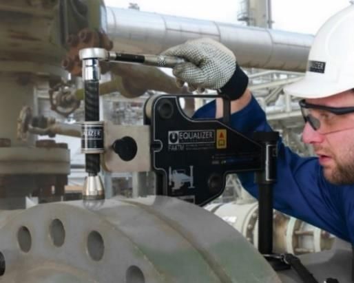
Abstract

         This Final Design Review document encompasses the entirety of a sponsored senior project
which was conducted by a group of four undergraduate mechanical engineers at California
Polytechnic University San Luis Obispo. The primary sponsor of this project was Solar Turbines,
a subsidiary of Caterpillar Incorporated. Solar Turbines is in the business of development and
application of modern-day energy solutions with a large focus on gas powered turbines. Cal Poly
acted as a supplemental support of this project and provide the students with mentorship as well
as access to its state-of-the-art facilities for the development of an innovative solution to the design
challenge submitted by Solar Turbines. The submittal states a desire to improve the deployment
timeline of Solar Turbines’ Titan 130 Gas Turbine Mobile Power Unit. This unit hosts a split drive
train with a turbine mounted on one semi-trailer (driving trailer) and a generator mounted on
another semi-trailer (driven trailer). These two trailers must be accurately aligned and securely
fastened, currently taking roughly 12 hours. Seven of these hours account for aligning and leveling
the two trailers and five hours account for securing the trailers using tension bolt fasteners. The
process is desired to be reduced to 4 hours without compromising the strength of the connection
points. The specified alignment tolerance of the trailers was given as + ¼ inch. The primary
stresses in the connection are due to the torsional load resulting from the rotation of the turbine.
There are two load conditions that were factored into the design: the normal operating load and
the short circuit load. The normal operation load of #### ft-lbf is the torque to be experienced by
the bolts as a result of the normal operation of the turbine. The short circuit load (#### ft-lbf) is
the resulting torque the system undergoes should the generator seize. This document initially
presents the background research and function identification processes followed by the ideation
process used to develop various solutions to the problem. The final selection processes are also
laid out in detail with the final solution chosen being a hydraulically actuated form of alignment
using hydraulic arms and wedge connections between the trailers. Critical component dimensions
were then confirmed using hand calculations and ANSYS to conduct FEA. Manufacturing and
assembly plans including a bill of materials for a full prototype are provided. In addition, testing
plans which can be applied to any scale of prototype are also provided. Due to the emergence of
Covid-19 during the third phase of the project, prototype development was unable to be completed.
Instead further ANSYS analysis (Rigid Body Dynamic) was done in order to further support the
solution provided. The goal of this final document is to provide Solar Turbines with all material
listed in the Scope of Work agreement and easily lay out prototype development and testing plans
that can be used by Solar Turbines if they decide to build a prototype themselves.

                                                                                                    U-3
1.0 Introduction .................................................................................................................... 5
2.0 Background ..................................................................................................................... 6
   2.1 Overview of the Design Challenge ...........................................................................................6
   2.2 Existing Products/Designs .......................................................................................................8
   2.3 Patent Search Results ............................................................................................................ 10
   2.4 Technical Literature .............................................................................................................. 12
   2.5 Other Related Research ......................................................................................................... 14
3.0 Objective........................................................................................................................ 16
   3.1 Problem Statement ................................................................................................................ 16
   3.2 Boundary Diagram ................................................................................................................ 16
   3.3 Quality Function Development .............................................................................................. 17
4.0 Project Management ...................................................................................................... 19
5.0 Conclusion .................................................................................................................... 22
References .......................................................................................................................... 23

                                                                                                                                       U-4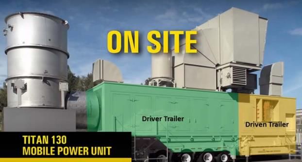
1.0 Introduction

         This document is a Final Design Review done by a group of four Cal Poly undergraduate
Mechanical Engineers for Solar Turbines regarding their Mobile Power Unit Trailer Connection
Project. Solar Turbines is a subsidiary of Caterpillar Incorporated focusing on the development
and application of modern-day energy solutions to various industries worldwide. One product
Solar Turbines is known for is their industrial gas turbine. From mid-sized to large-scale
applications there are over 15,000 units operating in over 100 countries worldwide [1]. The focus
of this project is specifically on the Titan 130 Gas Turbine Mobile Power Unit model which allows
for the delivery of high-quality power generation to temporary sites as well as sites located in
harsher environments. The current design utilizes a split drivetrain configuration with a driver
(turbine) semi-trailer and driven (generator) semi-trailer. These two trailers are transported to site
for deployment. On site, the generator trailer is placed in the desired position to be used as a
reference point for alignment. The turbine trailer is then aligned with the generator trailer. The
current method of alignment is multiple attempts at reversing the driving trailer into position with
a spotter guiding the truck driver. Once aligned to the desired tolerances of + ¼ inch the two trailers
are then jacked up level into place and secured using eight tension bolts. The tension bolts are
tensioned using standard hand tools. The total process takes roughly 12 hours. Through the
sponsorship of this project Solar Turbines hopes to reduce the process time to 4 hours, and thus
reduce the total time of the deployment process.

        This document will present the final design solution to the design challenge. The entire
process of concept generation is laid out. All the research conducted by the team to better
understand the nature of the design challenge is also laid out in the document. The final design is
presented in detail in order to show that it can reduce the time to align and attach the two trailers.
Specific components of the proposed system are also analyzed, and final dimensions are given.
Due to the emergence of Covid-19 during the third quarter of the project the manufacturing and
testing of a scaled down prototype was unable to take place and so the scope of the project was
changed to accommodate for that fact. Everything previously created in preparation of prototype
development will still be provided in the document along with an additional chapter which includes
additional Ansys Analysis (Rigid Body Dynamic) as well as notes on any modifications made to
the design since the Critical Design Review. The new goal of this document is to provide Solar
Turbines with the information they need to make an informed decision on whether to follow
through on prototype development and testing of this system.

                                                                                                   U-5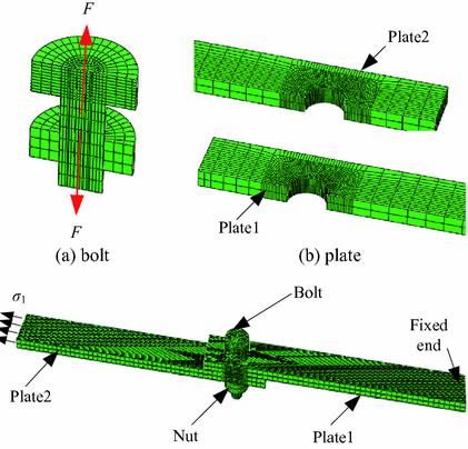
2.0 Background
       This chapter introduces the design challenge and as well as the extensive research
conducted by the team to better understand the challenge. The research was broken down as
follows:
    1. Existing products: exploring current products that are used in other industries
    2. Patents: exploring current solutions/designs for aligning and rigidly attaching heavy
       loads.
    3. Other related research: exploring possible products/design that could be integrated into
       future possible solutions.
Each of the research aspects above will be explained extensively in the following sections.

2.1 Overview of the Design Challenge
        Solar Turbines is a leading provider of energy storage solutions for both the power
generation and oil & gas markets. One of their products is the Titan 130 Gas Turbine Mobile Power
Unit (T130GMPU). The T130GMPU consist of a turbine and a generator. Both components are
built into custom semi-trailers as shown in Figure 1.

                     Figure 1. Titan 130 Gas Turbine Mobile Power Unit [1]

         As of now, it takes approximately 12 days to commission the T130GTMPU. One of the
crucial steps in the commissioning process is aligning the two trailers to a high degree of accuracy
and then rigidly connecting them. This step can take up to 12 hours. Table 1 show a rough estimate
of the time it takes for each step of the total process.

                                                                                                U-6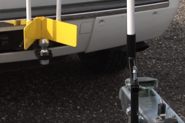
Table 1. A rough time study of the alignment and bolting process
                             Alignment Steps                            Time (hour)

                1. Backing the Turbine trailer into the generator                #
                       trailer within the required tolerance.
             2. Bolting the two trailers together. This step involves            #
                                  8 Tension Bolts.

        The first step in the alignment process is to set up the driven trailer (generator) on jacks.
After securing the driven trailer at the desired location and height, the driver trailer (turbine) is
backed into the stationary driven trailer. The two trailers must be within the tolerance required for
the studs to clear and for the nuts to be installed without seizing. The holes on the flanges in
question must be parallel otherwise the current hardware in use will not clear properly. Solar
Turbines disclosed this tolerance as a less than #-inch horizontal offset. After being aligned,
hydraulic jacks are used to level the two trailers together, though this step in the process will not
need to be addressed by the proposed design. Finally, the two trailers are bolted together using 8
tension bolts (4 on each side). Each tension bolts contains 12 bolts as shown in Figure 2 below.
The purpose of the tension bolts is to meet the strength requirements while still allowing them to
be fastened using standard hand tools.

                 Figure 2. Side view of the connection and the tension bolts [1]

                                                                                                 U-7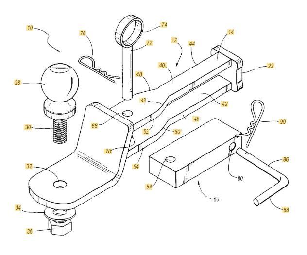
2.2 Existing Products/Designs
With extensive research the team was unable to find any existing products and designs that
were specific to the proposed project. Due to the driver and driven trailers both being massive the
team agreed to search for similar products relating to aligning and securing heavy objects. Various
methods and procedures were researched. The team found 5 ideas that were determined to be most
relatable to the design objective. One similar product discovered was the 5 Point Six-directional
system. This tool helps align mobile homes with their foundation. In addition, the Never Miss
Hitch tool was found to be a simple yet effective way for reversing and guiding a hitch to its
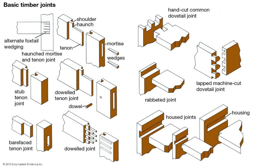
connection. Another method that was investigated was how pipe flanges are aligned using a tool
designed purposely for adjustment during alignment. There were 3 tools that were found to be very
useful during the alignment process. The FA4TM, Broad-Head Bull, and Gearench TITAN Flange
aligning tools provide a similar function. They are used to align flanges together when the hole is
partially aligned. The full list of these researched products including images can be found in Table
2 below.
Table 2. Existing Designs
Description of Design Design
5 Point Six-Directional System:
This tool is used to help move and align mobile
homes. This make it easy to move objects in the
x, y, and z plane [2].
U-8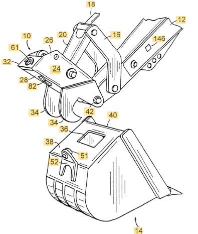
Never Miss Hitch:

This tool is used to assist the driver that is trying
to reverse and connect an object to a hitch [3].

                                 Table 2. Existing Designs (Continued)

FA4TM:
This tool is used during the final adjustment
process of alignment of large flanged pipes. As
shown in the figure this tool hooks into a hole on
one of the flanges to help you mechanically
adjust the alignment of the hole [5].

1-1/4'' (32 MM) BROAD-HEAD
BULL:
This specialized tool helps in the alignment
process for any object that will need bolt holes
aligned. These tools help you align flanges so that
the holes meet together [6].

Gearench TITAN 2 in. Flange
Aligning Tool:

This specialized tool helps in the alignment
process for holes. This tool can be used with
plates, flanges, or with any two surfaces being
bolted together. The tool is inserted into the
partially aligned hole and with adjustment it can
be pushed through to help align [4].

                                                                         U-9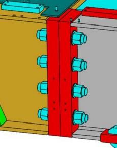
2.3 Patent Search Results
        As part of the mission to better understand the design challenge, the team decided to
perform a patent search. This research was intended to further explore current solutions to the
problem. While these patents are not directly applicable to the project, they provide ideas for
current methods of alignment and attachment which could possibly be scaled up to suit the project.
An example is patent US5371926A, which is for a shoe clasp. While not feasible for this project,
a similar method of attaching and tensioning the trailers could be applied. Hydraulic attachment
options were also examined to explore how hydraulic components could possibly be integrated
into the design. Shown below in Table 3 are some relatable patents found with a brief explanation.

                                    Table 3. Similar Patents
 Name                 Explanation             Figures /drawings

  US3136017A           This spring-loaded
    Releasable          device is inserted
 Fastening Device      through an oblong
   Actuated by           hole and turned
     Rotation           ninety degrees to
        [7]              provide tension.

                       Designed for shoe
   US5371926A
                        straps, this device
   Tension Lock
                           uses a cam to
     Buckle\
                       tension two bodies
        [8]
                           to each other.

                                                                                             U-10
This device is used
to attach implements
US6902346B2 to heavy equipment.
Hydraulic Coupler A hydraulic cylinder
[9] latches two hooks
around mating pins
on the implement.
Table 3. Similar Patents (Continued)
U-11This uses a hook
system to attach a
tool to a piece of
USRE37320E1
heavy equipment.
Hydraulic Latch
The hooks are used
Pin Assembly
to take a majority of
[10]
the load while a pin
is used to keep them
in place.
This is used to help
align a truck and
trailer. The truck is
backed up close to
the trailer and the
US6863294B1
top pin is pulled.
Easy Alignment
This allows the hitch
Trailer Hitch
to be pulled out and
[11]
rotated to align with
the hitch. Once it is
attached, the truck is
backed up and the
pin is reinserted.
2.4 Technical Literature
To examine possible future designs and better understand the challenge, additional
technical research was performed. Alignment done quickly with a high degree of tolerance was
the main aspect of the design Solar Turbines emphasized. There were multiple articles on the use
of electronic equipment paired with GPU based algorithms to accurate align various objects. Two
such articles included one article on “precise robotic assembly” [12] as well as an article on a “fast
and high-performance algorithm based on multi-vector quaternions” [13]. From these articles it
was decided that electrical components paired with low to high level processing units could
potentially mitigate many of the alignment issues. A more mechanical approach to alignment was
found in an article from the Mechanical Engineering Center at the High Energy Accelerator
Research Organization based in Japan. This article described “the use of inclinometers along with
a pair of offset bars to align objects with a certain degree of accuracy” [14]. In order to understand
the effect of bolting misalignment, an article by Wenguang Liu was read. He used an “numerical
method to investigate the effects of bolt misalignment on the stress distribution around the plate
hole” [15]. He found that the stress concentration increases around the edge of the hole when the
U-12bolt and the hole are misaligned [15]. Also, he found that the peak stress values occur at “α = 0°,
90°, 180°, 270°” which is similar to the stress concentration zone during perfect alignment [15].
Figure 3. Finite Element Analysis model [15]
In exploration of methods of decreasing the time to fasten the trailers, alternative methods
of attachment were explored. An article was found describing different types of hand fasteners,
which could possibly be scaled up to fasten larger objects. These fasteners could also be fitted with
hydraulic actuators to adapt them to the large scale of this project. Some examples of alternative
fasteners include lever actuated, slide actuated, and turn operated fasteners [16].
In order to expand the team’s knowledge of steel joints/connections, a document by Dr.
Seshu Adluri, who is a professor at Memorial University, is being referenced. In this document,
Dr. Adluri shows typical steel connections that are used in many industries [17]. These existing
designs will help in the derivations/development of a better steel connection which would reduce
the time of bolting.
Various industry standards were researched in addition to the research already completed.
This was an important step to be done prior to the design process as Solar Turbines puts priority
on the safety of their workers and potential users. The industry standards referenced were those
set by two major entities OSHA (Occupational Safety and Health Administration) and ASME (The
American Society of Mechanical Engineers). Because worker safety is of heavy importance the
OSHA standards played a key role in ensuring the team’s design meets the general safety
requirements of both operation and construction. Within the OSHA standards, two listed
publications were referenced. OSHA2236 Industry Standards for Materials Handling was
referenced due to the heavy weights involved in the alignment process [18]. While much of this
document referenced training and other aspects that Solar Turbines themselves would handle,
reading through this standard reminded the team to not extend prefabricated components beyond
their intended ratings. OSHA3080 provides general standards for the use of hand and power tools
[19]. This standard was used to ensure that the equipment workers will be expected to use in the
U-13setup and operation of our design would not be used in an improper fashion. This was done by
examining what the typical approach to such equipment is in industry.
Hydraulics came up as a potential mechanical system to provide mobility in the alignment
solution. ASME’s Hydraulic Fluids: A Guide To Test Selections and Use [20] was used as a
reference to further expand the team’s knowledge on potential issues that selecting a hydraulic
system might pose, especially in varying weather conditions. The biggest issue that stood out
within this document was the fact that no hydraulic cylinder perfectly contains the fluid thus a very
small amount of internal leakage of the fluid over time is expected. This led the team to the
conclusion that though good for mobility, the hydraulic system could not replace bolts as the sole
fasteners.
2.5 Other Related Research
To expand the knowledge about alignment, the team began researching some other
methods of alignment. One method found during research was the use of timber joints as shown
in Figure 4. Timber joints are a common example of mechanically aligning and attaching two
objects rigidly and permanently.
Figure 4. Timber Joints [21]
After looking thoroughly at each timber joint, the team realized that having sloped surfaces
could help align objects. For example, combining dowelled and dovetail joints could help the team
generate future designs to overcome the design challenge. Furthermore, the team investigated
different sloped/tapered surfaces (three-shapes) as shown in the Figure 5 below. These different
U-14shapes could be used to generate tapered connection joints which could apply to the alignment of
the two trailers.
Figure 5. 3-D tapered shapes [22]
Some of the most common devices to rigidly attach two objects together are latches. There
are many different types of latch mechanisms as shown in Figure 6; however, they all achieve the
same goal of locking two objects together. Unfortunately, these latches do not apply any tension
between the two objects unless a spring is integrated into the latching mechanism.
Figure 6. Different types of latches [23]
All the products covered in this section helped us generate ideas that could possibly be integrated
into the solution to the design challenge.
U-153.0 Objective
This section includes the problem statement of the design challenge proposed by Solar
Turbines. In addition, the boundary diagram and a description of the scope of design challenge is
presented. This chapter will end by covering the quality function development (QFD) chart which
includes the engineering specifications based on the customer needs and wants.
3.1 Problem Statement
Currently Solar Turbines’ Titan 130 Gas Turbine Mobile Power Units need to be
aligned and bolted together manually, taking about 12 hours total. Technicians and operators need
a system or tool developed to quickly, accurately, and securely align and attach the driving trailer
to the driven trailer. The goal is to reduce installation time to 4 hours without compromising the
integrity of the connections.
3.2 Boundary Diagram
For this project, the initial conditions proposed by Solar Turbines will be such that the
driven trailer is fixed in a stationary position. As seen in Figure 7 the driving trailer will then be
reversed to meet and align with the driven trailer. Once an alignment tolerance of + ¼ inch is met,
the two trailers will be rigidly attached. The area in which the tension bolts are currently used to
secure both trailers will be the primary area of focus in the initial design phases. This boundary
area will also be where any modifications might occur which would change the structure of the
trailers.
U-16Figure 7. Boundary Diagrams.
3.3 Quality Function Development
Table 4 lists some necessary engineering specifications. This table includes target “goal”
values of the final design proposed. The risk column indicates the expected difficulty in attaining
the target value within tolerance (High [H], Medium [M], Low [L]). These customer specifications
will also be tested using the methods specified in the compliance column, based on the type of
measurement. Methods of compliance include Analysis (A), Testing (T), Similarity to Existing
Designs (S), and Inspection (I).
Meeting the proposed time targets as well as the alignment tolerances were aspects of the
design that were given a high risk because they are the most critical specifications. The
manufacturing and process cost, number of operators, as well as manufacturing time were given
low risk because they are trying to be minimized, but they are not critical quantities. The weather
resistance was also given a low risk because potential design solutions do not include weather-
sensitive components. The size and stress resistance requirements were given a medium risk
because they must be considered but are attainable specifications.
Table 4. Engineering Specifications
Spec. Specification Requirement or Target
Tolerance Risk Compliance
# Description (units)
1 Time to Align # Max H A,T,S
2 Time to Attach # Max H A,T,S
3 Manufacturing Cost Minimize - L A,S
4 Number of Operators # (operators) +0/- 1 L S
5 Manufacturing Time # (weeks) Max L A,S
6 Process Cost Minimize - L A,S
7 Stress Resistance Target Loads Min M A
-50 to 100℃
8 Weather Resistance Resistant to Sand +/- 10℃ L A
10-year life
Minimize if Beyond
9 Size - M I
Trailer Footprint
10 Alignment Tolerance +/- 0.25 - H A,T,S
U-17This table is a method of determining what the actual problem to be solved is, as well as
how the different requirements correlate with one another. The QFD table also lists the customers
this product would involve, including the operators, manufacturers, financial officers, engineers,
and the end MPU users. The table then lists the needs and wants of the customers and ranks how
much each customer values these needs/wants. The current system’s performance is used as a
benchmark to rate potential solutions. The interactions and correlations between these lists are
useful in determining what the important areas of focus are.
U-184.0 Project Management
The development of an innovative solution for Solar Turbines’ proposed project will be
following a strict timetable. As shown on the Gantt chart attached in Appendix (B) there are dates
by which certain milestones of the project need to be completed. As this project will take place
over the course of three consecutive quarters, each quarter will have its own major milestones. The
cumulative milestone of each quarter and a brief description of what that each quarter will entail
is listed below as well as visually shown in Appendix (C).
Quarter 1: Preliminary Design Review
Major Milestones:
(10/17/19) Completion of Scope of Work Document
(11/21/19) Preliminary Design Review
During the first quarter, the project was selected, and the team was formed. The need of
the customer was then defined which led to the creation of the mentioned problem statement. This
problem statement was then used to create the QFD chart (Appendix A). The background research
had been ongoing, but more specific research was completed once the engineering specifications
were defined. Various design ideas were developed during the ideation phase of the design
process. It is important to note these ideas were at first created with maximum quantity being the
end-goal. The mass quantity of ideas was then broken down into how each desired function was
being met the by the proposed concept. These function concepts were then used to develop Pugh
and Morphological Matrices which in turn were used to develop a final Weighted Decision
Matrix. This Weighted Decision Matrix was used to select a final concept. Some basic calculations
were done to ensure the selected concept would be able to meet required loads. The normal
operating and short circuit torsion loads were considered. Once it was determined that the concept
was feasible a rough CAD model was developed. This CAD model was then used to develop a
final concept prototype. It is important to note this prototype was merely a proof of concept and
will not be the prototype undergoing extensive testing.
Quarter 2: Critical Design Review
Major Milestones:
(1/16/20) Interim Design Review
(2/17/20) Critical Design Review
(3/13/20) Manufacturing & Test Review
During this quarter majority of the design analysis was conducted. A final CAD model was
developed based on various analysis. FEA analysis was conducted on various models of proper
design dimensions in order to justify the design dimensions and part sizing. Though the whole
process could not be modeled at this time in FEA each area of concern received an FEA approach
to verify the initial hand calculations. The bolts ended up being designed to take both the normal
operating condition as well as the short circuit condition with the Wedges being designed as a
U-19redundant safety feature with respect to the short circuit loads. A manufacturing plan was created
including a bill of materials from which parts will be ordered.
Note: In order to include an easy comparison in how the project changed at the beginning of the
third quarter the expected milestones and activities are listed below follow by the actual layout the
quarter was given.
Expected Quarter 3: Final Design Review
Major Milestones:
(4/28/20) Verification Prototype Sign Off
(5/19/20) Design Verification Plan Sign Off
(5/29/20) Senior Design Expo
During this quarter majority of the manufacturing of the final prototype will be executed.
The manufacturing is expected to adhere to the following schedule:
1. Manufacture scale model of end of trailers
2. Manufacture scale model of wedges
3. Cut holes for wedges and fasten the wedges to the turbine trailer.
4. Create roller members for lateral mobility of the generator trailer
5. Weld contact areas for latching mechanism onto trailer
6. Create any additional member arms needed for the hydraulic system and support of the
structure.
To test the final prototype the team plans to scale the trailer models to a size which would
allow for alignment to be demonstrated. This idea would give one of the best representations how
the final product may operate. A pulley system is under currently under consideration as described
in the design verification plan section.
After finalizing the testing method, thorough testing of this prototype will be conducted to
ensure it meets the requirements laid out in the early design phases. Once testing is complete the
project itself will be presented at the Senior Design Expo, though technical specifications will be
limited in order to protect Solar Turbines’ intellectual property.
Actual Quarter 3: Final Design Review
Major Milestones:
(5/8/2020) Review of Manufacturing and Test Plans with Solar Turbines
(5/22/2020) Review of User Manual with Solar Turbines
(5/30/2020) Completion of Additional Ansys Analysis
(6/5/2020) Submittal of Final Design Report
(6/12/2020) Final Presentation of Project to Solar Turbines
U-20As mentioned previously in chapter 6 of this document there were some major changes in the scope
of work for this project due to the emergence of Covid-19. The quarantine had a major effect on
the end goal of the project due to the team’s inability to access machine shops for the
manufacturing and testing of the prototype. With many local shops having to close the outsourcing
of manufacturing as well also was deemed unfeasible. Instead more importance was placed upon
the manufacturing and test plans as well as the user manual to be provided in the appendices of the
final report. In addition, further Ansys analysis was conducted in attempt to model the whole
system and get similar observations that could be achieved through the testing of a prototype. In
order to ensure that each document was up to the standards of Solar Turbines review sessions were
held with the Solar sponsor’s in order to receive feedback immediately on those documents.
U-215.0 Conclusion
As explained in this Final Design Report, the primary goal of this project is the creation of
a system to reduction of time in the alignment and attachment of the two trailers used in the Titan
130 Gas Turbine Mobile Power Unit. The system developed utilizes a combination of sliding
Teflon on Teflon sheets, wedges and a hydraulic system to align the trailers. After the alignment
tolerance of ¼ of an inch is met, bolts will be used to rigidly secure the two trailers. The force to
engage and disengage the wedges will be provided by the hydraulic system. Due to the degradation
of hydraulic strength primarily due to fluid loss, bolts were deemed necessary to provide the
consistent tension force after the wedges are engaged. Given the provided assumption that the
truck driver will be capable of getting the trailer within +/- 3.5 inches of the desired tolerance, the
wedges themselves will suffice to achieve the final alignment. The total deployment process will
be reduced to a timeframe of less than four hours. Analysis of critical components as well as rigid
body dynamics analysis of the whole system were provided in this document. As mentioned Covid-
19 prevented the team’s ability to manufacture and test a prototype; however, Manufacturing,
Assembly, and Testing documents are provided in the report/appendices to allow Solar Turbines
to develop and test their own prototype if they choose to do so.
U-22References
[1] Solar Turbines, “About Us”. https://www.solarturbines.com/en_US/index.html
[2] Six-Directional Systems, https://www.perfectaline.com/Multidirectionalsystems.htm
[3] Never Miss Hitch: Trailer Hitch Alignment Guide.
https://www.youtube.com/watch?v=6d75SHuYNkI.
[4] “Gearench TITAN 2 in. Flange Aligning Tool (Individual).” John M. Ellsworth Co. Inc.,
https://www.jmesales.com/gearench-titan-2-in-flange-aligning-tool-
individual/?action=select&sku=GRFT2426&gclid=Cj0KCQjwuZDtBRDvARIsAPXFx3B
OYX8YHLkB1W9Gwbgc5V0kd1yxAQHkKo4OglWndHrFYAOpS_Et1IIaAt-
rEALw_wcB
[5] “Equalizer International Ltd.” FA4TM Mechanical Linear & Rotational Flange Alignment
Tool – Equalizer International, https://www.equalizerinternational.com/products/fa4tm.
[6] https://www.digikey.com/product-detail/en/klein-tools,-inc/3255/3255KT-.
[7] Preziosi, J. (1961). Fastening device. US3136017A. Google Patents. 10/16/2019.
[8] Van Noy, A. (1993). Tension lock buckle. US5371926A. Google Patents. 10/16/2019.
[9] Steig, K. (2002). Hydraulic Coupler. US6902346B2. Google Patents. 10/16/2019.
[10] Horton, L. (1996). Hydraulic latch pin assembly for coupling a tool to a construction
equipment. USRE37320E1. Google Patents. 10/16/2019.
[11] Bonham, B. (2004). Easy alignment trailer hitch. US6863294B1. Google Patents.
10/16/2019.
[12] Z. Qin, P. Wang, J. Sun, J. Lu and H. Qiao, "Precise Robotic Assembly for Large-Scale
Objects Based on Automatic Guidance and Alignment," in IEEE Transactions on
Instrumentation and Measurement, vol. 65, no. 6, pp. 1398-1411, June 2016.
[13] D. Xu, P. Jiang, Y. Zhang, S. Fan and G. Wang, "Fast and high precision alignment
algorithm based on multi vector," 2018 IEEE/ION Position, Location and Navigation
Symposium (PLANS), Monterey, CA, 2018, pp. 505-509. Inclinometer
[14] “Self-Calibrated In-Process photogrammetry for large raw part measurement and alignment
before machining “ (Open Access) Mendikute, Alberto (IK4-Ideko, Basque Country;
20870, Spain); Yagüe-Fabra, José A.; Zatarain, Mikel; Bertelsen,
Álvaro; Leizea, Ibai Source: Sensors (Switzerland), v 17, n 9, September 9, 2017
[15] Liu W., Lin W. (2018) Effects of Bolt Misalignment on Stress Around Plate Hole. In:1
Tan J., Gao F., Xiang C. (eds) Advances in Mechanical Design. ICMD 2017.
Mechanisms and Machine Science, vol 55. Springer, Singapore
[16] “Quick-Operating Fasteners.” Machine Design, 31 Mar. 2013,
https://www.machinedesign.com/basics-design/quick-operating-fasteners.
[17] Adluri, Seshu. “Typical Steel Connections”. Memorial University.
a. https://www.engr.mun.ca/~adluri/courses/steel/ppt%20files1/Topic%20Connections%20-
typical%20joints.pdf
[18] “OSHA 2236 Materials Handling (Heavy Lifting).” OSHA Industry Standards,
www.osha.gov/Publications/OSHA2236/osha2236.htmlMaterials Handling (heavy
Lifting).
U-23[19] “OSHA 3080 Hand/Power Tools.” OSHA Industry Standards,
www.osha.gov/Publications/osha3080.html hand/power tools.
[20] Radhakrishnan, M. Hydraulic Fluids: a Guide to Selection, Test Methods, and Use.
ASME Press, 2003.
[21] Encyclpoaedi Britannica, “Time joints” . https://www.britannica.com/technology/joint
carpentry
[22] Ponting,Anuschka.“Geometryof 3D shapes-Lesson2b-Pyramids”. Steemit .https://stee
mit.com/ mathematics/ @apteacher/geometry-of-3d-shapes-lesson-2b-pyramids
[23] Ojop Sweden. “Latches Ojop”.
a. https://www.ojopsweden.com/productcategory/ojoptoggle-latches/
[24] Selected Concept video by the team. https://www.youtube.com/watch?v=G_YBsMoaJr4
U-24U-25
You can also read