A four-qubit germanium quantum processor
←
→
Page content transcription
If your browser does not render page correctly, please read the page content below
A four-qubit germanium quantum processor

                                                                         N.W. Hendrickx,1, ∗ W.I.L. Lawrie,1 M. Russ,1 F. van Riggelen,1 S.L. de Snoo,1
                                                                              R.N. Schouten,1 A. Sammak,2 G. Scappucci,1 and M. Veldhorst1, †
                                                        1
                                                          QuTech and Kavli Institute of Nanoscience, Delft University of Technology, Lorentzweg 1, 2628 CJ Delft, The Netherlands
                                                    2
                                                        QuTech and Netherlands Organisation for Applied Scientific Research (TNO), Stieltjesweg 1, 2628 CK Delft, The Netherlands
                                                                       The prospect of building quantum circuits using advanced semiconductor manufacturing positions
                                                                    quantum dots as an attractive platform for quantum information processing. Extensive studies
                                                                    on various materials have led to demonstrations of two-qubit logic in gallium arsenide, silicon,
                                                                    and germanium. However, interconnecting larger numbers of qubits in semiconductor devices has
                                                                    remained an outstanding challenge. Here, we demonstrate a four-qubit quantum processor based
arXiv:2009.04268v1 [cond-mat.mes-hall] 9 Sep 2020

                                                                    on hole spins in germanium quantum dots. Furthermore, we define the quantum dots in a two-
                                                                    by-two array and obtain controllable coupling along both directions. Qubit logic is implemented
                                                                    all-electrically and the exchange interaction can be pulsed to freely program one-qubit, two-qubit,
                                                                    three-qubit, and four-qubit operations, resulting in a compact and high-connectivity circuit. We
                                                                    execute a quantum logic circuit that generates a four-qubit Greenberger-Horne-Zeilinger state and
                                                                    we obtain coherent evolution by incorporating dynamical decoupling. These results are an important
                                                                    step towards quantum error correction and quantum simulation with quantum dots.

                                                       Fault-tolerant quantum computers utilizing quantum              for a quiet qubit environment [25], and low disorder for
                                                    error correction [1] to solve relevant problems [2] will rely      reproducible quantum dots [26, 27]. In addition, strained
                                                    on the integration of millions of qubits. Solid-state imple-       germanium quantum wells defined on silicon substrates
                                                    mentations of physical qubits have intrinsic advantages            are compatible with semiconductor manufacturing [28].
                                                    to accomplish this formidable challenge and remarkable             Furthermore, hole states can exhibit strong spin-orbit
                                                    progress has been made using qubits based on supercon-             coupling that allows for all-electric operation [29–31] and
                                                    ducting circuits [3]. While the development of quantum             that removes the need for microscopic components such
                                                    dot qubits has been at a more fundamental stage, their             as microwave striplines or nanomagnets, which is par-
                                                    resemblance to the transistors that constitute the build-          ticularly beneficial for the fabrication and operation of
                                                    ing block of virtually all our electronic hardware promises        two-dimensional qubit arrays. The realization of strained
                                                    excellent scalability to realize large-scale quantum cir-          germanium quantum wells in undoped heterostructures
                                                    cuits [4, 5]. Fundamental concepts for quantum infor-              [32] has led to remarkable progress. In two year’s time,
                                                    mation, such as the coherent rotation of individual spins          germanium has progressed from the formation of stable
                                                    [6] and the coherent coupling of spins residing in neigh-          quantum dots and quantum dot arrays [26, 27, 33], to
                                                    boring quantum dots [7], were first implemented in gal-            demonstrations of single qubit logic [34], long spin life-
                                                    lium arsenide heterostructures. The low disorder in the            times [35], and the realization of fast two-qubit logic in
                                                    quantum well allowed the construction of larger arrays             germanium double quantum dots [31].
                                                    of quantum dots and to realize two-qubit logic using two              Here, we advance semiconductor quantum dots beyond
                                                    singlet-triplet qubits [8]. However, spin qubits in group          two-qubit realizations and execute a four-qubit quan-
                                                    III-V semiconductors suffer from hyperfine interactions            tum circuit using a two-dimensional array of quantum
                                                    with nuclear spins that severely limit their quantum co-           dots. We achieve this by defining the four-qubit sys-
                                                    herence. Group IV materials naturally contain higher               tem on the spin states of holes in gate-defined germa-
                                                    concentrations of isotopes with a net-zero nuclear spin            nium quantum dots. Fig. 1A shows a scanning-electron-
                                                    and can furthermore be isotopically enriched [9] to con-           microscopy (SEM) image of the germanium quantum pro-
                                                    tain only these isotopes. In silicon electron spin qubits,         cessor. The quantum dots are defined in a strained ger-
                                                    quantum coherence can therefore be sustained for a long            manium quantum well on a silicon substrate (Fig. 1B)
                                                    time [10, 11] and single qubit logic can be implemented            [25] using a double layer of electrostatic gates and con-
                                                    with fidelities exceeding 99.9 % [12, 13]. By exploiting           tacted by aluminum ohmic contacts. A negative poten-
                                                    the exchange interaction between two spin qubits in ad-            tial on plunger gates P1-P4 accumulates a hole quantum
                                                    joining quantum dots or closely separated donor spins,             dot underneath that serves as qubit Q1-Q4, which can be
                                                    two-qubit logic could be demonstrated [14–20]. Silicon,            coupled to neighboring quantum dots through dedicated
                                                    however, suffers from a large effective mass and valley de-        barrier gates. In addition, two quantum dots are placed
                                                    generacy [21], which has hampered progress beyond two-             to the side of the two-by-two array, and the total sys-
                                                    qubit demonstrations.                                              tem comprises six quantum dots. Via an external tank
                                                       Holes in germanium are emerging as a promising alter-           circuit, we configure these additional two quantum dots
                                                    native [22] that combine favorable properties such as zero         as radio frequency (rf) charge sensors for rapid charge
                                                    nuclear spin isotopes for long quantum coherence [23],             detection. Using the combined signal of both charge sen-
                                                    low effective mass and absence of valley states [24] for           sors [33], we measure the four quantum dot stability dia-
                                                    relaxed requirements on device design, low charge noise            gram as shown in Fig. 1C. Making use of two virtual gate
2
A C D F
(0,2)T
P2 (1,1)AP 0.8
S1 0.8
20 (1,1)P 0.6
(0,1) 0.6
P3 (0,0,0,0)
P1
(P 1 +P 2 +P 3 +P 4 ) (mV)
(0,2)S 0.4 0.4
P
P
10 slow Tin
S2 (0,0,0,0) fast 0.2 0.2
P4 0 0.4 0.8
(1,0,1,0) E visibility 0 Q1 Q2 0
0 (0,1,0,1)
(0,1,1,1) 0.8 Q4 Q3
5 0.8
U 12 (mV)
B -10 (1,1,1,1) 0.6
0.6
(0,2,1,1)
0
(1,1,1,1)
0.4
P
P
SiGe (2,1,2,1) -5 0.4
-20 (1,2,1,2)
Ge 0.2
-10 0.2
SiGe (1,2,1,1) 0
-10 0 10 -10 -5 0 5 0 200 400 600 800 0 200 400 600 800 1000
(P 1 -P 2 +0.75P3 -0.75P 4 ) (mV) 12
(mV) t p (ns) t p (ns)
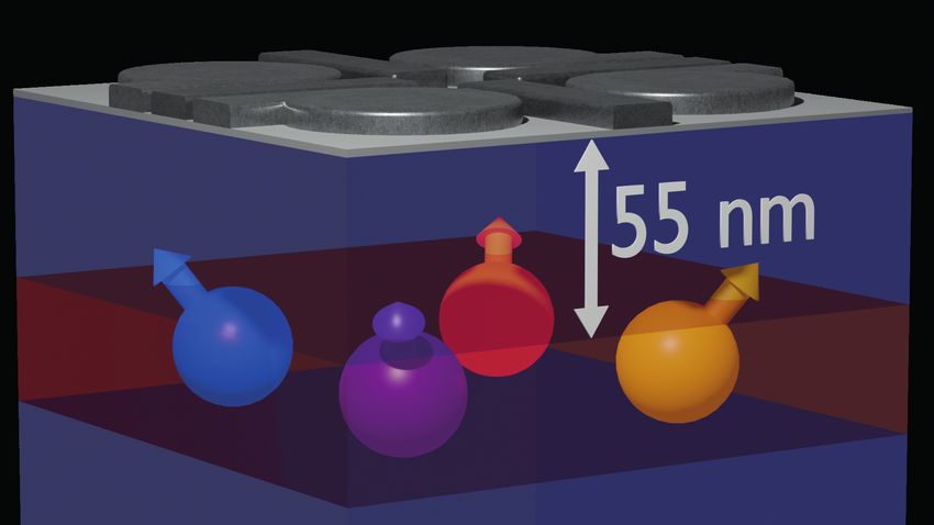
Figure 1. Four germanium hole spin qubits. (A) Scanning electron microscope image of the four quantum dot device.
We define qubits underneath the four plunger gates indicated by P1-P4. The qubits can be measured using the two charge
sensors S1 and S2. The scale bar corresponds to 100 nm. (B) Schematic drawing of the Ge/SiGe heterostructure. Starting
from a silicon wafer, a germanium quantum well is grown in between two Si0.2 Ge0.8 layers at a depth of 55 nm from the
semiconductor/dielectric interface. (C) Four quantum dot charge stability diagram as a function of two virtual gates. At the
vertical and diagonal bright lines a hole can tunnel between two quantum dots or a quantum dot and its reservoir respectively. As
a result of the virtual axes, the addition lines of the different quantum dots have different slopes, allowing for an easy distinction
of the different charge occupations indicated in the white boxes as (Q1, Q2, Q3, Q4). (D) Energy diagram illustrating the
latched Pauli spin blockade readout. When pulsing from the (1,1) charge state to the (0,2) charge state, only the polarized
triplet states allow the holes to move into the same quantum dot, leaving an (0,2) charge state (green). Interdot tunneling is
blocked for the two antiparallel spin states and as a result the hole on the first quantum dot will subsequently tunnel to the
reservoir leaving an (0,1) charge state (red), locking the different spin states into different charge states. (E) Readout visibility
as defined by the difference in readout between either applying no rotation and a π-rotation to Q2. The readout point is moved
around the (1,1)-(0,2) anticrossing of the Q1Q2 system and a clear readout window can be observed bounded by the different
(extended) reservoir transition lines indicated by the dotted lines. (F) The qubits can be rotated by applying a microwave tone
resonant with the Zeeman splitting of the qubit. Coherent Rabi rotations can be observed as a function of the microwave pulse
length tp for all qubits Q1-Q4.
axes, we arrange the reservoir addition lines of the four (1,1)-(0,1) (fast) and the extended (1,1)-(1,2) (slow) tran-
quantum dots to have different relative slopes of approx- sitions (dotted lines in Fig. 1E). When the interdot tun-
imately −1, +1, −0.75, 0.75 mV/mV for Q1, Q2, Q3, and neling into the (0,2) charge state is blocked, the hole in
Q4 respectively. Well defined charge regions (indicated the first quantum dot will quickly tunnel into the reser-
as (Q1,Q2,Q3,Q4) in the white boxes) are observed, with voir. This locks the spin state in the metastable (0,1)
vertical anticrossings marking the different interdot tran- charge state, with the decay to the (0,2) ground state
sitions. The high level of symmetry in the plot is a sign governed by the slow tunnel rate Tin between the second
of comparable gate lever arms and quantum dot charging quantum dot and the reservoir. The high level of control
energies, confirming the uniformity in this platform and in germanium allows the tuning of Tin to arbitrarily long
simplifying the operation of quantum dot arrays. time scales by changing the potential applied to the corre-
sponding reservoir barrier gates. We set Tin, Q2 = 200 µs
For the qubit readout we make use of Pauli-spin block- and Tin, Q4 = 2.4 ms (Fig. S2), both significantly longer
ade to convert the spin states into a charge signal that than the signal integration time Tint = 10 µs. We operate
can be detected by the sensors. In germanium, however, in a parity readout mode where we observe both antipar-
the spin-orbit coupling can significantly lower the spin allel spin states to be blocked (Fig. S3AB). We speculate
lifetime during the readout process, in particular when this is caused by the strong spin-orbit coupling mixing
the spin-orbit field is perpendicular to the external mag- the parallel (1,1) states with the (0,2) state, and caus-
netic field, reducing the readout fidelity [34, 36]. Here, we ing strong relaxation of the upper parallel spin state. By
overcome this effect by making use of a latched readout both increasing the interdot coupling and elongating the
process [37]. During the readout process, as illustrated ramp between the manipulation and readout point, we
in Fig. 1D, a hole can tunnel spin-selectively to the reser- can transition into a state selective readout where only
voir as a result of different tunnel rates of both quan- the |↓↑i state results in spin blockade (Fig. S3CD), with
tum dots to the reservoir. After this process, the system a slightly reduced readout visibility.
is locked in this charge state for the slow reservoir tun-
nel time Tin . We achieve this effect by pulsing into the In our experiments, we configure the system such that
area in the (0,2) charge region bounded by the extended the spin-orbit field is oriented along the direction of the3
B0
Pblocked
0.9
(rad)
3 0.5
2 0.1
control
flow
0
(rad)
3
2
control
fhigh
0
(rad)
3
flow 2
control
0
(rad)
3
fhigh 2
control
0
θ 0 2 3 0 2 3 0 2 3 0 2 3 0 2 3 0 2 3 0 2 3 0 2 3
ϕ Q1
(rad) Q1
(rad) Q2
(rad) Q2
(rad) Q3
(rad) Q3
(rad) Q4
(rad) Q4
(rad)
Figure 2. Controlled rotations between all nearest-neighbor qubit pairs. By selectively enabling the exchange inter-
action between each pair of qubits, we can implement two-qubit controlled rotations (CROTs). The pulse sequence consists of
a single preparation gate with length θ on the control qubit (labeled green), followed by a controlled rotation on one of the
resonance lines of the target qubit (labelled in red). Both qubit pairs Q1Q2 and Q3Q4 are read out in single-shot mode and
the position of the eye on top of each column indicates the respective readout pair. Each of the four main columns corresponds
to conditional rotations on a different qubit as indicated by the red dot. Rows one and two show the results for the horizontal
interaction (dark green), while rows three and four show the two-qubit interaction for the vertical direction (light green) with
respect to the external magnetic field, as indicated in the top left. Rows one and three correspond to driving the lower frequency
flow conditional resonance line, while rows two and four show driving of the other resonance line fhigh .
external magnetic field B0 = 1.05 T. This minimizes re- of gQ1 = 0.16, gQ2 = 0.24, gQ3 = 0.24, and gQ4 = 0.26.
laxation and we project all qubit measurements onto this We note that these g-factors can be electrically modu-
readout direction, thus reading out qubit pairs Q1Q2 and lated using nearby gates as a means to ensure individual
Q3Q4. Each charge sensor can detect transitions in both qubit addressability. Fig. 1F shows the single-shot spin-
qubit pairs, but is mostly sensitive to their respective up probability P↑ for each of the four qubits after apply-
nearby quantum dots. We maximize the readout visibil- ing an on-resonant microwave burst with increasing time
ity as defined by the difference between the readout of duration tp , resulting in coherent Rabi oscillations.
a spin-up and spin-down state by scanning the readout To quantify the quality of the single qubit gates, we
level around the relevant anticrossing. This is illustrated perform benchmarking of the Clifford group [39] (Fig. S4)
for the Q1Q2 pair in Fig. 1E, where a clear readout win- and find single qubit gate fidelities exceeding 99 % for all
dow with maximum visibility can be observed bounded qubits. The fidelity of Q3 is even above 99.9 %, thereby
between the (extended) reservoir transitions of the two comparing to benchmarks for quantum dot qubits in iso-
quantum dots. topically purified silicon [12, 13]. We find spin lifetimes
Coherent rotations can be implemented by applying between T1 = 1 − 16 ms (Fig. S5), comparable to val-
electric microwave signals to the plunger gates that define ues reported before for holes in planar germanium [35].
the qubits, exploiting the spin-orbit coupling for fast driv- Furthermore, we observe T2∗ to be between 150-400 ns
ing [30, 38]. We initialize the system in the |↓↓↓↓i state for the different qubits (Fig. S6A), but are able to ex-
by sequentially pulsing both the Q1Q2 and Q3Q4 double tend phase coherence up to T2CPMG = 100 µs by per-
quantum dot systems from their respective (0, 2)S states forming Carr-Purcell-Meiboom-Gill (CPMG) refocusing
adiabatically into their (1, 1)T− states. We then perform pulses (Fig. S6C), more than two orders of magnitude
the qubit manipulations, after which we perform the spin larger than previously reported for hole quantum dot
readout as described above. We observe qubit resonances qubits [29–31]. This indicates the qubit phase coher-
at fQ1 = 2.304 GHz, fQ2 = 3.529 GHz, fQ3 = 3.520 GHz, ence is mostly limited by low-frequency noise, which is
and fQ4 = 3.882 GHz, corresponding to effective g-factors confirmed by the predominantly 1/f α noise spectrum we4
A
π,fq π,fq π,fq π,fq
R R
R R
R R
B 1Q (C) 2Q (D-E) 3Q (F-I) 4Q (J) G J
↑↑↑
frequency
↓↑↑
↑↓↑ 0.6 0.6
↓↓↑
↑↑↓
P up
P up
↓↑↓ 0.2
↑↓↓ 0.2
↓↓↓
2.6 2.65 2.7 3.66 3.7 3.74
C E H K fq (GHz)
0.8
0.8
0.6 0.6 0.6
0.5
0.4 0.4
P up
P up
P up
P up
0.2 0.2 0.2 0.2
3.45 3.5 3.36 3.4 3.44 3.48 3.35 3.4 3.45 0 200 400
D F I L
0.8 0.6
0.6 0.6
0.6
0.4 0.4
P up
P up
P up
P up
0.2 0.2 0.2 0.2
3.7 3.75 3.8 3.65 3.7 3.75 4.1 4.15 4.2 0 100 200
fq (GHz) fq (GHz) fq (GHz) tp (ns)
Figure 3. Resonant one, two, three, and four-qubit gates. (A) Circuit diagram of the experiment performed in panels
C-L. All eight permutations of the three control qubit eigenstates are prepared, with R being either no pulse or a π-pulse on
the respective qubit. Next, the resonance frequency of the target qubit is probed using a π-rotation with varying frequency
fq . Finally, the prepared qubits are projected back and the target qubit state is measured. By changing the different interdot
couplings J, we can switch between resonant single, two, three, and four-qubit gates as indicated in the dashed boxes. (B)
Turning on the exchange interaction between the different qubit pairs splits the resonance frequency in two, four, and eight
for 1, 2 and 3 enabled pairs respectively. The colors of the line segments correspond to the colors in panels C-L. (C) By
turning all exchange interactions off, the qubit resonance frequency of Q2 is independent of the prepared state of the other
three qubits, resulting in an effective single-qubit rotation. (D-E) By turning on a single exchange interaction J12 (D) or J23
(E), the resonance line splits in two. (F-I), Turning on both exchange interactions to the neighboring quantum dots results in
the resonance line splitting in four, for Q2 (F), Q1 (G), Q3 (H), Q4 (I) respectively. (J) Turning on the exchange interactions
between three pairs of quantum dots J12 , J23 , J41 splits the resonance line in eight. (K-L) Resonant driving of the three-qubit
gate (K) and the four-qubit gate (L) with Q2 being the target qubit, shows Rabi driving as a function of pulse length tp ,
demonstrating the coherent evolution of the operation.
observe by Ramsey and dynamical decoupling noise spec- the two quantum dots while keeping the detuning and
troscopy (Fig. S7). This noise could originate in the nu- on-site energy of the quantum dots constant and close
clear spin bath present in germanium, which could be to the charge-symmetry point. We demonstrate CROT
mitigated by isotopic enrichment. Alternatively, it could gates between all four pairs of quantum dots in Fig. 2,
be caused by charge noise acting on the spin state through proving that spin qubits can be coupled in two dimen-
the spin-orbit coupling and it is predicted that the sen- sions. A sequence of qubit pulses is applied, as indi-
sitivity to this type of noise could be mitigated by care- cated in the diagram, consisting of a single qubit control
ful optimization of the electric field environment [40] or pulse (green) and a target qubit two-qubit pulse (red).
moving to a multi-hole charge occupancy, screening the We vary the length of both the control pulse θcontrol as
influence of charge impurities [41], potentially enabling well as the length of the target qubit pulse φQ1-Q4 , with
even higher fidelity operations. tp (φ = π) = 50 − 110 ns (details in Table S1). The
conditional rotations are performed on all four target
Universal quantum logic can be accomplished by com-
qubits (main four columns) for both the horizontally in-
bining the single qubit rotations with a two-qubit en-
teracting qubits (rows 1 and 2), as well as the vertically
tangling gate. We implement this using a conditional
interacting qubits (rows 3 and 4), by driving the |↓↓i-
rotation (CROT) gate, where the resonance frequency
|↑↓i transitions with flow (rows 1 and 3), as well as the
of the target qubit depends on the state of the control
inverse |↓↑i-|↑↑i transitions with fhigh (rows 2 and 4),
qubit, mediated by the exchange interaction J between
with Qtarget Qcontrol . We then perform a measurement
the two quantum dots. The exchange interaction be-
on both readout pairs by sequentially pulsing the Q1Q2
tween the quantum dots is controlled using a virtual bar-
(left sub-columns), and the Q3Q4 qubit pairs (right sub-
rier gate (details in Materials and Methods), coupling5
A C
Qtarget X Z(θ) X Q3 X Y2 X
UCZ UCZ
J on (t) (t)
Qcontrol X2 X2 Q2 Y2
Z(φ1) tCZ < 10 ns Q3 X X Y2 X X
Vbarrier
idle idle
= UCZ UCZ = J off (t) (t)
Z(φ2)
time Q2 X Y2 X
B D
0.8 1 0.6
0.8 τon = 130 ns
0.6 0.6
P up
P up
Q1Q2 Q2Q3 0.5 0.4
0.4 0.4
0.2 τoff = 200 ns
0.2 0.2
0 2 4 6 0 2 4 6 0 0.5 0 0.5
1 1
0.8 0.8 τon, echo = 220 ns τoff, echo = 2100 ns
0.6 0.6 0.8
P up
P up
0.4 Q3Q4 Q4Q1 0.5
0.4
0.2 0.6
0.2
0 2 4 6 0 2 4 6 0 0.5 0 5 10
(rad) (rad) 2t ( s) 2t ( s)
Figure 4. Controlled phase gate and dynamical decoupling. (A) Circuit diagram of the experiment performed in panel
B. The controlled phase gate is probed by performing a Ramsey sequence on the target qubit for both basis states of the control
qubit. The phase of the second π/2 (X) gate is swept by performing an update of the microwave phase through quadrature
modulation. Additionally, a phase update is performed on both the target and control qubit to compensate for any single qubit
phases picked up as a result of the gate pulsing to achieve a controlled-Z (CZ) gate. (B) The spin-up probability of the target
qubit (in bold) as a function of the phase θ of the second X gate for the control qubit initialized in the |↓i (blue) and |↑i (red)
state. Measurements for the inverted target and control qubits in Fig. S10. By applying an exchange pulse and single qubit
phase updates, we achieve a CZ gate at θ = 0 rad. (C) Circuit diagrams of the experiment performed in panel D. The phase
coherence throughout the two-qubit experiment is probed using a Ramsey sequence, both for the case with J on (top) and
off (bottom) and both with (orange) and without (blue) applying an echo pulse. (D) Spin-up probability as a function of the
experiment length, for the situation with exchange on (left, triangles) and off (right, circles). From the decay data we extract
characteristic decay times τ of τon = 130 ns, τon, echo = 220 ns, τoff = 200 ns, and τoff, echo = 2100 ns (details in Materials and
Methods).
A
Q3 X(tprep) Y2 X
Q2 X X Y2 X X
Q1 X X Y2 X X
Q4 X X Y2 X X
I II III IV V VI VII VIII IX
B
1
0.8
0.6
Pnorm
0.4
0.2
0
Q3Q4 0 100 200 0 100 200 0 100 200 0 100 200 0 100 200 0 100 200 0 100 200 0 100 200 0 100 200
tprep (ns) tprep (ns) tprep (ns) tprep (ns) tprep (ns) tprep (ns) tprep (ns) tprep (ns) tprep (ns)
Q1Q2
Figure 5. Coherent generation of a four-qubit Greenberger-Horne-Zeilinger (GHZ) state. (A-B) A four-qubit GHZ
state is created by applying three sequential two-qubit gates, each consisting of an X-CZ-X gate circuit. Next, a Y2 decoupling
pulse is applied, after which we disentangle the GHZ state again (circuit diagram in A). Pulses pictured in the same column
are applied simultaneously. The initial state of Q3 is varied by applying a preparation rotation of length t. For different stages
throughout the algorithm (dashed lines), we measure the non-blocked state probability as a function of t for both the Q1Q2 and
Q3Q4 readout system, normalized to their respective readout visibility. At the end of the algorithm the qubit states correspond
to the initial single qubit rotation, and the clear oscillations confirm the coherent evolution of the algorithm from isolated qubit
states to a four-qubit GHZ state. (B).6
columns) to their respective readout points. Because the gates between the different qubit pairs by adiabatically
target qubit resonance frequency depends on the control pulsing the exchange interaction using the respective vir-
qubit state, the conditional rotation is characterized by tual barrier gate. Increasing the exchange interaction, the
the fading in and out of the target qubit rotations as a antiparallel spin states will shift in energy with respect to
function of the control qubit pulse length. The pattern the parallel spin states, giving rise to a conditional phase
is therefore shifted by a π rotation on the control qubit, accumulation. We control the length and size of the volt-
for driving the two separate transitions. When driving age pulse (Fig S9) to acquire a CZ gate, in which the
the |↓↓i-|↑↓i transition of the qubit pairs used for read- antiparallel spin states accumulate a phase of exactly π
out (row 1), we apply an additional single-qubit π-pulse with respect to the parallel spin states. We demonstrate
to the preparation qubit for symmetry, since the control this in Fig. 4A-B, where we employ a Ramsey sequence to
qubit also serves as the readout ancilla. When the con- measure the conditional phase. After the exchange pulse
trol qubit is in a different readout pair as the target qubit UCZ we apply a software Z gate to both the target and
(rows 3 and 4), we can independently observe the single control qubits to compensate for individual single qubit
qubit control, and two-qubit target qubit rotations in the phases. As a result of the large range over which the ex-
two readout systems. By setting the pulse length equal change interaction can be controlled, we achieve fast CZ
to φQ = π, a fast CX gate can be obtained within ap- gates that are executed well within 10 ns for all qubit
proximately tp = 100 ns between all of the four qubit pairs (details in Table S2).
pairs.
To prepare our system for quantum algorithms, we im-
To demonstrate full control over the coupling between plement decoupling pulses into the multi-qubit sequences
the different qubits, we measure the qubit resonance fre- to extend phase coherence, as demonstrated in Fig. 4C-D.
quency as a function of the eight possible permutations To probe the effect of a decoupling pulse when exchange is
of the different basis states of the other three qubits, as on (Fig. 4D, left, triangles), we perform a CPHASE gate
illustrated in Fig. 3A-B. Without any exchange present, between qubits Q2 and Q3 and compare the decay of the
the resonance frequency of the target qubit should be in- resulting exchange oscillations as a function of the oper-
dependent on the preparation of the other three qubits, ation time for the situations with (orange) and without
as schematically depicted in Fig. 3C. When the exchange (blue) a Y2 echo pulse. We observe an extended duration
to one of the neighboring quantum dots is enabled by for the conditional phase rotations of τ = 220 ns when
pulsing the virtual barrier gate, the resonance line splits applying a decoupling pulse, compared to τ = 130 ns
in two, allowing for the operation of the CROT gate, as for a standard CPHASE gate. A more relevant situa-
is shown for both the Q1-Q2 and Q2-Q3 interactions in tion however, is the coherence of the two-qubit entangled
Fig. 3D and E respectively. When both barriers to the state. We probe this by entangling Q2 and Q3 by form-
nearest-neighbors are pulsed open at the same time, we ing the |Ψ+ i Bell state and letting the system evolve for
observe a fourfold splitting of the resonance line (Fig. 3F- time 2t (Fig. 4D, right, circles). Next, we disentangle
I). This allows the performance of a resonant i-Toffoli the system again and measure the spin-up probability of
three-qubit gate (Fig. 3K and Fig. S8), which has theo- Q3 as a function of the evolution time. Without the de-
retically been proposed as an efficient manner to create coupling pulse, we observe the loss of coherence after a
the Toffoli, Deutsch, and Fredkin gates [42]. We observe characteristic time τ = 200 ns. However, by applying
a difference in the efficiency at which the different condi- the additional echoing pulse on both Q2 and Q3, we can
tional rotations can be driven, as can also be seen from significantly extend this time scale beyond 2 µs, enough
the width of the resonance peaks in Fig. 3F-I. This is to perform a series of single and multi-qubit gates, owing
expected to happen when the exchange energy is compa- to our short operation times.
rable to the difference in Zeeman splitting and is caused
We show this by coherently generating and disentan-
by the mixing of the basis states due to the exchange
gling a four-qubit Greenberger-Horne-Zeilinger (GHZ)
interaction between the holes [43] (details in Materials
state (Fig. 5). Making use of the fast two-qubit CZ gates,
and Methods). Finally, we open three of the four virtual
as well as a decoupling pulse on all qubits, we can main-
barriers and observe the resonance line splitting in eight,
tain phase coherence throughout the experiment. We
being different for all eight permutations of the control-
perform a parity readout on both the Q1Q2 (red) and
qubit preparation states (Fig. 3J). This enables us to ex-
Q3Q4 (green) at different stages of the algorithm and nor-
ecute a resonant four-qubit gate and in Fig. 3L we show
malize the observed blocked state fraction to the readout
the coherent operation of a three-fold conditional rota-
visibility. We prepare a varying initial state by applying a
tion (see Fig. S8 for the coherent operation of the other
microwave pulse of length t to Q3, as observed in I. After
resonance lines).
applying CZ gates between all four qubits, the system
While the demonstration of these conditional rotations resides in an entangled GHZ type state at IV/V, for a
can be beneficial for the simulation of larger coupled spin π/2 preparation pulse on Q3. The effective spin state os-
systems, the ability to dynamically control the exchange cillates between the antiparallel |1010i and |0101i states
interaction allows for faster two-qubit operations [14, 16]. as a function of tprep , resulting in a high state readout
We efficiently implement controlled phase (CPHASE) for all t. The small oscillation that can still be observed7
for the Q1Q2 system, is caused by a small difference in
readout visibility for the two distinct antiparallel spin
states. Next, we deploy a Y2 decoupling pulse to echo ∗
n.w.hendrickx@tudelft.nl
out all single qubit phase fluctuations during the exper- †
m.veldhorst@tudelft.nl
iment (Fig. S11). After disentangling the system again, [1] B. M. Terhal. Quantum error correction for quantum
we project the Q3 qubit state by applying a final X (π/2) memories. Rev. Mod. Phys. 87, 307 (2015).
gate, and indeed recover the initial Rabi rotation. [2] M. Reiher, N. Wiebe, K. M. Svore, D. Wecker, M. Troyer.
The demonstration of a two-by-two four-qubit array Elucidating reaction mechanisms on quantum computers.
PNAS 114, 7555 (2017).
shows that quantum dot qubit systems can be scaled in
[3] F. Arute, et al.. Quantum supremacy using a pro-
two-dimensions and multi-qubit logic can be executed. grammable superconducting processor. Nature 574, 505
The hole states used are subject to strong spin-orbit cou- (2019).
pling, enabling all-electrical driving of the spin state, ben- [4] D. Loss, D. P. DiVincenzo. Quantum computation with
eficial for scaling up to even larger systems. Making use quantum dots. Phys. Rev. A 57, 120 (1998).
of a latched readout mechanism overcomes fast spin re- [5] L. M. K. Vandersypen, et al.. Interfacing spin qubits in
laxation due to the spin-orbit coupling. Furthermore, quantum dots and donors—hot, dense, and coherent. npj
Quantum Information 3, 34 (2017).
the ability to freely couple one, two, three and four spins
[6] F. H. L. Koppens, et al.. Driven coherent oscillations of
using fast gate pulses has great prospects both for per- a single electron spin in a quantum dot. Nature 442, 766
forming high-fidelity quantum gates as well as studying (2006).
exotic spin systems using analog quantum simulations. [7] J. R. Petta, et al.. Coherent Manipulation of Coupled
While the execution of relevant quantum algorithms will Electron Spins in Semiconductor Quantum Dots. Science
require many more qubits, the germanium platform has 309, 2180 (2005).
the potential to leverage the enormous advancements in [8] M. D. Shulman, et al.. Demonstration of Entanglement of
Electrostatically Coupled Singlet-Triplet Qubits. Science
semiconductor manufacturing techniques for the realiza-
336, 202 (2012).
tion of fault-tolerant quantum processors. [9] K. M. Itoh, H. Watanabe. Isotope engineering of silicon
and diamond for quantum computing and sensing appli-
cations. MRS Commun. 4, 143 (2014).
[10] J. T. Muhonen, et al.. Storing quantum information for
ACKNOWLEDGEMENTS
30 seconds in a nanoelectronic device. Nat. Nanotech. 9,
986 (2014).
We thank L.M.K. Vandersypen for useful discussions [11] M. Veldhorst, et al.. An addressable quantum dot qubit
and thank S.G.J. Philips for his contributions to software with fault-tolerant control-fidelity. Nat. Nanotech. 9, 981
development. M.V. acknowledges support through a Vidi (2014).
[12] J. Yoneda, et al.. A quantum-dot spin qubit with co-
grant, two projectruimte grants, and an NWA grant, all herence limited by charge noise and fidelity higher than
associated with the Netherlands Organization of Scien- 99.9%. Nature Nanotechnology 13, 102 (2018).
tific Research (NWO). [13] C. H. Yang, et al.. Silicon qubit fidelities approaching
incoherent noise limits via pulse engineering. Nat Electron
2, 151 (2019).
[14] M. Veldhorst, et al.. A two-qubit logic gate in silicon.
COMPETING INTERESTS Nature 526, 410 (2015).
[15] D. M. Zajac, et al.. Resonantly driven CNOT gate for
The authors declare no competing interests. electron spins. Science 359, 439 (2018).
[16] T. F. Watson, et al.. A programmable two-qubit quantum
Correspondence should be addressed to M.V.
processor in silicon. Nature 555, 633 (2018).
(M.Veldhorst@tudelft.nl). [17] W. Huang, et al.. Fidelity benchmarks for two-qubit gates
in silicon. Nature 569, 532 (2019).
[18] Y. He, et al.. A two-qubit gate between phosphorus donor
electrons in silicon. Nature 571, 371 (2019).
DATA AVAILABILITY
[19] M. T. Mądzik, et al.. Conditional quantum operation of
two exchange-coupled single-donor spin qubits in a MOS-
All data underlying this study will be available from compatible silicon device. arXiv: 2006.04483 [cond-mat]
the 4TU ResearchData repository. (2020).
[20] L. Petit, et al.. Universal quantum logic in hot silicon
qubits. Nature 580, 355 (2020).
[21] F. A. Zwanenburg, et al.. Silicon quantum electronics.
SUPPLEMENTARY MATERIALS Rev. Mod. Phys. 85, 961 (2013).
[22] G. Scappucci, et al.. The germanium quantum informa-
tion route. arXiv: 2004.08133 [cond-mat] (2020).
Materials and Methods [23] K. Itoh, et al.. High purity isotopically enriched 70-Ge
Tables S1 – S2 and 74-Ge single crystals: Isotope separation, growth,
Figures S1 – S11 and properties. J. Mater. Res. 8, 1341 (1993).
References (S1 - S14)8
[24] M. Lodari, et al.. Light effective hole mass in undoped Dots. Nano Lett. (2020).
Ge/SiGe quantum wells. Phys. Rev. B 100, 041304 [36] J. Danon, Y. V. Nazarov. Pauli spin blockade in the
(2019). presence of strong spin-orbit coupling. Phys. Rev. B 80,
[25] M. Lodari, et al.. Low percolation density and charge 041301 (2009).
noise with holes in germanium. arXiv: 2007.06328 [cond- [37] P. Harvey-Collard, et al.. High-Fidelity Single-Shot Read-
mat] (2020). out for a Spin Qubit via an Enhanced Latching Mecha-
[26] N. W. Hendrickx, et al.. Gate-controlled quantum dots nism. Phys. Rev. X 8, 021046 (2018).
and superconductivity in planar germanium. Nature [38] D. V. Bulaev, D. Loss. Electric Dipole Spin Resonance
Communications 9, 2835 (2018). for Heavy Holes in Quantum Dots. Phys. Rev. Lett. 98,
[27] W. I. L. Lawrie, et al.. Quantum dot arrays in silicon and 097202 (2007).
germanium. Appl. Phys. Lett. 116, 080501 (2020). [39] E. Knill, et al.. Randomized benchmarking of quantum
[28] R. Pillarisetty. Academic and industry research progress gates. Phys. Rev. A 77, 012307 (2008).
in germanium nanodevices. Nature 479, 324 (2011). [40] Z. Wang, et al.. Suppressing charge-noise sensitivity in
[29] R. Maurand, et al.. A CMOS silicon spin qubit. Nature high-speed Ge hole spin-orbit qubits. arXiv: 1911.11143
Communications 7, 13575 (2016). [cond-mat] (2019).
[30] H. Watzinger, et al.. A germanium hole spin qubit. Nature [41] E. Barnes, J. P. Kestner, N. T. T. Nguyen, S. Das Sarma.
Communications 9, 3902 (2018). Screening of charged impurities with multielectron
[31] N. W. Hendrickx, D. P. Franke, A. Sammak, G. Scap- singlet-triplet spin qubits in quantum dots. Phys. Rev.
pucci, M. Veldhorst. Fast two-qubit logic with holes in B 84, 235309 (2011).
germanium. Nature 577, 487 (2020). [42] M. J. Gullans, J. R. Petta. Protocol for a resonantly
[32] A. Sammak, et al.. Shallow and Undoped Germanium driven three-qubit Toffoli gate with silicon spin qubits.
Quantum Wells: A Playground for Spin and Hybrid Phys. Rev. B 100, 085419 (2019).
Quantum Technology. Advanced Functional Materials 29, [43] B. Hetényi, C. Kloeffel, D. Loss. Exchange interac-
1807613 (2019). tion of hole-spin qubits in double quantum dots in
[33] F. van Riggelen, et al.. A two-dimensional array of single- highly anisotropic semiconductors. Phys. Rev. Research
hole quantum dots. arXiv:2008.11666 [cond-mat] (2020). 2, 033036 (2020).
[34] N. W. Hendrickx, et al.. A single-hole spin qubit. Nature
Communications 11, 3478 (2020).
[35] W. I. L. Lawrie, et al.. Spin Relaxation Benchmarks and
Individual Qubit Addressability for Holes in QuantumYou can also read