DX235NLC-5 Demolition - Crawler Excavators - Kraemer Baumaschinen
←
→
Page content transcription
If your browser does not render page correctly, please read the page content below
Crawler Excavators

DX235NLC-5
                  Demolition
Engine power (SAE J1995)   124 kW (166 hp) @ 1800 rpm
Operational weight                               28.5 t
Max. tool weight                             1.8 ~ 2.1 t
Max. height at pin                                18 m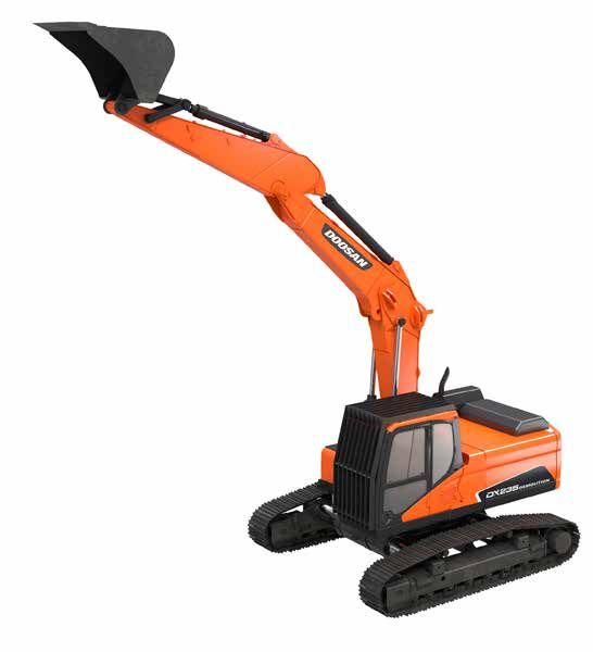
TECHNICAL SPECIFICATIONS

      ENGINE                                                                 HYDRAULIC SYSTEM
                                                                             The e-EPOS (Electronic Power Optimising System) is the brain of
      Model
                                                                             the excavator - minimising fuel consumption and optimizing the
      Doosan DL06P                                                           efficiency of the hydraulic system for all working conditions.
      Designed to deliver superior performance and fuel efficiency, the      To harmonise the operation of the engine and the hydraulics, the
      Doosan Stage IV diesel engine fully meets the latest emissions         e-EPOS is connected to the engine’s electronic control unit (ECU)
      regulations. To optimise machine performance, the engine uses          via a data transfer link.
      high-pressure fuel injectors, air-to-air inter-cooler and electronic   • The hydraulic system enables independent or combined
      engine controls. 4-Cycle Water-Cooled, Wastegate Turbocharged,            operations
      Exhaust Gas Recirculation (EGR) & Selective Catalytic Reduction        • 2 travel speeds offer either increased torque or high speed
      (SCR) with no Diesel Particulate Filter (DPF).                         • Cross-sensing pump system for fuel savings
      No. of cylinders                                                       • Auto-deceleration system
                                                                             • 4 operating modes, 4 power modes
      6
                                                                             • Flow and pressure control of auxiliary hydraulic circuits from
      Rated power                                                               control panel
      124 kW (166 hp) @ 1800 rpm (SAE J1995)                                 • Computer-aided pump flow control
      121 kW (162 hp) @ 1800 rpm (SAE J1349)                                 Main pumps
      121 kW (162 hp) @ 1800 rpm (ISO 9249)
                                                                             2 × variable displacement tandem axial piston pumps
      Max. torque                                                            Maximum flow at 1800 rpm		          2 × 206.5 l/min
      77 kgf·m (755 Nm) @ 1400 rpm                                           Pilot pump
      Idle (low - high)                                                      Gear pump
      800 [±10] - 1900 [±25] rpm                                             Maximum flow at 1800 rpm		           27 l/min

      Piston displacement                                                    Relief valve settings
      5890 cm³                                                               Pressur up        350 kg/cm²
                                                                             Travel		          330 kg/cm²
      Bore × stroke                                                          Swing		           270 kg/cm²
      100 mm × 125 mm                                                        Pilot		           40 kg/cm²
      Starter
                                                                             SWING MECHANISM
      24 V × 6 kW
                                                                             The swing mechanism uses an axial piston motor, driving a
      Batteries - Alternator                                                 2-stage planetary reduction gear bathed in oil for maximum
      2 × 12 V, 150 Ah - 24 V, 80 A                                          torque.
                                                                             • Swing bearing: single-row, shear type ball bearing with
      Air filter                                                               induction hardened internal gear
      Double element air cleaner and pre-filtered Turbo dust separator       • Internal gear and pinion immersed in lubricant
                                                                             Maximum swing speed
      FLUID CAPACITIES                                                       10.9 rpm
      Fuel tank                                                              Maximum swing torque
      339 l                                                                  8400 kgf·m
      Cooling system (radiator)
                                                                             DRIVE
      38.4 l
                                                                             Each track is driven by an independent, high-torque axial piston
      Urea (def) tank                                                        motor through a planetary reduction gearbox. Two levers / foot
      31.5 l                                                                 pedals guarantee smooth travel with counter-rotation on demand.
                                                                             The track frame protects the travel motor, brake and planetary
      Hydraulic oil tank                                                     gears. The multi-disc track brakes are spring-applied and
      200 l                                                                  hydraulic released.
      Engine oil                                                             Travel speed (low - high)
      27 l                                                                   3.0 - 5.5 km/h
      Swing drive                                                            Maximum traction
      5.0 l                                                                  27.5 t
      Travel device                                                          Maximum gradeability
      2 × 3.0 l                                                              35° / 70%

2|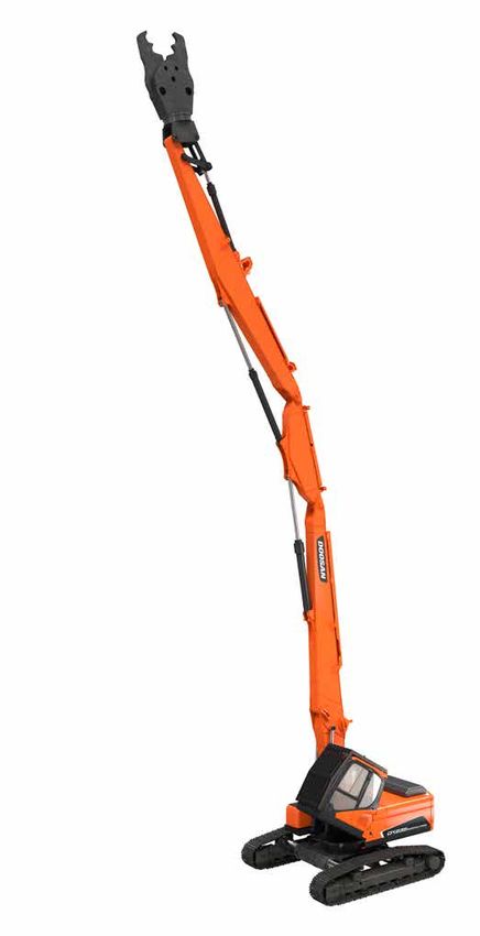
DX235NLC-5 DEMOLITION
UNDERCARRIAGE
Extremely robust construction throughout - made of high-quality,
durable materials, with all welded structures designed to limit
stresses.
• Track rollers lubricated for life
• Idlers and sprockets fitted with floating seals
• Track shoes made of induction-hardened alloy with triple
grouser
• Heat-treated connecting pins
• Hydraulic track adjuster with shock-absorbing tension
mechanism
Upper rollers (standard shoe)
2
Lower rollers
8
Number of links & shoes per side
49
Link pitch
190 mm
Overall track length
4445 mm
CAB
The air-conditioning and heating systems are integrated for
optimal climate control.
An automatically-controlled fan supplies the pressurised and
filtered cab air, which is distributed throughout the cab from
multiple vents.
The heated air suspension, adjustable operator’s seat includes a
seat belt. The operator can adjust the ergonomic seat and joystick
console separately according to his preferences.
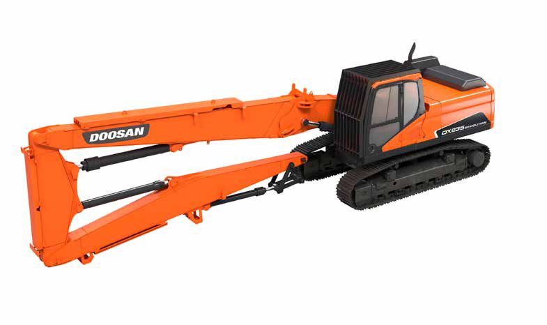
DX235NLC-5 DM with digging boom
DX235NLC-5 DM with demolition work equipment
| 3
DIMENSIONS & WORKING RANGE

      DEMOLITION CONFIGURATION
      Max. tool weight                                kg       1800 - 2100
      Variable undercarriage width                    mm       2530 - 3730
      Total weight (with crusher)*                    kg         28500
      * all models are provided with an additional counterweight

      WORKING RANGE                                                                      C

        A   Max. height at pin                        mm           18070
        B   Max. reach*                               mm           12900
        C   Max. permitted angle                       °             30                                  A
        D   Cab tilting angle                          °             30
      * the maximum reach values refer to 360°

                                                                                                 B

      TRANSPORT DIMENSIONS AND WEIGHTS
        E    Max. length                                              mm                     11460
        F    Demolition boom height                                   mm                      3050
        G    Machine length with base arm                             mm                      5970
        H    Demolition boom length                                   mm                      5490
        I    Max. height with protection grid                         mm                      3055
        J    Cab height                                               mm                     2960
        K    Transport width                                          mm                      2530
        L    Length with variable undercarriage                       mm                      3730
        M    Shoe width                                               mm                       500
             Machine weight with base boom                            kg                     28500
             Demolition boom weight                                   kg                     4000

                                  K                                              E

                                                                                     D

                                                                                     J
               I J
                                                                                                     F

                        M         L                                          G               H

4|
DX235NLC-5 DEMOLITION
DIGGING CONFIGURATION
Arm length mm 2900
Max. bucket capacity m³ 1.0
Max. tool weight kg 2200
Total weight (with crusher) * kg 26000
* without additional counterweight
WORKING RANGE A
Straight Bent
A Max. digging height mm 11200 95600 B
B Max. loading height mm 8330 6900
C Max. digging depth mm 5540 6275
Max. digging distance
D mm 9940 9470
at ground level
E Max. digging distance mm 1011 9640
* without additional counterweight
C
D
E
TRANSPORT DIMENSIONS AND WEIGHTS
F Max. length mm 9590
G Tail swing radius mm 3035
H Boom height mm 3070
I Rear overhang mm 500
J Tumbler center distance mm 3610
K Undercarriage length mm 4450
Digging boom weight kg 3000
F
G
H
I J
K
| 5©2019 DOOSAN
D4600590-EN (10-19)
www.doosanequipment.eu
Doosan Infracore Europe B.V., IBC - Pobřežní 620/3, 186 00 Praha 8-Karlín, Czech Republic
Certain specification(s) are based on engineering calculations and are not actual measurements. Specification(s) are provided for comparison purposes only and are subject to change without notice. Specification(s) for
your individual Doosan equipment will vary based on normal variations in design, manufacturing, operating conditions, and other factors. Pictures of Doosan units may show other than standard equipment.You can also read