Electricity Networks GTC Technical Guidelines - GTC Technical Guidelines and Safety Information for House Builders and Developers - ELECTRICITY ...
←
→
Page content transcription
If your browser does not render page correctly, please read the page content below

Electricity Networks

GTC Technical Guidelines
GTC Technical Guidelines and Safety Information for
House Builders and Developers

info@gtc-uk.co.uk                                     www.gtc-uk.co.uk
GTC Technical Guidelines

                           2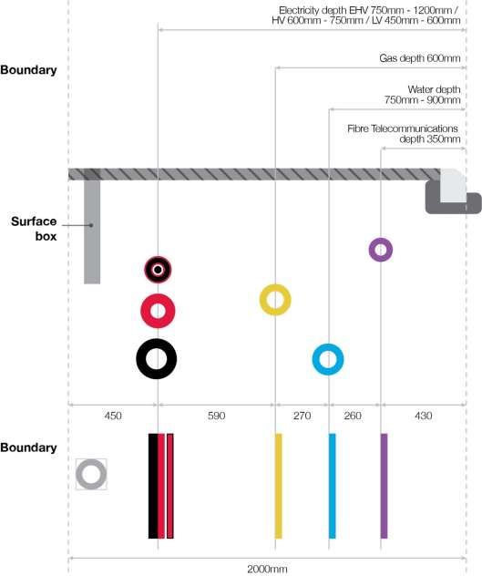
GTC Technical Guidelines

Contents
1. Introduction ...........................................................................................................................................................4

2. Communications...................................................................................................................................................5
3. Safety .....................................................................................................................................................................6

4. Definitions .............................................................................................................................................................8

5. Developer Responsibilities ............................................................................................................................... 10

6. Electricity Mains ................................................................................................................................................ 13

7. Electricity Services ............................................................................................................................................ 19

8. Multiple Occupancy Buildings ......................................................................................................................... 26

9. Non-Domestic Properties – Meter Positions .................................................................................................. 31

10. Substations ........................................................................................................................................................ 32

11. Installing Meters and MPAN Issue ................................................................................................................... 34

GE-TGI-IG-0015-Vn9.00                                                                                                                                                        3
GTC Technical Guidelines

Section One
Introduction
These guidelines provide you with information on the installation of electricity mains, services, and other parts of
our electricity networks. The guidelines also cover the safety aspects of GTC completing works onsite and specify
your responsibilities in the delivery of the electricity network.

Should you wish to contact us, the telephone number is 01359 240363

Disclaimer
Although the greatest of care has been taken in the compilation and preparation of this document, GTC respectfully
accepts no responsibility for any errors, omissions or alterations or for any consequences arising from the use, or
reliance upon the information in this document.

Section One – Introduction                                                                                             4
GTC Technical Guidelines

Section Two
Communications
Our opening hours are from 08.00 to 17:00 every weekday. The below is a list of contact details for various parts of
the customer journey.

Electricity Emergency                                         Legals
To report No Supply or Electrical Damage,                     To discuss legal transactions in relation to
please call 0800 0326990 (24 hours).                          easements and transfers over our utilities, please
                                                              contact 01359 243453 or legals@gtc-uk.co.uk.
Gas Emergency
If you can smell gas or believe a gas pipe has been           Site Installation
damaged, please call 0800 111999 (24 hours).                  To book in work on your site, please contact
                                                              0845 6022498 or gtcworks@gtc-uk.co.uk.
Fibre Emergency
To report damage to a fibre plant or OSCP,                    Meter Point Numbers
please call 02920 028726.                                     Request or query MPAN numbers, please contact
                                                              01359 245345 or mpan.requests@gtc-uk.co.uk.
Sales
To discuss your utility infrastructure solution needs         Supplier Agreements
and obtain a quotation, please contact 01359 240154           To check and change supplier/shipper contract
or sales@gtc-uk.co.uk.                                        agreements, please contact 01359 243311 or
                                                              psr@gtc-uk.co.uk.
Design
To discuss a utility design or request a variation,           Finance Queries
please contact 01359 300798 or                                For any queries regarding invoices or billing,
network_variations@gtc-uk.co.uk.                              please contact 01359 308144 or
                                                              credit.control@gtc-uk.co.uk.

Customer Services
At GTC, we are committed to providing you with excellent customer service and we encourage feedback so that we
can ensure we are making our customers happy. If you have any comments or complaints about our service,
please contact 01359 302640 or customerservices@gtc-uk.co.uk.

Section Two – Communications                                                                                       5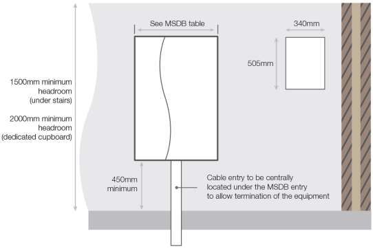
GTC Technical Guidelines

Section Three
Safety
Safe Place of Work
GTC requires a safe place of work to be provided for all its staff and contractors. Initial enquiries shall be made
seeking confirmation that the construction site is a safe place to work.

Upon arrival to site, staff and contractors shall report to the Site Manager/Representative to discuss intended
works. Prior to undertaking this work, a site-specific risk assessment will be undertaken. If, following this
assessment, the works cannot be undertaken in a safe manner, the Site Manager/Representative will be informed.
Until a safe working environment is achieved, no activities shall be undertaken.

Site Traffic Rules
All site traffic information should be made available to the team/operative when arriving on site, via a site induction
or/and during the booking in on-site stage.

Equipment and Materials
The Site Manager/Representative shall ensure their equipment and materials are operated and stored in such a
manner that they do not become a hazard within the working area of the team/operative.

Scaffold
Ensure all scaffold where the team/operatives are to work is removed prior to their arrival on site.

Welfare Facilities
In most cases, welfare facilities are to be made available on site by the Principal Contractor.

Section Three – Safety                                                                                                6

GTC Technical Guidelines

Utility Protection
Ensure all excavation works onsite are progressed using safe digging techniques. Refer to HSG47 Avoiding
Danger from Underground Services.

GTC utility plans are available via www.gtc-uk.co.uk/network-locations.

Competence
All staff and/or appointed Contractors working on behalf of GTC who attend site shall have the appropriate training,
technical knowledge and experience to discharge the intended works in a safe manner.

Construction Design Management (CDM) Regulations
GTC will act as the ‘Designer’ and ‘Contractor’ for the construction and commissioning of electricity networks on
new property developments.

The electricity mains and services that will be installed on the development will typically remain the property of the
licenced Electricity Distributor named in your quotation.

The construction team will notify the site agent’s office of what equipment has been laid and energised during the
construction phase so that other construction workers on site have access to live plant information.

Recommended Positioning of Utility Apparatus
In accordance with GTC’s standards, electricity mains and services must be laid at the depths specified in this
document.

Section Three – Safety                                                                                               7
GTC Technical Guidelines

Section Four
Definitions
BNO                        The licensed exempt organisation that can own or operate the electricity
                           distribution network within a multiple occupancy building, between the intake
                           position and customers installations.

CDM                        Construction, Design and Management Regulations 2015.

Distribution Network       A company licensed by Ofgem to own and operate an electricity network within
Operator (DNO)             a defined geographical region of the UK.

Electricity Mains          Underground electricity network for distributing electricity throughout the
                           property development.

Electricity Service        Underground cable for conveying electricity to individual premises from the
                           electricity mains.

Extra High Voltage (EHV)   GTC define EHV as electricity operating at a voltage in excess of 22,000 volts
                           (between 22,000 volts to 132,000 volts).

High Voltage (HV)          GTC define HV as electricity operating at a voltage in excess of 1,000 volts
                           (between 1,000 volts to 22,000 volts).

Independent Distribution   A company licensed by Ofgem to own and operate an electricity network within
Network Operator (IDNO)    the UK.

Isolation                  Operation by the Network Operator to make the cable safe prior to works.
                           Customers supplied via this cable will be off supply for the duration.

Line and Level             Where no kerb line exists on a development site and only in exceptional
                           circumstances, the Developer to provide line and level details for the proposed
                           kerb lines – a letter of indemnity will be required from the Developer.

Low Voltage (LV)           Electricity operating at a voltage below 1,000 volts (normally 400/230 volts).

LS0H                       Low Smoke Zero Halogen.

MOCOPA                     The Meter Operation Code of Practice Agreement.

Section Four – Definitions                                                                                   8
GTC Technical Guidelines
Meter Box A purpose-built glass reinforced polyester moulding to house the service
termination equipment and domestic meters only, externally.
Meter Compartment A room or cupboard specifically designed to house the service termination
equipment and meter installation internally for houses, apartments or multi
dwelling buildings.
MPAN Meter Point Administration Number.
MSDB Multi Service Distribution Board.
Multiway Termination A LV mains termination cabinet allowing service cables to be installed into multi
occupancy locations.
N.J.U.G National Joint Utilities Group.
PME Protective Multiple Earthing.
SNE Separate Neutral Earth (TN-S earthing system).
Substation A substation will house electrical equipment used to transform the voltage.
This is normally within a purpose-built building constructed by the Developer to
GTC’s specifications.
TBS Temporary Builders Supply. A metered electricity supply that will be used for
construction purposes (e.g. site offices) and disconnected and removed once
construction works are complete.
TT Terre-Terre earthing system. A system having an earth independent of the
earth electrodes of the source.
Section Four – Definitions 9GTC Technical Guidelines
Section Five
Developer Responsibilities
The Developer is responsible for ensuring that the on-site requirements detailed below are met.
General
• Carry out all necessary excavation and backfilling work for the installation of electricity mains cables,
service ducts and associated equipment.
• Maintain an obstacle free route to allow installation work to be carried out in one visit wherever possible.
• Ensure no work is carried out beneath scaffolding.
• Lay ducting for services and mains in accordance with GTC’s specification and design drawings.
• All electricity mains, services and ducts must be at least 250mm away from other utilities.
• It is essential that the Developer agrees a programme of construction which will enable GTC to co-ordinate
mains and service laying activities, within our set timescales. Timescales are particularly important when
off-site mains must be laid and connected to another upstream network and approval is required from the
Local Highways Authority to work in the public highway.
Easements
GTC requires legal rights over all of its equipment (i.e. substations and cable) to secure future ownership and
maintenance abilities which are imperative to the continued supply of electricity. Where this equipment is to remain
within private land, GTC will need to obtain its rights from the Developer (or landowner if different). To ensure
these consents are completed efficiently and at the earliest opportunity, the Developer (or landowner if different)
should assist with the following:
• Ensure their legal representative is instructed to act upon acceptance of the project.
• Ensure their legal representative responds to all correspondence received from GTC’s legal representative
without delay.
• Ensure their legal representative responds to all correspondence received from the Distribution Network
Operator’s legal representative where applicable, without delay.
• Immediately advise GTC of any changes that may affect the legal acquisitions (i.e. change in current
ownership, or any amendment to cable positions).
The timescale of consent acquisitions for a project are of great importance as they may affect the required
energisation dates if not completed in good time.
Section Five – Developer Responsibilities 10GTC Technical Guidelines
Construction Works Call-Off
A pre-start site meeting will be arranged at the start of your development. At any stage of construction, you can
contact the GTC Project Manager for advice and guidance.
It is essential that the Developer agrees a programme of construction which will enable GTC to co-ordinate mains
laying activities, within our set timescales.
Timescales are particularly important when off-site mains must be laid and connected to another upstream
Distribution Network Operator and approval is required from the Local Highways Authority to work in the public
highway. Works cannot be progressed in private land without easements in place.
The Developer is responsible for all excavations, duct laying and backfill work on site, unless otherwise requested.
On request, GTC will normally arrange for the on-site mains to be laid in trenches and/or ducts provided by the
Developer.
If there are any alterations to the agreed site layout, which may affect the route of the electricity cable, then GTC
must be advised immediately.
Materials Delivery, Storage and Handling
GTC operate a ‘Just in Time’ process for material deliveries and will seek to store minimal materials on site.
• Cable, meter boxes and associated equipment will be delivered directly to site and must be visually
inspected on delivery and any damage immediately reported to GTC.
• Storage facilities must be provided and consideration must be given to the security of all materials and
equipment from theft, vandalism, accidental damage or contamination.
• All materials must be carefully stored in a safe and secure area on dry, firm and level ground.
• Cable drums should be secured with chocks to prevent rolling.
• Any loss or damage occurring after delivery will be chargeable to the Developer.
Ground Workers
All electrical apparatus MUST be treated as live.
• Any injury, damage to plant, however slight, must be notified to the Asset Owner and Site Manager
immediately.
• Underground services, particularly electricity and gas can be extremely dangerous.
• Damage to electricity cables can cause a dangerous flash, leading to severe burns or even death. Gas
leaks can cause fire and explosion.
• Damage can result from excavation or penetration of the ground (e.g. by a road pin).
• Underground services may be commonly found in roads, footpaths and on sites or across open land.
• Make sure you have plans of the underground services in the area and make use of them. This may not
always be possible for emergency or unforeseen works. Remember that service connection cables from
the main to a building or a streetlamp may not be shown.
Section Five – Developer Responsibilities 11GTC Technical Guidelines
• Use approved equipment to confirm the position of electricity cables, metal pipes and any other detectable
plant within and around the area of proposed excavation.
• Look for signs of service connection cables or pipes, e.g. gas, electricity or water meter boxes, valve
covers or a service connection entry into a house or street lamp.
• Hand dig trial holes (as many as necessary), to confirm the exact position of services in close proximity to
the area of your work. This is particularly important if there are plastic pipes which cannot always be found
by electromagnetic location techniques.
All mains cables will have a marker tape laid above – this is a useful indication of the presence of a live electricity
cable in the vicinity and therefore you should avoid disturbing the tape.
It is possible that cables or pipes may be embedded in concrete. Electricity cables embedded in concrete
MUST be isolated before the concrete is broken out – please contact GTC at the earliest opportunity to arrange.
Services are sometimes protected by concrete, polythene or earthenware tiles or a marker tape laid above
the service - this is a useful indication of the presence of the service; you should avoid disturbing any tile or tape to
expose the service if possible.
Do not use existing buried plant as a step to enter or exit any excavation.
Joint Hole Dimensions
The service joint hole MUST be a minimum of 1000mm x 800mm and the electric cable exposed completely to
100mm below the bottom of the cable.
Note – 1000mm length is along the cable.
Mains joints and any HV joints on site will be advised separately by your Project Manager.
Section Five – Developer Responsibilities 12GTC Technical Guidelines
Section Six
Electricity Mains
General
• Ensure kerb braces have been installed prior to requesting work. IN EXCEPTIONAL CIRCUMSTANCES
ONLY where the above is not practical or reasonable and with the express written permission of an
Electricity Asset Manager, GTC may accept a site-specific indemnity letter signed by the Developer
accepting a “line and level” approach. In such circumstances the Developer will indemnify GTC against all
costs relating to future relocation of all utility pipes, ducts and cables and/or repairs to damaged pipes and
ducts.
• The Developer is to provide and install fine material e.g. sand or stone dust into the cable trench and to
blind the cable with the same, once it has been laid.
• The Developer is to lay ‘cable’ marker tape supplied by GTC, on top of the fine material at a depth of
250mm above the electricity mains cable before further backfilling of the trench.
The typical NJUG position of the electricity main and other utilities apparatus in a footway is shown in Figure 1,
however where GTC are installing gas, electric and fibre, then the low voltage electric cables should be installed at
600mm depth, as shown in Figure 2.
Section Six – Electricity Mains 13GTC Technical Guidelines
Figure 1 – NJUG positioning of utility apparatus in a two metre footway
Notes:
That where the footpath is less than 2 metres wide there is a principle that the electricity cable must not have
other utilities within 250mm of it in all directions. This diagram is NOT to scale and indicates the typical depth of
cover required.
Section Six – Electricity Mains 14GTC Technical Guidelines
Figure 2 – GTC positioning of multi-utility apparatus in a two metre footway
(Gas, Electricity and Fibre)
Notes:
This diagram is NOT to scale and indicates the typical depth of cover required.
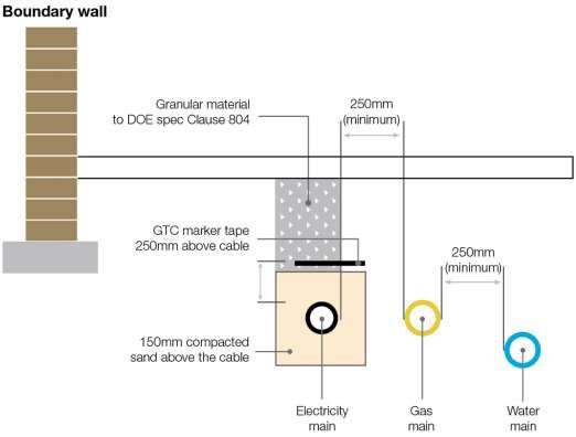
Section Six – Electricity Mains 15GTC Technical Guidelines
Figure 3 – Typical road section to show relative positions of utility apparatus
It is imperative that the electricity cables are not damaged following installation, and it is the responsibility of the
Developer to ensure that ALL persons working on-site are informed of the location of the electricity cables.
The mains and services drawings should be on site at all times and updated to clearly show the installation
progress. GTC will ensure that updates to the drawings are provided for your records.
Please note that other DNOs may have electricity cables in the vicinity of the site. They should be contacted by the
Developer at an early stage in order to establish the location of any non GTC mains that may be affected.
Damage to GTC’s electricity cables must be reported immediately to the GTC Electricity Emergency Number
0800 0326990 who will arrange for the Emergency Service Provider to attend site and undertake any repairs.
For further information refer to HSE publication HSG47 “Avoiding Danger from Underground Services” which gives
detailed guidance on avoiding damage to electricity mains and services, including information on detecting
underground services and safe digging practices.
Free information is available from the HSE Infoline on 0845 345 0055 or the HSE website www.hse.gov.uk.
Offsite Connections
GTC, or its appointed sub-contractor, will complete the offsite connection; this will include all necessary liaisons
with the DNO and highway authorities.
Section Six – Electricity Mains 16GTC Technical Guidelines Excavations The minimum depth of cover for LV mains should be 450mm / 600mm in footways / verges and 600mm in roadways from the finished ground level, as shown in Figures 1-3. The minimum depth of cover for HV mains should be 600mm / 750mm in footways / verges and 750mm in roadways from the finished ground level as shown in Figures 1-3. Cable should be installed in line with the trench layouts for the site, as agreed at the design stage. The bottom of the trench should be levelled to enable the cables to be bedded evenly and consistently throughout the trench, at the correct cover. Sharp stones must be excluded from the base of the trench. Where the base of the trench is unsuitable e.g. rocks and stones, the trench should be excavated a further 75mm in depth and this space should be filled with fine material e.g. sand or stone dust to lay the new cable on. No other utility mains should be installed over, below, or within 250mm to the side of the electricity cable. Road Crossing Ducts Any cable installed across the road will be in black 150mm OD (Outside Diameter) Class 2 ‘rigiduct’ plastic ducting compliant with the ENA TS 12-24. Ducts must be black on both internal and external faces. The ducting is available at most builders’ merchants. GTC can offer advice on the procurement of this material, if required. Where ducting is to be adopted by a DNO, their specification will be required and can be provided separately. Backfill Materials The Developer must ensure that the electricity cables are surrounded by fine material e.g. sand or stone dust. This will be built up to 150mm above the mains cable and laid immediately after installation to avoid damage to the cable. All cables must be backfilled to at least 250mm above the cable before they will be energised. All backfill and sub-base materials must be free from any organic, perishable or hazardous material. An ‘electricity’ marker tape or tile, supplied as free issue from GTC, must be incorporated within the backfill for all mains and road crossing ducts and be positioned 250mm above the cable. Note: Where cables are installed on behalf of a DNO the marker or tile tape requirements will differ. Section Six – Electricity Mains 17
GTC Technical Guidelines

                  Figure 4 – Cable sand surround and marker taping specifications

GTC will work with the Developer to ensure that the cable sand surround and marker taping is installed to our
specifications.

Section Six – Electricity Mains                                                                                 18
GTC Technical Guidelines Section Seven Electricity Services This section applies to domestic properties supplied via individual services. General Requirements All service terminations where possible should be located in external meter boxes and must be easily accessible to allow the meters to be read, maintained and isolated when necessary. No other equipment should be installed in this external meter box. Service terminations and meters must not be exposed to extreme temperatures, excessive humidity, vibration, corrosive substances or accidental damage. It is the Developer’s responsibility to identify and show the required meter positions on the site plans and liaise with GTC as early as possible. Services and cut outs will only be installed in substantially completed properties normally within 5 working days of a request. The service position must be safe and secure at all times, with meter boxes securely screwed to the wall and the doors fitted. When booking work, the Developer is required to confirm the GTC network and plot number. It is preferred that a minimum of three services, are booked and connected on each visit. Meter tails should ideally be installed into the meter box prior to GTC arriving on site to install the cut out, to aid the Developers electrician with the install of downstream cables and equipment and to eliminate the risk of the meter box being moved with a live service within. Meters will be installed by the Developer’s chosen supplier following connection of the electrical service by GTC and will need to be arranged separately with your nominated supplier. Externally Situated Meter Positions Ideally, service termination equipment and the meter should be located in an approved built-in meter box, on the wall closest to the electricity main at the front of the property. By prior agreement service termination equipment and the meter can be installed in garages or inside the building see Exceptional Circumstances section below for details. The fitting of external meter boxes and the installation of externally fitted hockey sticks is the responsibility of the Developer and must comply with the manufacturer’s specifications and comply with GTC’s requirements. The external meter boxes ‘hockey stick’ should be cleated to the wall using a suitable fixing. Section Seven – Electricity Services 19
GTC Technical Guidelines
Slim-line meter cabinets are not recommended due to the limited space available and requirements for smart meter
functionality that may require additional space in the future. The following installation procedure should be followed;
• Install the external meter cabinet (supplied by GTC, subject to contract) and ensure cabinet doors are
securely fitted.
• Install white ‘hockey sticks’ (supplied by GTC, subject to contract) between the end of the 38mm OD
‘polyduct’ service duct and the meter cabinet. The hockey stick should be supported while back-filling the
service route in order to ensure it remains perpendicular and ideally permanently cleated.
• All electricity service cables must be ducted from the meter position to the connection point on the mains
cable in the footway using 38mm OD (32mm ID) continuous black polyduct, conforming to ENA TS 12-24.
Ducting is supplied by the Developer and must be installed at a minimum depth of 450mm. It is important
to install the duct on a route exactly as shown in the design. Only one service cable is permitted in any
one service duct. The line of the duct must be a minimum of 250mm away from other utilities, such as the
gas service pipe or duct.
• Lay ‘Electricity’ marker tape, supplied by GTC, 250mm above the ducts before backfilling the trench.
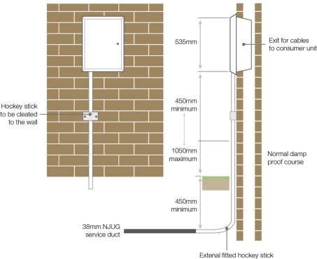
Figure 5 – Example of an externally situated meter position
Table 1 – Meter box and brickwork opening dimensions
Box Dimensions Brickwork Opening
Width 409mm Width 365mm
Depth 210mm Depth 150mm
Height 595mm Height 535mm
Section Seven – Electricity Services 20GTC Technical Guidelines
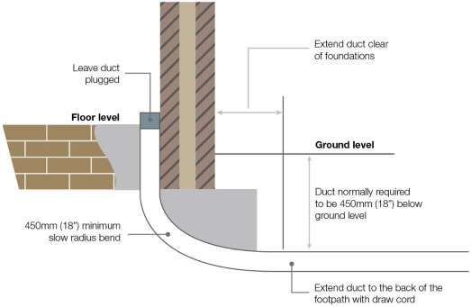
Below Ground
The ends of the duct must be capped or plugged at all times to prevent ingress of water or debris. The service duct
must be continuous between the meter position and the rear edge of the proposed footpath / service verge.
Figure 6 – Connection of meter to NJUG service duct
Exceptional Circumstances
Cavity Hockey Sticks – External Meter Boxes Single Phase Connections
Where it is not possible to install the hockey stick externally due to the outer finish of the property, then subject to
meeting the following conditions, a cavity installation may be approved.
• The meter box is installed in a location where access to the wall immediately behind the meter box and
hockey stick is not possible.
• Where access to the wall behind the meter box and hockey stick is possible, the Developer shall pre-install
a steel sheet of at least 1mm thickness to the wall behind the meter box to a minimum height of 1m from
floor level and the full width of the meter box. This is to prevent any possibility of drilling into the hockey
stick from within the property. This steel sheet shall be earth bonded as per current edition of
BS7671 Requirements for Electrical Installations.
These requirements shall be met prior to the connection and energisation of the service to the property.
Section Seven – Electricity Services 21GTC Technical Guidelines
Garage Meter Positions
Where the meter position is within a garage, although not deemed internal to the property, it is permissible
subject to:
• The service shall be protected by a suitable cable guard, provided by the Developer, for the full length from
the floor to the service termination position.
• The service position should be installed between 1.2m and 1.5m height to improve visibility and reduce the
risk of impact damage to the meter position.
• The service should be positioned at least 1.2m into the garage to reduce weathering damage.
• Where an increased risk of drilling into the service cable exists, the Developer shall pre-install a steel sheet
of at least 1mm thickness to the wall behind the service cable, service termination and meter. This SHALL
be connected to the main earth terminal by the electrical contractor.
Internally Situated Meter Positions
In premises where it is not possible to install external meter boxes i.e. listed buildings, properties situated in
conservation areas, where the Local Planning Authority will not allow an external meter box to be installed and
other agreed installations. Then, subject to satisfying all of the following conditions and at no cost to GTC, an
internal meter installation will be permitted:
• The service cable shall be installed in continuous black polyduct ducting of 38mm OD minimum (32mm ID),
conforming to ENA TS 12-24 which terminates at the level at which it enters the building. It shall be routed
inside the building by the shortest and most direct route possible to allow installation and/or future removal
of service cable as may be required. The internal end of the duct shall be sealed immediately after the
service cable has been installed.
Figure 7 – Installation of polyduct ducting on an internally situated meter position
Section Seven – Electricity Services 22GTC Technical Guidelines
• The incoming service cable must not be hidden by panelling of any type or be routed behind any fixture or
fitting.
• GTC’s service equipment should be installed on a brick or block-work wall and where possible, this should
be an external wall.
• In timber-framed buildings, and/or where an increased risk of drilling into the service cable exists, the
Developer shall pre-install a steel sheet of at least 1mm thickness to the wall behind the service cable,
service termination and meter. This SHALL be connected to the main earth terminal by the electrical
contractor.
• The following space is required: 1250mm high x 550mm wide x 300mm deep.
• The position must be a maximum height of 900mm from ground floor level to the bottom of the meter board
and a minimum height of 600mm.
• There is 750mm clear access to the front of the enclosure surrounding the service termination and
metering equipment.
Where it is proposed to install the service termination either under stairs or within the primary access/egress route
within the property, the following requirements shall also be met as an absolute minimum. Failure to meet these
requirements will result in the service to the property not being installed:
• As currently required by the Building Regulations Fire Safety Approved Document B Volume 1
Dwelling Houses, Section 2 Means of Escape where it is proposed to install the electrical service
termination under stairs or within an area regarded as primary access/egress route, then this shall be
regarded as a “Protected Area” and as such, shall be constructed in such a way as to provide a minimum
of 30 minutes fire protection.
• The door(s) providing access to the under stairs location and or cupboard housing the service termination
equipment shall be a rated “Fire Door” as determined in the regulations in “Appendix B Fire Doors” and
shall comply with the requirements of BS 476-22:1987, be a minimum of 44mm in thickness and of a
certified FD30 type, therefore providing a minimum fire resistance of 30 minutes. Although not an absolute
requirement, a fire door which prevents the spread of “Cold Smoke” and “Fire” by use of suitable seals and
one which is compliant with BS EN 1634-1 or BS 476 Part 22, is preferred.
• Immediately adjacent to the means of access to the under stairs location and or cupboard housing the
service termination equipment and in line with the regulations in Section 1 Fire Detection and Fire Alarm
Systems a linked fire detector shall be installed which as a minimum is to BS 5839-6:2004 with Grade D
Category LD3 Standard or better. Although not an absolute requirement, a mains-powered combined heat
and smoke detector compliant to BS EN 14604:2005, is preferred.
NB – Standard fibre-glass outdoor meter boxes are not suitable for use indoors as they do not comply with the
appropriate British Standards for Fire Resistance and Fume Emissions. It is the Developer’s responsibility to
ensure that any internal enclosures comply fully with fire regulations and any local planning requirements.
Section Seven – Electricity Services 23GTC Technical Guidelines
Service termination equipment and meters cannot be installed:
• On partition walls made of plasterboard, drywall or other similar material (unless compliant with the
requirements as listed above).
• Immediately adjacent to other utility apparatus, a minimum of 250mm separation is required.
• A partition is required between electricity and any water, which should be capable of withstanding water
under pressure in the event of a fault.
• Adjacent to any localised heating source, such as an immersion tank, heating boiler, radiator etc., a
minimum of 250mm separation is required.
• Above internal or external doorways.
• Inside a bin, coal or refuse store.
• Basement or cellar.
• Toilet, kitchen or bathroom.
• In any location in breach of the current edition of BS7671 Requirements for Electrical Installations.
Modular Housing
For developments utilising modular housing construction, requirements should be discussed with GTC at the
earliest opportunity to determine any bespoke requirements.
Electric Vehicle Charger Points
Typically GTC will only provide one service (and MPAN) to each individual plot of land. EV chargers should be
connected to the customers side where possible. Multiple services will not be provided to a single building.
Where an EV charger is to be installed for a private remote section of land (e.g. a remote garage) an additional
service is permitted, although this will result in an additional MPAN being raised for the same address.
Where EV Chargers are to be connected using standalone services, earthing shall comply with the latest edition of
BS7671.
Three Phase Domestic Meters
Where there is a need for a three-phase domestic service solution, early engagement with GTC is recommended.
The position will need to be suitable for all equipment, which can be significant if the supplier requires a smart
metering solution, which would presently require the installation of three single phase meters.
Section Seven – Electricity Services 24GTC Technical Guidelines
Embedded Generation
Applications should be made to GTC via embedded.generation@gtc-uk.co.uk.
The following information will be required in order to process the application:
• Completed G98 or G99 application form as applicable, including all addresses, MPANs and loadings the
application relates to.
• Single line diagrams for the connection.
• Test certificate/ data sheet for the equipment being connected.
• Site plan with plots clearly marked.
• Letter of authority from landowner to applicant allowing applicant to act on their behalf.
For applications on multiple properties a plot schedule showing inverters being connected to each plot is required.
Temporary Builders Supplies (TBS)
Applications for TBS for the site should be made via UMSO@gtc-uk.co.uk.
The following information will be required to process the application:
• Load required (in kVA and including number of phases required).
• Location of where the connection is required.
• Completed GTC electric design for the site.
TBS supplies shall be installed onsite in a suitably sized, secure, lockable, waterproof, semi-permanent structure
(e.g. a GRP or brick-built kiosk).
TBS supplies shall be offered as TT earthing. If your site requires a supply with disturbing network characteristics,
for example a tower crane, early discussion with GTC is recommended.
Section Seven – Electricity Services 25GTC Technical Guidelines Section Eight Multiple Occupancy Buildings Early consultation with GTC should take place as there are a number of different approaches which can be employed. This guidance should be read in conjunction with ENA Engineering Recommendation G87 Guidelines for the Provision of Low Voltage Connections to Multiple Occupancy Buildings. The Developer is to provide a suitable secure and fireproof enclosure for service termination and distribution board (if required) in a suitable common access location on the ground floor, minimising route length to the exterior and which provides a suitable ducted cable route with access 24/7. Intake Position The preferred arrangement is for all electricity supply cables to enter the building at a single point, the intake plant room. The supply intake position (which may not be the metering position), should be a suitably sized, secure, ground floor plant room accessible from a communal area preferably adjacent to the entrance and as near as possible to the point of entry of the supply cables. Basement intake positions are not normally acceptable due to the risk of flooding. If, however, the design of the development necessitates an intake position below ground level, special consideration must be given to the likelihood of flooding and special measures such as pumping or flood walls must be considered where necessary and agreed in advance with GTC. Where more than one intake position is required early consultation with GTC should take place due to the increased risks associated with the supply and potential impact on the design of the wider cable network, specifically in relation to the earthing system for the site. Multi Service Distribution Boards (MSDBs) must be fitted within a secure, fire-rated cupboard (minimum of 30- minutes, or in-line with the building fire risk strategy). Section Eight – Multiple Occupancy Buildings 26
GTC Technical Guidelines

Meter Locations
GTC will assume all multi occupancy dwellings will have a mains cable terminated in a multiway cabinet and
meters terminated in or around the main entrance at ground floor level unless otherwise stated by the Developer.

Each meter position should be clearly labelled with the flat number.

The preferred location for meters within flatted properties is within a dedicated ground floor meter room alongside
the MSDB. Group meter positions are also acceptable on each floor, or various floors provided they comply with
our standards, are accessible and clearly marked on drawings.

The position and number of service positions shall depend on the distance from each flat such that the lateral
wiring can be installed within the design requirements of the current edition of BS7671 Requirements for Electrical
Installations.

In order of preference the number/position of services shall be:
    •    A single communal position for the MSDB, service terminations and meters on the ground floor.
    •    A communal position for the MSDB, service terminations and meters located on multiple floors.
    •    Service termination and meters located within individual properties, with risers and laterals through the
         building from a communal position either on the ground floor or multiple floors.

An enclosure door must be lockable and fire-rated to a minimum of 30-minutes, or in-line with the building fire risk
strategy. The communal position should not be situated in the primary means of escape from the building.

In all situations GTC will require 24-hour access to equipment used to provide supplies within multi occupancy
dwellings. This access is for the purposes of inspection, maintenance and repair as may be required and therefore
the Developer will be expected to provide keys and/or access codes for all common corridors, stairwells and utility
cupboards, unless secured by Fire Brigade FB1 or FB2 locks.

Cut outs should not be inverted under any circumstances to ensure consistency on expected live terminals.
Sufficient space should be allowed for service cable bending to standard orientation.

Distribution boards must be adequately fitted and secured to the wall prior to the cables being installed. While wall
requirements are site specific, typical MSDB weights can be provided on a site-specific basis referring to the
manufacturer’s data sheet. Typical installations will require the use of M10 type bolts. Wood screws are not
acceptable.

Section Eight – Multiple Occupancy Buildings                                                                         27
GTC Technical Guidelines
Group meter positions must:
• Be for electrical equipment only.
• Be of adequate size for the installation of cut outs, metering equipment and isolation equipment.
• Be formed in brick or blockwork only. Note: plasterboard partitions are not permitted.
• Have full width opening doors and space in front for access to equipment.
• Be fire resistant to comply with fire regulations.
• Not be used as a storage room.
• Not be under stairs where headroom is less than 1.5m, or in a room with less than 2.0m headroom.
• Top level of any meter shall not be more than 1.8m above floor level in accordance with MOCOPA
guidelines.
• Not be below ground level i.e. basements.
• Have ducted cable entry with easy bend to vertical position adjacent to wall. The ducts must be sealed
after the installation of the supply cables to prevent the ingress of gas.
• Have output routes for lateral services with supports provided at least every metre.
Although individual installations will vary with each building design, the following table provides guidance on the
minimum dimensions required to accommodate GTC’s equipment and associated metering.
Section Eight – Multiple Occupancy Buildings 28GTC Technical Guidelines
Figure 8 – MSDB location
Table 2 – Size guide for MSDBs, allowing for opening of doors
Flats Width Height Depth
Up to 12 846 1000 450
Up to 15 893 1000 450
Up to 18 938 1000 450
Up to 24 1032 1000 450
Up to 30 1125 1000 450
Up to 36 1217 1000 450
Up to 45 1150* 1000 450
Refer to manufacturer data for site specific requirements if needed. *Does not allow for a J2 option.
Individual meters within flats
Meter positions within flats must comply with the Exceptional Circumstances section of this document for internal
services.
Section Eight – Multiple Occupancy Buildings 29GTC Technical Guidelines
Risers and Laterals
Where meters are not located at the intake positions, risers will be required to supply each floor, with laterals
required for any meter locations a distance from the riser.
All cables installed for risers and laterals will be Low Smoke Zero Halogen (LS0H).
The Developer shall provide and install lateral wiring to each flat complying with the current edition of BS7671
‘Requirements for Electrical Installations’.
When installing Risers and Laterals the Developer must:
• Provide a suitable safe access platform for installation of all cable riser works, where required for GTC
installation.
• Ensure that the electricity riser entry points into the building and through floors on flatted properties, have
been suitably drilled and sleeved without the need for off setting the cable work, where required.
• Ensure that the riser and sleeve which pass through each floor on flatted properties are fire stopped in
accordance with building regulations, where required.
In situations where GTC has agreed to adopt riser and/or lateral cables, the Developer’s electrical contractor may
agree to complete the installation in accordance with the following requirements:
• The electrical contractor will install riser and/or lateral cable forming part of GTC’s distribution network in
accordance with BS7671 Requirements for Electrical Installations.
• Will be required to submit a completion certificate for any and all riser and/or lateral cables, prior to
energisation.
Failure to comply with these requirements may prevent connection of the equipment.
Where the Developer is to install adoptable riser and/or lateral cables on behalf of GTC, GTC will provide LS0H
cabling free issue, as detailed in the accepted quotation.
GTC require 24/7 access to all of our equipment, including cabling where GTC has agreed to adopt riser and/or
lateral cable, and therefore suitable cable access positions should be provided. If the Developer wishes GTC to
consider other options, then early discussions are recommended. The Developer will be responsible for any fire
blocking / barriers between floors.
Secondary Supplies
Where the need for an additional supply to a building is identified, which falls into the category of “firefighting and
other standby supplies” as is defined within the Energy Networks Association (ENA) document G87 Guidelines for
the Provision of Low Voltage Connections to Multiple Occupancy Buildings, the requirement will be dealt with on a
site by site basis and in strict accordance with the ENA guidelines. In all cases the recommendation is for standby
generation to be used.
Building Network Operators (BNOs)
Under some circumstances, particularly for large multi-occupancy buildings, the network downstream of the intake
position could be owned, operated and maintained by the building owner. In this case GTC will be responsible for
the network up to the first point of isolation at the intake position with the building owner responsible beyond this.
A site responsibility schedule will be fitted at the boundary location. A Point of Isolation shall be installed
immediately after the GTC cut out to allow for isolation of BNO network without GTC attendance.
Section Eight – Multiple Occupancy Buildings 30GTC Technical Guidelines Section Nine Non-Domestic Properties – Meter Positions We recognise that space is always at a premium and will work with you to develop the most appropriate position that can be achieved with the least amount of space used. Early discussions will be required to ensure that the best solution is incorporated into your building design. For external meter positions, the Developer must provide a suitable kiosk (waterproof and lockable and of a semi- permanent nature i.e. GRP / Brick) and arrange metering with a supplier. For internal meter positions, the Developer must provide ducting of adequate size for the incoming cable, a dedicated meter room/cupboard for termination equipment and arrange metering with a supplier. GTC will endeavour to provide PME earthing where possible but some installations may necessitate SNE or TT earthing and early discussion with GTC is recommended. Section Nine – Non-Domestic Properties – Meter Positions 31
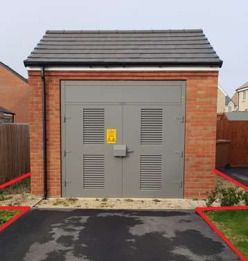
GTC Technical Guidelines

Section Ten
Substations
The Developer will carry out all civil work associated with installing substations. Substations will be built to GTC’s
specifications and drawings and all substation sites will be subject to a lease or land purchase. The Developer is
required to obtain planning permission and building regulations compliance for these structures.

For most sites, a choice of GRP building or brick-built substations with GRP or steel doors is offered. However,
where proximity to buildings is an issue, or where the need for higher levels of security is identified, GTC reserves
the right to specify the type of substation and doors to be used. The Designer will complete a bespoke risk
assessment for each substation location.

Typically, a brick-built substation can be constructed with at least 3m clearance from the nearest property.
However, a GRP enclosure provides less noise attenuation and therefore requires a greater clearance from the
nearest property. These clearances vary depending on location and size of transformer to be installed within the
housing and will vary from 7m to 19m.

 Figure 9 – A typical brick-built substation with at least 3m clearance to nearest property

Section Ten – Substations                                                                                           32
GTC Technical Guidelines

The red lines on Figure 9 represent the extent of GTC’s required access for either a brick substation or GRP
enclosure, which is typically 1.5m from the area subject to land transfer. This requirement covers both sides and
rear of the substation. The requirement for the front of the substation will be dependent upon its specific location.
However, where the substation opens onto a footpath, a minimum of 1.5m from the back edge of the footpath is
required; this is to enable the substation doors to open without encroaching into the footpath.

In order to establish a substation, GTC will, in most instances, look to acquire an area of land 4.24m x 4.24m to
cover the substation base, with a 1m easement containing restrictions within a 0.5m proximity of the easement.
Alternative substation and easement sizes may apply and should be discussed with the GTC Designer at the
earliest opportunity.

Bespoke solutions offered by the Developer may be considered but final approval remains with GTC.

In order to maintain our substations, GTC requires suitable and unrestricted 24-hour access for HIAB crane
vehicles to all sites, to enable installation and/or recovery of electrical plant.

In some instances, the substation will require a Segregated (“HOT”) earthing system to be installed in order to
manage Earth Potential Rise voltages on the network. This will result in restrictions imposed on installing any
supplies and/or metal street furniture (including streetlights) within 10m of the substation. Typically, this will be seen
in rural areas where large parts of the electric network are supplied via overhead lines, however early discussion
with the Designer is recommended to confirm.

Section Ten – Substations                                                                                             33
GTC Technical Guidelines

Section Eleven
Installing Meters and MPAN Issue
The Developer must liaise with their chosen electricity supplier to install meters.

MPAN Registration
GTC have developed the following guidance to make the new connections process as clear and simple as
possible.

Plot to Postal Address
Plot to postal address issues has long been identified in causing confusion within the new connections arena.

                            Figure 10 – Postal address application process

As shown above, the confirmation of address data has several approval points. There are no defined timescales
for approval by the local authorities. Royal Mail also retains the right to veto address applications until it issues
postcodes. For these reasons Developers are advised to begin the address application process as soon as
possible following planning approval to allow sufficient time for processing.

The guideline from local authorities and Royal Mail is approximately 12 weeks.

MPAN Allocation
It is GTC’s preference to issue MPANs upon confirmation of the postal address and postcode from the Developer.
This is recognised standard practice in several DNO areas and is effective in minimising the data issues in
changing from plot to postal address. GTC recognises that in all cases this is not always possible and will work
flexibly to help Developers. On large developments, MPANs shall be allocated in a phased manner to enable
better data quality as plans come to fruition. The Developer should ensure that the plot to postal information
provided is accurate in order to aid correct MPAN allocation.

Section Eleven – Installing Meters and MPAN Issue                                                                       34
GTC Technical Guidelines
Installation and Crossed Meters
The potential for crossed meters (meter information allocated to the wrong postal address) is a particular problem
in the industry, especially for high density developments (flats). To minimise the potential for errors the following
system is recommended.
Contractors and M&E fitters should implement a tagging system when fitting out the flats. By tagging the tails to
each flat with the Plot/Postal address PRIOR to pulling them through to the meter board. This will clearly identify
which flat the tails are linked to.
Tagging the Meter Board
Meter boards may be in communal positions held in basements or on each floor. Clearly labelling the meter boards
with the Plot/Address/MPAN where the meter is fitted will assist the Meter Operator (MOP) in completing their job.
Having the boards and tails clearly tagged will minimise the room for error during meter fit.
• The issuing of post code and postal address can take up to 12 weeks.
• Ensuring that meter information is not ‘crossed’ will help to reduce the safety risk to customers, customer
dissatisfaction, incorrect billing and the subsequent problems for suppliers and customers.
• Good communication with GTC will help provide better customer service.
Unmetered Supplies
In addition to your accepted GTC quotation, GTC also requires an Unmetered Supplies Agreement where there are
unmetered connections (e.g. street lighting, traffic signals) onto our electrical network.
In the majority of cases the connections will be on adoptable land where the local authority will ultimately take
ownership of these connections when it adopts the highway. During the build stage the Developer will be
responsible for the payment of the energy consumption for these columns. Where the columns are on private land,
GTC will require an Unmetered Supply Agreement between the Management Company and GTC.
Ducts for adoptable streetlights shall be black, in line with Local Authority requirements. Orange ducts are
permissible for private cables only.
To ensure GTC can carry out these connections we require the following documentation to be in place:
• Developer to issue a council approved drawing, which enables GTC to do the following:
o Design.
o Quote.
o Calculate the annual consumption of the connections in accordance with the Elexon procedure
BSCP520.
• Developer’s acceptance and payment of the quotation.
• Signed copies of the Unmetered Supplies Agreement and the Letter of Intent Authorisation received.
Where supplies are required for traffic signs, bollards, traffic lights, street lighting columns sited on roundabouts or
similar situations, GTC will provide a service into a supply pillar provided by the Developer from which private
cables will supply the particular installation. Normally such installations will be metered.
Section Eleven – Installing Meters and MPAN Issue 35Head Office Synergy House Woolpit Business Park Woolpit Bury St Edmunds Suffolk IP30 9UP T: 01359 240363 E: info@gtc-uk.co.uk W: www.gtc-uk.co.uk
You can also read