HOT CARGO SUPPORT AND INSULATION PADS INSTALLATION MANUAL - FEROFORM F3637
←
→
Page content transcription
If your browser does not render page correctly, please read the page content below

FEROFORM F3637
HOT CARGO SUPPORT AND INSULATION PADS
         INSTALLATION MANUAL
Introduction

The FEROFORM hot Tank Support Pad system from TENMAT is a versatile and
very simple support system for hot steel tanks (containing Sulphur/Bitumen/Asphalt/
Coal tar). The system is very easy to adjust to ensure that sufficient surface contact
is achieved between the base of the tank and the pad giving optimum support and
insulation.

The following manual describes the general instructions for installation of
FEROFORM F3637 in both:

      A. Vertical load supports (Typically 3 different options)

          i) Ships Rib

          ii) Support pillar

          iii) No penetration

      B. Side load supports (anti-pitch and anti-roll)

These instructions are based on installation procedures for the basic design of the
supports (please refer to the typical drawings of vertical and anti-pitch/anti-roll
supports).

For the vertical load supports the basic installation is common to all 3 designs. Any
variations in the individual installation procedure is highlighted.

Because the TENMAT FEROFORM F3637 system is very versatile, on occasions
shipyards and designers prefer a slightly different design for their supports, but in
these cases the principle procedure remains the same for installation and we are on
hand to guide you where necessary.

In general, we recommend positioning the support points where possible at the
intersection between the longitudinal girders and the web frame ribs (Option Ai), in
this way avoiding unnecessary extra structural support.
Preparation

     1) The base plate should be cut, drilled and the chocking dam welded in place
        prior to welding to the support structure. (Note that the jacking screw holes
        may be either tapped in the plate or use nuts welded to the underside of the
        plate and the dam plate needs only to be 3 mm steel as its only purpose is
        to retain the chocking compound until it is fully cured).

     2) The support plate should have Ø6mm weld beads spaced 25 mm apart at
        right angles to the direction of expansion of the tank, this is required to
        maximize the chock bond and thus the shear strength between the chock
        and the steel plate. The exact pattern of the weld bead is unimportant.
        Lines, squares, zig-zag, spots etc are all acceptable.

Assembly

     1) Fit the leveling screws, FEROFORM pad and security bolts (do not tighten
        the security bolts at this stage). The optimum thickness of chock for the
        Tenmat system is 20mm thick between the FEROFORM plate and the base
        plate. To start at this optimum chock thickness the jacking screws should be
        fitted to protrude 20mm above the support plate.

     2) Fit the anti-pitch and anti-roll pads before the tank is lowered (see section
        B)

     3) The tank can now be lowered into its final position and it will need to be
        supported until the next stage is completed, (at this stage be careful not to
        damage the Anti Roll / Anti Pitch pads). Ideally hydraulic jacks are
        recommended as they allow easy adjustment of the tank. Note grease may
        be applied to the counter face if so desired as an anti-corrosion measure
        but this is not essential as FEROFORM pads are non-corrosive and also
        have a mild cleaning action that will help minimize counter face corrosion.

     4) The depth of the counter bore in the pad is chosen to create a 5mm gap
        between the head of the security bolt and the base of the tank. If required,
        the bolt head thickness can be reduced to achieve this clearance.

     5) A plug (PTFE is suggested) can be used to provide further insulation on top
        of the bolt if desired.
Installation

      1) The chock thickness is to be between 15mm and 25mm. Adjustment of the
         tank should be made if needed to achieve this. Extra counter face plates
         can be welded in place for those supports that exceed 25mm thickness of
         chock. It is not essential that all supports have identical chock thickness.

      2) Level the pad to the bottom of the tank using the leveling screws to get a
         good contact surface area. This can be checked with a 0.25mm feeler
         gauge around all 4 sides of the pad. The pad only needs 35% contact to
         meet the required specifications however it is advisable to get as much
         contact area as possible. Normally 75% to 85% contact can be easily
         achieved. The adjusting screws do not need locking in place but may be
         tack welded if desired.

      3) Then inject the chocking compound into the dam area according to the
         manufacturer’s instructions and procedures until it overflows the dam plate.
         Once the chocking compound is fully cured the tank supports may be
         removed. At this stage the security bolts may be tightened. Finger tighten
         ONLY and tack weld the nuts to prevent loosening. If preferred locknuts
         can be used. It is important that the security bolts are not over tightened as
         this would lead to the FEROFORM pad being distorted thus compromising
         the effectiveness of the system.

Where “no penetration” is possible i.e. double hull designs or where the advantage
of the alignment feature of the FEROFORM F3637 tank support pad is not chosen, a
simple flat system may be used to accommodate the use of FEROFORM F3637. In
general, follow the installation procedure for (i and ii above) with the following
modifications.

Due to the need to adjust the jacking screws the damplate should only be fitted after
installation and levelling. The dam plate can be tack welded in place and sealed with
silicone sealant prior to chocking. The tank should be raised prior to chocking to
allow the security bolts to be finger tightened ONLY on to the F3637 pad.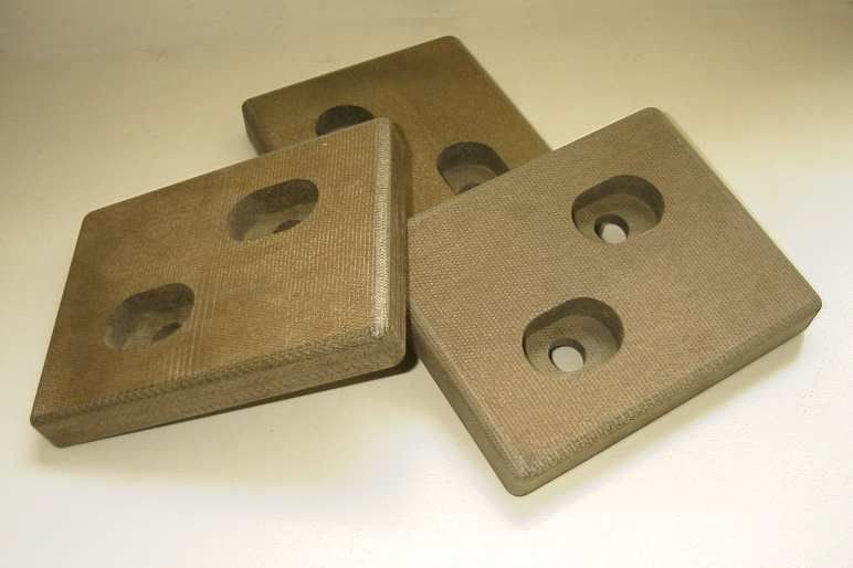
This gap size is to
            25 mm
                              allow for chocking

                                                    Security bolt

Dam plate
                                                      F3637 Pad                          Chock

                                                                                             32.5 mm
    20±5 mm

                                                                    M10 jacking screws

                    Finger tighten nut
                    & tack weld
                                                            This surface to have
                                                            Ø6mm weld beads 25mm
                                                            apart prior to chocking
Introduction

Side support Anti Roll pads are normally mounted along the centerline of the tank
and the Anti Pitch pads at the pump house end of the tank. The function of these
pads is to absorb the pitch and roll forces and control the expansion / contraction of
the tank. These pads are 5mm thicker than the vertical support pads to provide ex-
tra insulation. They are retained by bolts and the gap to the tank adjusted by the
use of shims fitted between the pad and its support.

Preparation

The anti pitch / anti roll structures should be completely fabricated including the ap-
propriate holes. Since chock is not required for anti pitch / anti roll pads then dam
plates are not used.

Installation

   1) Fit the anti pitch / anti roll pads in place with the appropriate bolts. At this
      stage the bolts should be only lightly tightened.

   2) The tank should now be installed according to the instructions given in sec-
      tion A) for the vertical pads.

   3) The anti pitch and anti roll gaps between the FEROFORM pads and the
      tanks should now be measured and suitable steel shims produced to reduce
      the gap to approx. 1-2mm. These shims are fitted by loosening the retaining
      bolts and sliding the shims between the support structure and the back face
      of the FEROFORM pads.

   4) Once in place the retaining bolts can be tightened and the nuts must be tack
      welded to prevent loosening. If preferred locknuts can be used.
Please complete and return this page to confirm your having read and understood and followed the installation instructions. I confirm that I have read, understood and followed all of the fitting instructions and that FEROFORM F3637 Load Bearing Insulation System has been installed according to these instructions. Project / Shipyard / Vessel Hull Number Company Print Name Position Signed Dated TENMAT and its agents cannot be held responsible for any damages, loss of earnings or additional costs incurred due to failure to comply with the installation instructions and in this case all warranties will be null and void.
FEROFORM                                  FEROGLIDE

              REFRAVER                           REFEL                     ARCLEX
                                          NITRASIL                         SINDANYO

               TENMAT is committed to the highest standards in customer service and
               our international staff is looking forward to assist you.

               CORPORATE HQ               NORTH AMERICA                SCANDINAVIA
               TENMAT Ltd.                TENMAT Inc.                  TENMAT
               Ashburton Rd West
               Trafford Park              23 Copper Drive              Stureplan 13
               Manchester M17 1TD         Newport, DE 19804            111 45 Stockholm
               England                    USA                          Sweden
               Tel.: +44(0)161 872 2181   Tel.: +1 302-633-6600        Tel: +46 (0) 8 612 68 50
               Fax: +44(0)161 872 7596    Fax: +1 302-633-6838         Fax: +44 (0) 161 872 7596
               Email: marine@tenmat.com   Email: info@tenmatus.com     Email: marine@tenmat.com
               Web: www.tenmat.com        Web: www.tenmatus.com        Web: www.tenmat.com

               Visit us on the web at www.TENMAT-MARINE.com
               ITALY                      FRANCE                       GERMANY
               TENMAT                     TENMAT                       TENMAT

               Via Dante, 2/48            56 Avenue Foch
               16121 Genova               77370 Nangis
               Italy                      France
               Tel.: +39 (0) 10 5451343   Tel.: +33 (0) 1 60 585656    Tel.: +49 (0) 7151 1338468
               Fax: +39 (0) 10 5760553    Fax: +33 (0) 1 64 083617     Fax: +44 (0) 161 872 7596
               Email: info@tenmat.it      Email: info@tenmat.fr        Email: info@tenmat.de
               Web: www.tenmat.it         Web: www.tenmat.fr           Web: www.tenmat.de

iss. 08/17                                                                                         Part of
You can also read