Installation Instructions For Audi TT* and Volkswagen Mark IV* chassis including: Jetta 1.8T (2000-01) Jetta VR6 (1999-01) New Beetle 1.8T ...
←
→
Page content transcription
If your browser does not render page correctly, please read the page content below
Installation Instructions
           For Audi TT*
                and
      Volkswagen Mark IV*
        chassis including:
       Jetta 1.8T (2000-01)
       Jetta VR6 (1999-01)
    New Beetle 1.8T (1999-01)
    Golf 1.8T & VR6 (2000-01)

        Front Big Brake Upgrade

                 *For kit Number 83-100-4300 & 83-886-4300

98.100.1430.09                                               Rev.H 11-05-07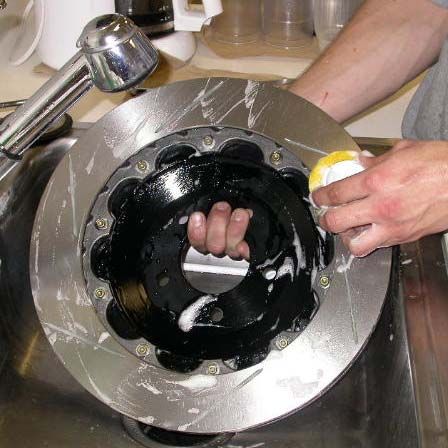
Note -

These instructions are for the Audi TT and Volkswagen Mark IV chassis ve-
hicles. The photos shown are of an Audi TT. The Volkswagen applications
use the same caliper brackets, rotors and hats, and the caliper bodies are iden-
tical, so the installations are very similar on all vehicles.

The one main difference is the brake lines, which may vary slightly from
the photos shown. Also, brake pad wear sensors and ABS line routing
may vary. Though the actual fitment may look slightly different, the order
in which the kit is installed is the same for all vehicles.

If you have any questions, please contact the StopTech Customer Service
Department at 310-218-1091.

Our Technical Support direct e-mail is: support@stoptech.com

                           www.stoptech.com                                2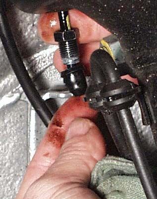
APPLICATION DISCL
                         APPLICATION       AIMER
                                     DISCLAIMER

Caliper Clearance
Most 17” wheels will clear the outer diameter of the caliper for a 328mm or 332mm rotor kit. For a
355mm kit, a minimum 18” wheel is typically required, and for a 380mm rotor kit, a minimum 19”
wheel is needed. The more critical clearance, however, is the gap between the spokes of the wheel
and the face of the caliper. Do not assume that a larger-diameter wheel will automatically clear the
face of the caliper.

To determine the actual metal-to-metal distance from the stock rotor face to the inside of the wheel
spokes, refer to the StopTech website at www  .stoptech.com
                                         www.stoptech.com
                                              .stoptech.com, and click on the ‘Wheel Fitment Charts’
link at the bottom of the home page. BEFORE printing out a copy of the wheel fitment drawing for
your vehicle, click on the ‘How do I use the charts?’ link at the top of the page, and review the
instructions carefully, to ensure that you have a full understanding of how to accurately measure the
critical wheel clearances. Only then should you click on the link for your vehicle, and print out the
appropriate wheel fitment drawing, to use as a measurement template.

It is very important that you verify the accuracy of the scale of the printout by matching both a
width and length dimension on your vehicle. Dimensions are shown in millimeters, but one di-
mension in each direction is also shown in inches, and StopTech recommends adding at least 2mm
of additional clearance to these dimensions. Follow the instructions carefully, to produce a fitment
template, and take care to ensure that your measurements are very precise.

Note: Final fitment of the wheel to the caliper is the rresponsibility
      Final                                              esponsibility of the customer
                                                                              customer..

Wheel Spacers
Wheel spacers can provide extra clearance to the outer face of the caliper. This will also space out the
entire wheel, widening the track width of the vehicle. Fender clearances should be checked on
lowered cars, and longer lug studs or wheel bolts are usually required.

Note: The Wheel Industry Council has issued guidelines advising that wheel spacers not be
used. It is the responsibility of the customer to ensure that wheel spacers are properly
specified and installed.

Caliper
 aliper,, Hat and B
          Hat      racket F
                  Bracket  inish D
                          Finish  isclaimer
                                 Disclaimer
Many wheel-cleaning solutions contain strong acids that may damage the finish on any caliper or
aluminum anodized finish, especially the plating on the hardware. Check for adverse effects by
trying a small amount of the cleaner in question on an inconspicuous area. Avoid over-spraying,
and rinse cleaning solutions off as quickly as possible. StopTech is not liable for damage to calipers,
hats or bracket finishes, due to corrosive chemical exposure.

                                   www.stoptech.com                                             3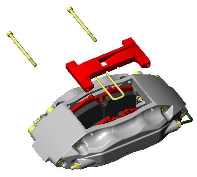
APPLICATION DISCL
                APPLICATION       AIMER (Cont
                            DISCLAIMER  (Cont’’d.)

Permanent Trimming of D
 ermanent              ust SShield
                      Dust   hield
The dust shield on each front wheel must be permanently trimmed, to accommodate the AeroRotors.
This involves cutting each shield with sheet metal snips or a power cutoff wheel, and deburring
sharp edges with a file or power die grinder. These operations can be dangerous, and serious injury
can occur. For anyone who is not competent or comfortable performing these operations, StopTech
firmly recommends seeking the services of a trained professional. Proper precautions, such as
safety glasses and work gloves, will be required.

Brake Noise
      Noise
Certain brake pad compounds make more noise than others. Proper anti-squeal shim plates be-
tween the caliper pistons and backing plate of the pad help to reduce the problem. Anti-squeal
lubricants are also available, to reduce some of the noise. The reality is that performance pads are
more prone to brake squeal.

Note: The customer is responsible for any squeal-related problems due to pad selection.

Brake Vibration - THIS IS IMPORTANT!
                          IMPORT
The most common cause of brake vibration is improper bed-in of pads and rotors, or improper pad
selection for the specific driving environment. Rotor run-out may also cause vibration, but preci-
sion manufacturing and inspection typically mean that run-out is not an issue. Modern produc-
tion methods ensure that the rotor run-out is within +/- 0.002” when installed on a StopTech alumi-
num hat, and it controls thickness variation to within 0.0003”. Under the most extreme conditions,
any rotor may warp, but uneven pad deposition is a more typical cause of vibration. If the system
is not properly bedded-in, or if street pads are run on an open track, uneven pad deposits will occur,
causing an ever-worsening vibration. Failure to immediately address a pad deposition/vibration
issue may lead to permanent damage of the rotors. Please read and understand the bed-in proce-
dure included in this manual.

Note: StopT
      StopTech is not liable for vibr
       topTech                       ations caused by eextr
                                 vibrations             xtreme usage or impr
                                                        xtreme              oper bed-in of
                                                                        improper
pads and rotors.

StopT ech, SSpor
 topTech,    por tS
             portS top, B
                 tStop,  alanced B
                        Balanced  rake U
                                 Brake  pgrades and A
                                       Upgrades      er
                                                    Aer oR
                                                      eroRotor ar
                                                        oRotor aree trademarks of SStopT
                                                                    trademarks      topTech.
                                                                                    topTech.
All other company or brand names mentioned or shown in this manual are trademarks of
their respective companies.

                                   www.stoptech.com                                           4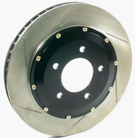
Impor tant N
                                     mportant   otices
                                               Notices
Wheel Fitment
Do not assume that your wheels will fit. An outline drawing of your StopTech Big Brake kit is
available on our website at www   .stoptech.com
                             www.stoptech.com
                                  .stoptech.com. Measure the distance from the outer face of your
stock caliper to the inner face of your wheel spokes, or make a template according to the instruc-
tions on the website, to determine if a wheel spacer is necessary. DO THIS BEFORE YOU
INSTALL YOUR KIT!

Cleaning of Rotors
The AeroRotors supplied with this kit are coated with a water-soluble, environmentally friendly
rust inhibitor. This coating MUST BE WASHED OFF WITH SOAP AND WATER before installa-
tion. Brake cleaner is not as effective as soap and water. Even if it doesn’t look as if anything is
coming off the rotor, the rust inhibitor is there, and must be entirely cleaned. Rotors will quickly
rust without protection, so if the rotor is not rusty, it’s still coated. After cleaning, you may see the
rotor start to develop a slight rust color. This is normal, and indicates that all of the rust inhibitor
has been removed.

Rotor and Pad Bed-in
          Pad
Proper rotor and pad bed-in is essential to the performance of your new brake system. Failure to
properly bed-in the brakes will seriously impact how well they work, and how long they will last.
The number one cause of brake vibration is uneven pad material deposition on the rotor. Proper
bed-in will greatly minimize such problems. Follow, as closely as possible, the bed-in procedure
detailed later in this manual, or refer to the StopTech website at www.stoptech.com for further
                                                                   www.stoptech.com
information.

Safety Notice
       Notice
Improper handling of a vehicle, especially while raised and supported by jack stands, ramps or
other mechanical means, can cause serious bodily injury or even death. It is strongly recommended
that a trained, experienced mechanic, with proper equipment, install the Big Brake Kit supplied by
StopTech. StopTech assumes no liability, expressed or implied, for the improper installation or use
of this product or its components.

                                    www.stoptech.com                                             5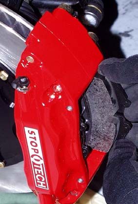
Impor tant N
                            mportant   otices (Cont
                                      Notices (Cont’’d.)
Disclaimer of Warranty / Limitation of Liability
By purchasing the STOPTECH brake components described herein and opening the accompanying
box or packaging, the purchaser(s), buyer(s) and /or the ultimate user(s) expressly (1) acknowledge
that they have read and understand all terms set forth herein; (2) understand and agree that the
STOPTECH brake kit and/or components, whether acquired new or used, whether complete or
incomplete, whether of merchantable or non-merchantable quality, whether saleable or non-saleable,
is taken, purchased, selected and/or acquired “AS IS” and “WITH ALL FAULTS”; (3) acknowledge
that the brake kit and/or components contained herein are intended only for off-street use, regardless
of whether said brake kit and/or components are approved by a state or the United States Department
of Transportation; (4) understand and agree that they bear all risks, including but not limited to the
risk as to quality and performance of said brake kit and/or components, and the risk of bearing the
costs of repair or replacement of the subject brake kit and/or components, whether in defective or
non-defective condition. STOPTECH is not responsible for damage, consequential or otherwise, for
equipment failure or mal-performance after installation: understand that (5) Auto Racing is a
dangerous sport, and products are subject to failure when exposed to the high stresses involved with
use on a racetrack.

        STOPTECH MAKES NO EXPRESS OR IMPLIED WARRANTIES, WHETHER ORAL
OR WRITTEN, WHETHER TRUE OR UNTRUE AND REGARDLESS OF SOURCE, TO ANY
PURCHASER(S), BUYER(S) OF ITS BRAKE KITS AND COMPONENTS. ANY IMPLIED
WARRANTY OF MERCHANTABILITY OR WARRANTY OF FITNESS FOR A PARTICULAR
PURPOSE IS HEREBY EXPRESSLY AND EFFECTIVELY DISCLAIMED AND SUCH
DISCLAIMER IS ALSO HEREBY ACKNOWLEDGED BY THE PURCHASER(S), BUYER(S)
AND/OR ULTIMATE USER(S). RATHER, THE PURCHASER(S), BUYER(S) AND/OR
ULTIMATE USER(S) EXPRESSLY AND IMPLIEDLY AFFIRM THAT HE/SHE/THEY ARE
RELYING UPON THEIR OWN SKILL AND JUDGMENT IN SELECTING AND PURCHASING
THE KIT AND/OR COMPONENTS CONTAINED HEREIN AS SUITABLE FOR THEIR
INTENDED USE. The purchaser(s), buyer(s) and/or the ultimate user(s) understand and agree that
no officer, director, employee, agent salesman, representative, distributor, or other affiliate of
STOPTECH has any authority to make nay statement or representation contrary to the terms set forth
hereinabove. Any such statement or representation is hereby effectively disavowed.

                                  www.stoptech.com                                            6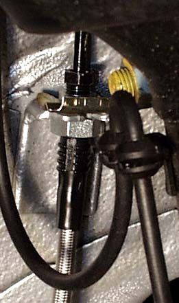
Audi TT & VW Mk IV Front Axle Kit
Safety Notice

Improper handling of a vehicle, especially while raised and supported by jack stands, ramps or other
mechanical means can cause serious bodily injury or even death. It is strongly recommended that a
trained, experienced technical mechanic, with proper equipment, install the Big Brake Kit as
supplied by STOPTECH LLC. STOPTECH LLC assumes no liability expressed or implied for the
improper installation or use of this product or its components.

Please read and understand this ENTIRE Installation Manual, including the
attached Break-in Procedures before starting the installation.

Tools and Equipment Required

18mm socket and ratchet (1/2” drive suggested), or wrench
17mm socket (1/2” drive suggested)
14mm wrench
11mm wrench
1/2” socket drive and ratchet (6 point suggested)
Torque wrenches capable 10-90 lb-ft settings
5mm Allen wrench
Small drip tray or several rags
1 pair of jack stands
                                              "
                                                   NOTE- Some different models or years may
Small funnel                                       use different sized fasteners. Every effort has
Small blade screwdriver                            been taken to correctly identify the proper size
Phillips screw driver                              tool for each job. Occasionally, the manufac-
Brake bleed bottle                                 turer (including ourselves) may use an alter-
DOT 3 or 4 Brake Fluid                             nate fastener. Check that each tool correctly
Additional items you may need include:             fits the fastener before tightening or loosening.
Adhesive backed lead wheel weights
Non-marring hammer or mallet

Check manufactures recommendation for compatibility. STOPTECH recommends flushing brake fluid
every 1-2 years. If not done recently, the installation of a brake kit is an excellent opportunity to refresh your
brake fluid.

                                       www.stoptech.com                                                  7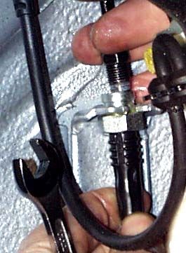
This Kit Incudes the Following:

1 pair of ST-40 4-Piston Calipers

1 set of high performance brake pads (Not suitable for track use)

1 pair of 328mm X 28mm AeroRotors

1 pair of caliper adapter brackets, with stainless steel mounting studs and hardware pre-installed.

1 pair of stainless steel covered Teflon brake lines.

        - 1 pair of “C” clips for brake line brackets (used for VW kits only)
        - 1 pair of Banjo Bolts
        - 2 pair of copper washers
        - 1 pair of rubber end caps
        - 2 High temperature Ty-Wraps

Caliper, Hat and Bracket Finish Disclaimer

Many wheel-cleaning solutions contain strong acids that may damage the finish on any caliper
and or aluminum anodized finish, especially the plating on the hardware. Check for adverse
effects by trying a small amount of the cleaner in question on an inconspicuous area. Avoid
over spraying, and rinse the cleaning solution off as quickly as possible. STOPTECH will not
be held liable for damage to caliper, hat or bracket finish due to corrosive chemical exposure.

               A level, stable and clean surface suitable for supporting the car on
                  jack-stands should be used for the installation.

                           Refer to the Owners Manual for correct location for
Step 1                     jacking up the vehicle. Jack up the vehicle and
                           secure on a pair of jack stands. Or jack one side
                           only using a single jack stand of suitable load
Jack up the car.           rating.

Apply Parking Brake and properly block rear wheels.

Remove plastic wheel nut covers using the factory supplied tool.

Brake loose the lug nuts on both front wheels with a 17mm socket (for stock wheels) before jacking up the
vehicle and secure on a pair of jack stands. Or jack one side only using a single jack stand of suitable load
rating.

                                      www.stoptech.com                                                8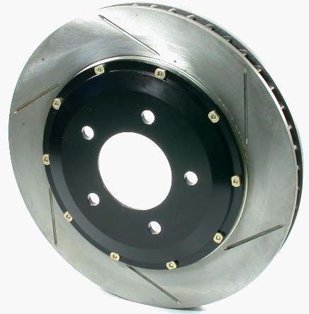
NEVER LEAVE ANY VEHICLE SUPPORTED WITH
                   ONLY A JACK, ALWAYS USE JACK STANDS.

                  Note: All Photographs Show Right Side Installation

Step 2

Remove Wheels

After securing the vehicle at a convenient height, remove
the front wheels.

Step 3
                                                                           Wheel shown may not be
                                                                           representative of vehicle
Remove Inner Brake Line Connection                                         described in this manual.

WARNING - Brake line fluid will damage most painted surfaces. Immediately clean spilled
brake fluid from any painted surfaces.
Place a drip tray or several rags directly below the inboard brake line connection. If the area around
the connection is dirty, clean with brake cleaner or appropriate cleaning agent

Note- Be sure the cap is securely installed on the master cylinder. If the cap is loose or removed,
it is likely more fluid will drip.
Using an 11mm wrench, loosen and remove the hard line fitting from the stock brake line.
Note- Brake fluid will drip onto your hands during this operation. Latex gloves may be preferred.
Be aware that brake fluid will soak through fabric or leather gloves and transfer to everything
touched after that.

                                     Removal of Clip Shown

                                     Quickly place one of the rubber
                                     caps over the end of the hard
                                     line. This should effectively con-
                                     trol fluid loss for the duration of
                                     the installation.

                                   www.stoptech.com                                                9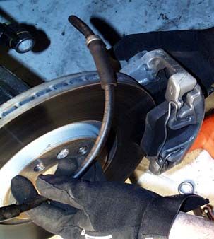
Step 4

   Remove Stock Calipers

   On left side only of the TT is a brake pad wear sensor.
                           Separate the male end of the brake pad wear
                           sensor connector (wires attached to the brake
                           pad) from the female connector (wires
                           attached to the chassis side).

                           Use a small blade type screwdriver
                           in the chassis side of the connector
                           to release the 2 parts.

   Disconnect brake line from strut as shown:

     Remove clip                                        Remove line from bracket
     Note: For Audi TT
     installations, retain
     this clip for later use.

   If not done so already, please read Step 12 on page 15. The end of the plug attached to the brake pads on the
   left side of the vehicle will need to be modified to prevent the “Brake Warning” light from coming on. You may
   want to make this modification at this point as the rotor assembly will not be in the way.

   - Loosen the stock caliper mounting bolts with a 18mm wrench or socket.

Note- Bolts are at 90 lb-ft of torque from the factory. A great deal of force is required to loosen them. It
may be necessary to turn the steering to the side you are working on so the wrench handle sticks out
clearing the wheel well. Full lock will slightly straighten out if the steering wheel not held.

                            Remove the caliper with stock line attached.
                            Be aware there may be some leakage from
                            the open end of the brake line, but it should
                            remain fairly dry unless the pads/pistons on
                            the caliper are retracted.

                                         www.stoptech.com                                                10
Step 5
Remove the Stock Rotor
Remove the Phillips head screw holding the rotor.
Note- Rust and corrosion may make this screw difficult to
remove. Be careful not to strip the screw head. If screw
does not easily come loose, try a penetrating thread lubricant
to loosen the threads. If bolt is not easily removed, consult a
professional mechanic of brake technician for assistance.
Be sure to prevent rotor from dropping as bolt is removed.
In some cases the rotor may be rusted or corroded into place. Again, a penetrating type oil may
help loosen the rotor. In severe cases it may be necessary to tap the rotor off with a non-marring
hammer or mallet.
Step 6
Install Caliper Bracket Install the caliper adapter bracket to the upright on the
stock caliper mounting lugs using the stock mounting
bolts. The pre-installed studs face forward, and the
bracket mounts on the inboard side of the caliper mounting
lugs on the upright. The round boss goes under the bolt head.
Torque the bolts to 90 lb-ft. The factory bolts have a
locking feature built into the retained washer. DO NOT use
any thread locker such as Loctite™.
Again, it may be necessary to turn the wheels in order
for the wrench handle to clear the wheel well.
Step 7
Install AeroRotor Assembly
Non-plated rotors MUST be washed with soap and water prior to installation.
Install the pre-assembled AeroRotor and aluminum
hat assembly onto the spindle using the stock Phillips head screw.
Be sure the rotor assemblies are on the correct side of
the car. Reversing the rotors will severely decrease the
cooling capacity of the system. The vanes inside the rotor
should lean to the rear of the car on the top-side of the
rotor. See green Break-In Procedure Sheet to determine
rotor direction. See next page for proper orientation.
" Rotate the rotor assembly and check that the backing plate (dust shield) is not touching the rotor.
If there is interference, simply bend the plate out of the way where there is interference.
www.stoptech.com 11AeroRotors MUST be cleaned with soap and water prior to installation. Not doing so will damage
the rotors and pads, and will prevent the brakes from performing properly.
Even though the rotors may look clean, the rust
inhibitor is in place, and it must be removed.
Not cleaning the rotors will severely impact the
performance of your new brake system.
War ning: D
arning: Doo not skip this step!
www.stoptech.com 12Left-Side Rotor
Outboard Side
Driver
er’’s Left
river
Right-Side Rotor
Outboard
Side
Driver
er’’s Right
river
www.stoptech.com 13www.stoptech.com 14
Caliper Component Identification

                 Bolt-in Bridge        Pad Retaining Clip

         Cross Over Tube                                                 Bleed Screw

                              Bridge Bolts

The ST-40 original equipment caliper uses a common Porsche-style pad.
The Friction Materials Standards Institute (FMSI) number for the pad backing plate is D372.

For further pad interchange information, please see the FAQ section of the StopTech website at:
www.stoptech.com

                                  www.stoptech.com                                       15
Step 8
Install ST-40 Calipers
Determine the left and right side calipers.
The calipers are marked on each box.
As a check, the bleed screws always
go to the top of the caliper.
Remove the Jet Nuts and washers from the
Remove the caliper bridge
studs of the caliper adapter bracket.
by gently tapping from
the inside of the caliper
with a non-marring tool
Remove the 2 bolts holding the caliper
bridge using a 5mm Allen wrench.
Note- The pad retaining clip
(rectangular wire) typically, but
not always, stays engaged with
the bridge. If it comes loose, it Note- In order to stiffen the caliper,
can be simply pressed into place the bridge is a very snug fit and the
with the weld of the clip in the bolts may be tight when coming out.
recess of the bridge. It should be Keep turning bolts while applying
centered side to side. Note pressure in the direction of removal.
orientation of bridge. The
“air-scoop” faces the smaller piston.
Caliper shown on vehicle for
reference only.
www.stoptech.com 16Step 8 (Continued)
Remove the caliper bridge by gently tapping from the inside of the caliper with a non-marring tool
such as the handle of a hammer.
Slide the caliper over the mounting studs with the bleed screws facing up.
Install the jet nuts onto each stud
with one 12mm washer under each nut.
Tighten the nuts to 40 lb-ft of
torque using a ½” socket (6 point
preferred, but 12 point will work).
Step 9
Install the brake pads
Slide the pads into position through the outboard side
of the calipers. Be sure friction side of the pad is facing
the rotor (Yes, they have been installed backward before).
Reinstall the bridge by
sliding it into position and
rocking it until one of the
holes lines up.
Note: In order to reduce caliper flex, the bridge is a precision
fit that must be aligned correctly to slide straight in and out.
The bridge is directional, in that the “air-scoop” detail should
always face the smaller caliper piston.
It may be necessary to gently tap the bridge into place with a plastic or
leather hammer. Insert the first bolt most of the way, then insert the
second bolt. Do not hammer the bridge bolts into place.
Adjust the position of the bridge until the bolts slide in more easily.
Gently tapping the bridge while pressing on the bolt works well.
Torque each bolt to approximately 8-10 lb-ft
appro lb-ft, using a 5mm Allen wrench. Do not over-torque the
bridge bolts, a torque wrench is not recommended - snug is tight enough.
www.stoptech.com 17Step 10
Install the Stainless Covered Teflon Brake Line
Slip the flat washer provided over the Banjo bolt as shown
Washer over Banjo
Washer shown over line
Install the strut bracket fitting into the strut bracket, with
the washer placed between the fitting and the bracket, and
with the banjo fitting oriented toward the caliper.
For a Volkswagen kit, press the supplied “C” clip into the
groove to secure the line.
For an Audi TT kit, reuse the stock clip, and press it into the
groove to secure the line.
Banjo fitting
Install the Banjo bolt with a copper
washer on each side of the Banjo fitting
on the brake line, and thread into the inlet port of the caliper.
Banjo bolt
Copper washers
While pointing the line toward
the strut bracket, use a 14mm
socket or wrench to tighten the
Banjo bolt to approximately14 lb-ft of torque.
Do not use a torque wrench, as overtightening
the bolt can strip the aluminum threads, caus-
ing irreparable damage to the caliper.
Remove the rubber cap from the
end of the hard brake line.
www.stoptech.com 18Step
( 10 (Continued)
Note proper installation of
line and clip in bracket
Slide the inboard end of the new
stainless line into the existing bracket
hole the old line came out of. Be
prepared to use both hands to align
the fittings as the spring clip may
keep the hard line fitting from
immediately lining up. Start the
hard line fitting into the new line
several threads by hand before using a 11mm wrench to tighten the
fitting. It will be necessary to hold the stainless brake line fitting in place with a 14mm wrench to
tighten the fitting.
Step 11
Check brake line clearance
Turn the wheels lock-to-lock and be sure the brake line is not binding in any way. If necessary, loosen the
Banjo bolt and slightly realign the brake line.
After securing the brake line, turn the wheels lock-to-lock, to ensure
that the brake line is not binding in any way
way,, nor inter fering with any
interfering
suspension component, including the CV boot and axle/driv
axle/drivee shaft.
Step 12
Modify Brake Wear Sensor (Left Side Only)
In order to prevent the “Worn Brake” indicator light from coming on, the plug from the brake pad
wear sensor needs to be modified and reinstalled.
Cut the sensor plug from the pad leaving approximately 1 ½” of both wires behind the plug.
Strip approximately ½” of insulation from each wire and twist the ends together. Twist both wires together as
well. Though not mandatory, soldering the wire ends together is desirable. Insulate the connection with shrink
tubing or high quality electrical tape.
Reinstall the plug into it’s mating connector and ty-wrap wires against the bracket.
Step 13
Bleed the brake system
Note- Complete installation on both sides before bleeding the brake system.
www.stoptech.com 19Step 13 (Continued)
Bleed system using a 11mm wrench on the bleed screws:
- The sequence for bleeding the brakes should be:
1. Right outboard bleed screw
2. Right inboard
3. Left outboard
4. Left inboard
Note: The calipers will need to fill with fluid,
quickly draining the brake fluid reservoir.
Keep a close watch on the fluid level when
initially bleeding the system. The reservoir
location on the TT is such that a small funnel
will make filling with brake fluid easier.
DO NOT LET THE MASTER CYLINDER RUN DRY AND SUCK AIR. Doing so on an ABS
equipped vehicle may require the brake system to be serviced by a certified brake technician.
After bleeding, with a constant pressure applied to the brake pedal, check all connections for leaks.
Brake fluid will damage most painted surfaces. Immediately clean spilled brake
fluid from any painted surface, including the caliper. Though caliper paint is
designed to resist harsh chemicals, prolonged exposure will damage the finish.
Step 14
Check Wheel Clearance and Install Wheels
Check wheel to caliper clearance before installing wheels - see Note below!
Note: The stock TT wheels are normally balanced on the inside with adhesive backed lead. If the
lead is on the outboard edge near the spokes, it may interfere with the caliper. If necessary note
weight and location and place a new piece of the same weight further inboard to clear the caliper.
Reinstall the wheels using the manufacturer or wheel supplier recommended torque on the fasteners. It may
be necessary to snug the bolts before lowering the vehicle and then torque the wheel bolts when the car is
on the ground.
www.stoptech.com 20Step 14
Carefully test-drive the vehicle in a safe area at low speed to insure all components are working correctly.
Follow pad and rotor break-in procedures on following page.
If there are any questions as to what you feel, hear or see during this slow drive, consult a profes-
sional mechanic or brake technician for advice, or call the StopTech Technical Support at 310-218-1091
All trademarks are properties of their respective owners. StopTech is not associated or affiliated with or sponsored by
VW/Audi.
www.stoptech.com 21AeroRotorTM Installation & Break-in Procedure
READ THIS NOW
FAILURE TO READ, UNDERST
AILURE AND AND FOLL
UNDERSTAND OW THESE PR
FOLLO OCEDURES
PROCEDURES
WILL CAUSE P
CAUSE ERMANENT DAMA
PERMANENT GE TO YOUR BRAKE R
DAMAGE ROOTORS AND KEEP
THE SYSTEM FROM WORKING A
FROM T IT
AT ’S FULL CAP
IT’S ACIT
CAPACITYY.
The majority of brake system problems are due to improper installation and/or break-in of the rotors
and pads. By reading and understanding the following, you will avoid the most common causes of
poor brake performance and vibration. FAILURE TO READ AND UNDERSTAND THIS MAY
CAUSE SERIOUS PERMANENT DAMAGE TO YOUR NEW ROTORS.
Wash Non-P
Non-Plated A
on-Plated er
Aer oR
eroR otors with SO
oRotors AP
SOAP
AND WATER befor
beforee installation.
StopTech coats non-plated AeroRotors with a water soluble, environmentally friendly rust inhibitor
that MUST be cleaned before use. A non-plated rotor looks like bare metal, plated rotors are bright
silver in color and do not need to be washed. Even though you may not see a change in the rotor color,
if the rotor is not rusty, the rust inhibitor is there. Use soap and water, NOT BRAKE CLEANER to
wash the rotors. A small piece of Scotchbrite works well to scrub with. When cleaned and rinsed
properly, the surface of the rotor will immediately show a light rust color which is normal.
Break in yyour
our new pads and rrotors
otors b
byy carefully fol-
carefully
lowing the pr
lowing ocedur
oceduree described belo
procedur below w and on the
opposite side of this page.
Breaking in rotors and pads is critical to the optimum performance of your new brakes. When
breaking in new parts, you are not only heat cycling the pads, but depositing a layer of pad material
onto the rotor face as well. If not broken in properly, an uneven layer of pad material will be depos-
ited onto the rotor causing vibration. Vir tually ev
irtually er
eryy instance of a ““warped
ever warped
warped” ” rrotor
otor is
attributed to uneven pad deposition.
Note: P lated rrotors
Plated otors must be driv en with gentle br
driven aking until CAD plating is wor
braking wornn off rrotor
otor
faces BEFORE star ting the br
starting eak-in pr
break-in ocedur
procedur
ocedure.e. D
Doo not use brakes aggr
brakes essiv
aggressiv ely until plating
essively
is wor
wornn off, typically sev er
sever al miles of driving.
eral
Typically, a heavy braking street driver will experience approximately 1 to 1.1G’s of deceleration. At
this rate, ABS will be activated on such equipped vehicles. A moderate braking effort is needed to
properly break in rotors and pads. If ABS intervention or lockup was called 100% brake effort, a
stopping force of approximately 70-80%, just short of ABS intervention or lockup is a general esti-
mate of pedal effort you are trying to achieve.
(Please see other side)
www.stoptech.comRotor and Pad Break-in (continued)
Note-
Bedding of pads should not be done in wet weather or wet road conditions.
After completing installation, make a series of 10 stops from 60 to 5-10 MPH. At the end of each stop,
immediately accelerate to 60 again for the next stop. Run all stops in one cycle.
During the 60 to 5-10 MPH series of stops, the exact speed is not critical. Accelerate to approximately
60 and begin the braking cycle. As you approach 5-10 MPH, it is not necessary to watch the
speedometer, keep your eyes on the road and approximate your speed at the end of each cycle.
DO NOT COME TO A COMPLETE STOP, AS YOU WILL IMPRINT PAD MATERIAL ONTO
THE ROTOR, CAUSING A VIBRATION.
There are several indicators to look for while breaking in the system:
On the 8th or 9th stop, there should be a distinct smell from the brakes. Smoke may be evident after
several stops as well.
Also on the 8th or 9th stop, some friction materials will experience “green fade”. This is a slight
fading of the brakes. The fade will stabilize, but not completely go away until the brakes have
cooled.
After the break-in cycle is finished, there will be a blue tint color on the rotor with a light gray film
on the rotor face. The blue tint indicates the rotor has reached the proper break in temperature and
the gray film is pad material starting to transfer onto the rotor face.
If racing or higher per for
performance pads ar
formance aree being used, add four stops from 80 to 5-10mph and
from
if a full race pad, four stops from 100 to 5-10 mph.
After the first break in cycle shown above, the brakes will still not be operating
at their best capacity
capacity.. A second or thir d bed-in cy
third cle is typically necessar
cycle necessaryy befor
beforee
the brakes rreally
eally star
startt to ““come
come in”. A ““cy
in”. cycle
cycle” is a series of stops with a cool
cle”
down in between each cycle.
StopT ech does not endorse speeding on public rroads.
topTech oads. If going abo
abovve the legal
speed limit, do so in a safe area, away from traffic at your own risk.
After the final stop of each cycle, drive as much as possible without using the brakes to cool off the
system. Ideally, the brakes should be allowed to cool to ambient temperature before using again.
DO NO
NOT T COME TO A C
COME OMPLETE ST
COMPLETE OP WHEN THE SYSTEM IS HO
STOP HOTT AND LEAVE
LEAVE
YOUR FOO
FOOTT ON THE PEDAL. PAD MATERIAL
PEDAL. PAD MATERIAL WILL IMMEDIATEL
IMMEDIATELY
TELY TRANSFER TO
THE ROTOR CA
RO USING A VIBRA
CAUSING TION.
VIBRATION.
If you have any questions about rotor and pad break in, or any aspect of your StopTech brake kit or
brakes in general, please contact our Technical Support Department at 310-218-1091 or e-mail us at
support@stoptech.comThank you for selecting STOPTECH, we know you had a
choice in selecting your big brake upgrade for your Audi TT or
Volkswagen Mark IV performance car.
We proudly support our fine products. For any assistance or
questions, please contact our Technical Support Department
at
(310) 218-1091
or email us at
support@stoptech.com
StopTech
1805 S. Wilmington Ave.
Compton, CA 90220You can also read