EN - with installation instructions for AUTOTERM ...
←
→
Page content transcription
If your browser does not render page correctly, please read the page content below
EN

                      User’s manual
                with installation instructions
            for AUTOTERM Liquid heaters.
   FLOW-5D 12V/24V      FLOW-5B 12V
            FLOW-14D 12V/24V

Manufacturer: ADVERS LLC
Novo-Sadovaja str. 106, 443068, Samara, Russia
www.autoterm.ru
Representative office of manufacturer: AUTOTERM LLC
Paleju 72, Marupe, Latvia, LV-2167
Warranty Department warranty@autoterm.com
Technical Support service@autoterm.com
www.autoterm.com

                                    v02.2021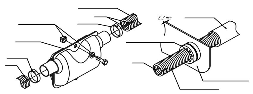
Table of contents
Introduction ......................................................................................................................... 3
1 General instructions and operating principle .............................................................. 4
2 Safety precautions ....................................................................................................... 5
Retrofitting .......................................................................................................................... 7
3 Main heater unit and assembly installation requirements ........................................... 8
 3.1 Installation of the heater .......................................................................................... 9
 3.2 The installation of the coolant system.................................................................... 10
 3.3 Installation of the air intake pipe. .......................................................................... 12
 3.4 Installation of the exhaust pipe. ............................................................................. 14
 3.5 Installation of the fuel system. ............................................................................... 17
 3.6 Installation of heater wiring. ................................................................................. 21
 3.7 Installation of the control panel. ............................................................................ 23
4 Testing the heater after installation and first launch ................................................. 23
 4.1 Automatic Control Features .................................................................................. 24
 4.2 Vehicle alarm wire start ......................................................................................... 24
5 Recommendations ..................................................................................................... 25
6 Malfunctions.............................................................................................................. 26
7 Warranty Terms......................................................................................................... 28
 Annex 1: Basic parameters & specifications of heaters ................................................. 29
 Annex 2: Connection diagrams of heaters ...................................................................... 30
 Annex 3: Size and dimensions of heaters ........................................................................ 32
 Annex 4: Electrical wiring diagrams of heaters ............................................................. 33
 Annex 5: Periodic maintenance table ............................................................................. 35
 Annex 6: Maintenance check list ..................................................................................... 36

                                                                                                                                       2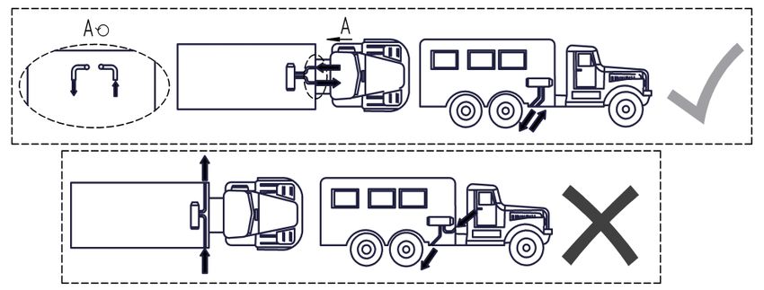
Dear Customer!
   Thank you for choosing the AUTOTERM FLOW heater! We are doing everything to
make sure this product meets your requirements. It is essential to us that the quality of our
products satisfies every customer.

    Introduction
     This manual is intended for organizations that specialize in the installation and
maintenance of AUTOTERM FLOW liquid heaters (5D 12V/24V; 5B 12V; 14D 12V/24V)
(hereinafter referred to as heaters, or 5D, 5B, and 14D for short), as well as users of the
product after installation. The document covers instructions and guidelines for the
installation of the product on a variety of land vehicles, and small maritime vessels (e.g.
yacht, boat, cutter). It also covers function tests of the product after installation, and basic
maintenance procedures to ensure the heater operates reliably.

             Please read this manual before installing and/or operating the FLOW heaters.
             This manual contains important information to use this product safely and
             correctly. Disregarding these instructions can void the warranty of the
             product, lead to damage of product and/or property, and be a health risk.

                                                                                               3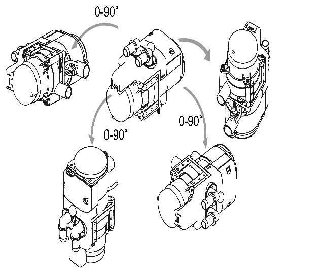
1    General instructions and operating principle
    AUTOTERM FLOW heaters are designed to be used for:
      • pre-heating vehicle engines with liquid cooling systems at an ambient air
        temperature of up to –45°С;
      • defrosting windshields, heating cabins, cargo compartments, and other confined
        spaces in vans, trucks, and maritime vessels with a central liquid heating system.

          The heater operates independently of the vehicle engine.
          The operating principle of the pre-heater consists of heating the fluid in the cooling
    system, which is pumped through the heat exchanger system.
          Fuel is supplied by a separate fuel pump from the fuel tank of the vehicle or vessel,
    or from an additional fuel tank.
          The heater can be powered by a vehicle battery or a separate battery.
          The operation of the heater is controlled by the control unit, which controls the
    temperature of the coolant fluid depending on its set parameters.
          If the coolant temperature exceeds the set temperature, the heater switches to the
    cooling mode: combustion stops, but the pump continues to circulate the coolant
    throughout the vehicle’s heating system. As soon as the coolant temperature drops to the
    pre-set temperature, the heater switches on again.
          The liquid heater continues working for between 20 to 120 minutes (determined in
    its settings), or until it is shut down. The purging duration is around five minutes.

                 Installation of the heater and its components must be carried out by
                 specialized organizations approved by AUTOTERM. Installation of the
                 heater must be carried out only by certified specialists in accordance with
                 the installation instructions.

                 If the heater is handled and/or installed improperly, there is a possibility of
                 fire hazard and damage to property because of the use of fuel and
                 electrical components. This is why all safety precautions and installation
                 instructions must be carefully read and followed.
       Basic parameters and specifications of the heaters can be found at the end of this
    manual (see Annex 1).

                                                                                                   4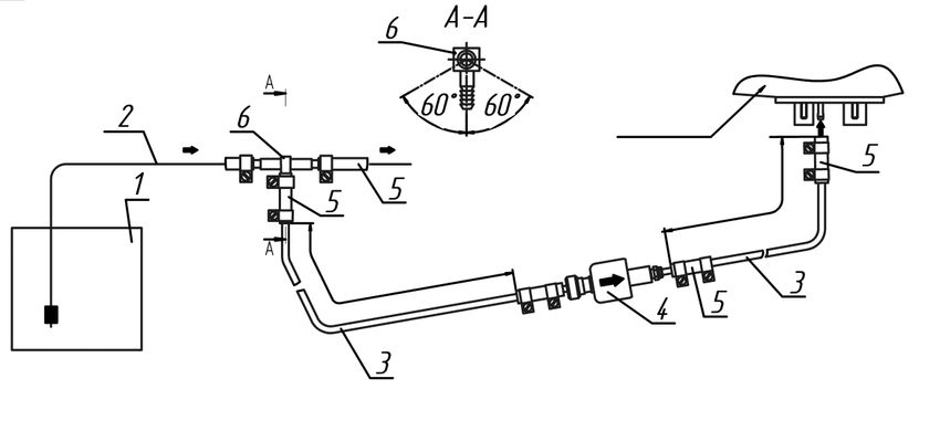
2   Safety precautions
               • Do not use or install the heater in places where flammable vapors,
                 gases, or large amounts of dust may accumulate.
               • Disable the heater when the vehicle or vessel is being fuelled.
               • Do not cover the heater with clothing, pieces of fabric and so on, and
                 do not place such objects in front of the air intake.
               • Do not install the fuel line inside the cabin of a vehicle.
               • The installation configuration must exclude the possibility of
                 contact of the exhaust pipe with the air intake, fuel pipe, or other
                 flammable objects.
               • The vehicle where the heater is installed must be equipped with a fire
                 extinguisher.
               • Do not install the heater electric wiring (harnesses) near the fuel line
                 and the exhaust pipe.
               • Disconnect the heater from its battery during repair work on the
                 heater.
               • Do not connect the heater to the power circuit of the vessel, when the
                 engine is operating and there is no battery.
               • Do not connect or disconnect heater connectors, when the heater is
                 powered.
               • When electric welding is carried out on the vehicle, or repair work is
                 made on the heater, the heater must be disconnected from the battery.
               • Disconnect the heater from the power supply when jumpstarting the
                 vehicle.
               • Do not use fuses rated differently from indicated on the electric circuit
                 diagram.
               • Do not use makeshift devices (wires etc.) instead of fuses.

                                                                                             5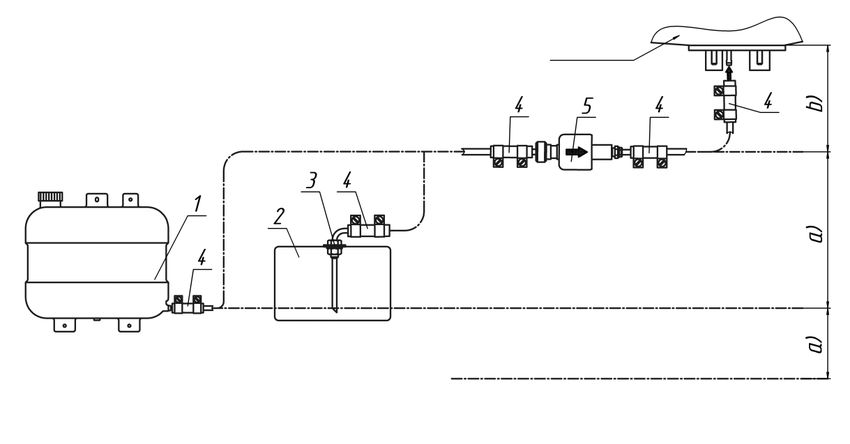
• The relevant safety precautions must be observed when working with
                coolant liquids and electrical and fuel systems when installing and
                dismantling the heater.
              • Do not disconnect power from the heater before the purge cycle
                ends.
              • When the heater has been switched off, do not switch it on again for
                5-10 seconds.
              • Due to poisonous exhaust gases and the risk of suffocation, DO
                NOT use the heater in closed and/or unventilated places (e.g.
                garage, workshop, etc.)
              • Do not step on the heater or put any objects on it and in it.
              • Electric wiring, the air intake, and the fuel pipe must be protected
                from contact with sharp edges of vehicle structures.
              • If any work was done on a cooling system (repair or replacement of
                coolant), it is necessary to bleed the system.
              • For safety reasons, contact the service shop to troubleshoot the heater
                if it fails to launch twice in a row.
              • In case of faults in the operation of the heater, contact only specialized
                repair organizations authorized by AUTOTERM.

If the consumer fails to follow the requirements above, the warranty of the heater
becomes null and void.

                                                                                         6
Retrofitting
When replacing a different brand of heater for an AUTOTERM FLOW heater, be sure
to first check the following things:
Diameter of the exhaust pipe.
The FLOW-5D and FLOW-5B have an exhaust pipe with an internal diameter of 24mm,
and the FLOW-14D has an exhaust pipe with an internal diameter of 38mm.
Some brands use exhaust pipes with different diameters. If so, it needs to be adjusted to
a diameter suitable for the heater in use. Larger diameters can be used if needed. (see
“Section 3.4”, for more information on installing the exhaust pipe).
Disregarding these instructions can lead to an insufficient output of exhaust
gases due to backpressure, thus damaging the heater.
Fuel system.
When retrofitting a heater, all old fuel pipes and fuel pumps must be completely
removed, and a suitable fuel system for the AUTOTERM FLOW heater must be installed
in its place.
Different brands of fuel pumps may have different fuel outputs, and their fuel pipes may
have a different diameter. (see “Section 3.5”, for more information on installing the fuel
system).
Disregarding these instructions can cause fuel to overflow in the heater, or
lead to an insufficient flow of fuel, thus damaging the heater.
Electrical wiring.
All old wiring, electrical connections, control panels, etc. must be removed and installed
with new AUTOTERM FLOW components. (see “Section 3.9”, for more information on
installing the wiring of the heater).
Electrical related faults are common when using different and unsuitable
electrical components.
Coolant system.
When retrofitting a heater, all old coolant pipes and water pumps must be completely
removed, and a suitable coolant system for the AUTOTERM FLOW heater must be
installed in its place.
Different brands of circulation pumps may have different liquid output and coolant pipes
may have a different diameter. (see “Section 3.2”, for more information on installing the
coolant system).
Disregarding these instructions can cause the heater to overheat, thus
damaging it.
7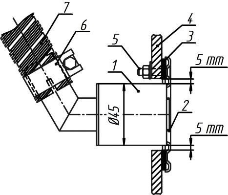
3   Main heater unit and assembly installation requirements
      The heater can be installed inside, and outside of the vehicle. Install the heater in a
dry place that is protected from water, condensation, dirt, excessive vibrations, heat
emissions, engine emissions, and fuel or oil contamination.
               When installing the heater in a cargo hold of the vehicle, install the heater
               at a height and location that prevents contact with cargo and in a way that
               the cargo will not obstruct the air intake for the combustion and exhaust
               systems.
               When installing the heater in the engine compartment, under the front
               bumper or under the vehicle, make sure that it is protected from road spray,
               rocks, or other contaminants.
               It should never be submerged in water or any other type of liquid.

               The heater must be installed below the level of the coolant expansion
               tank.

               When installing the heater on a maritime vessel, it must be protected from
               water.
               Consider the maximum heel of the vessel. Maximum heel must not bring
               water into the discharge channel for exhaust gases. Bilge and water must
               also not get on the heater.

               The heater cannot be installed in coolant systems where coolant system
               pressure can exceed a pressure of 2.1 bar.

       The heater must be installed following safety requirements and taking into account
the type of vehicle or vessel being used. Consider everything related to peripheral
equipment, for example, the maximum permissible length of the exhaust gas channel, the
intake of air for combustion, the location of the passage in the board (for maritime vessels),
the layout and length of electric wires, the distance from the fuel tank, and the layout of the
coolant pipes.
       All precautions must be observed when installing the heater to reduce the risk of
injuries to personnel, or damage to the equipment.

                                                                                               8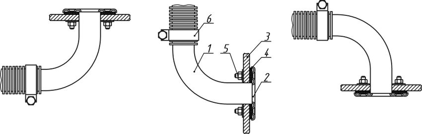
3.1 Installation of the heater
       Install the heater, taking into consideration the permissible operating position
  according to Fig.1. Take into account the possible heel of the vessel, if installing on
  maritime transport.
        When the heater is positioned with the exhaust pipe facing downwards, it is
  considered the 0° position. FLOW-5D and FLOW-5B have only two mounting positions
  – 0° and 90° with the air pump pointing upwards. The FLOW-14D should not be tilted
  (see Fig.1).
                                                                               Admissible angle of slope

                                 Fig. 1 - Mounting positions of the heaters

                 WARNING!!! The reliable operation of the heater depends on the
                 correct installation! The heater must be installed according to Fig.1.

                                                                              Fig. 3 - Mounting of FLOW 14D
       Fig. 2 - Mounting of FLOW 5

     The FLOW 5 must be fixed to the mounting bracket with at least three M5x12 bolts,
tightened with a force of 10 Nm. The mounting bracket may be installed vertically or
horizontally. The mounting bracket must be fixed to the body of the vehicle with four M6
bolts, tightened with a force of 11.8 Nm (see Fig. 2).
     The FLOW 14D standard bracket is fixed to the body of the vehicle or vessel with four
M8 bolts, tightened with a force of 22 Nm. (see Fig. 3) It is recommended to install the
heater under the bonnet of the vehicle or in the engine room of the vessel.

                                                                                                              9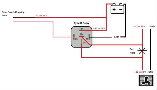
When installing the FLOW series heater make sure that the heater is
                   protected from any road spray, dust, water, and moisture.
                   The heater must be fixed properly to bypass any vibrations. It must be
                   installed in a well-ventilated area.
                   DO NOT install near flammable or heat-sensitive objects such as sails,
                   fenders, clothing, sheets, paper, gas pipelines, fuel tanks, etc.

3.2 The installation of the coolant system
     Connect the liquid heater to the cooling system of the vehicle so that it is aligned to
the direction of the coolant flow within the cooling system (Fig. 4a/b).
                                                                OUT

                                                   IN

     Fig. 4a – Coolant flow direction for FLOW 5   Fig. 4b – Coolant flow direction for FLOW 14D

     During installation, use the rubber hoses and shaped pipes included in the installation
kit of the heater. The hoses must be laid avoiding sharp bends or crimps and it must be
possible to maintain them in a raised position from the heater to ensure unrestricted air
bleeding.

            When laying the hoses ensure that they are not installed beside the exhaust
            system and engine parts, which are heated to a high temperature.
            Before the first start of the liquid heater and after a change of coolant, ensure
            that the device is properly bled. The presence of air in the system could result
            in overheating of the liquid heater.

            Make sure that all pipe joints are properly tightened and leak proof.

                                                                                                   10
3.2.1 Installation of the coolant pump
The coolant pump must be installed in the cooling circuit upstream of the liquid
heater. The coolant pump should be installed below the level of the expansion tank,
radiator, and heater.
The direction in which the coolant flows in the pump must be the same as in the
cooling system of the vehicle/vessel.
The installation position of the coolant pump must not cause an airlock inside
the pump. See the permissible installation positions in Fig.5.
Fig. 5 – Position of the coolant pump
3.2.2 Angle pipes
To assist the installation process, the angle pipes can be turned by 180° for FLOW 5
or by 90° for FLOW 14D (see Fig. 6a/b).
To turn the pipes, loosen the screw in the fixation plates. Turn the pipes to the desired
position and retighten the screw in the fixation plate.
Fig. 6a – Angle pipe fixation for FLOW 5 Fig. 6b – Angle pipe fixation for FLOW 14D
Do not rotate the pipes while the screw is being tightened. It will damage the
gaskets and cause a leak.
Angle pipes can be changed for straight pipes in the FLOW 5 (sold separately).
113.3 Installation of the air intake pipe.
The air for combustion must not be taken from the interior, living space, engine
or luggage compartment of the vehicle or vessel. Air should be taken from well-ventilated
areas or from outside of the vehicle or vessel.
The maximum length of the air intake pipe is 2 meters. The air pipe must be as short as
possible (cut to the minimal length if required)
Make sure FLOW 14D air intake does not touch any rainwater or dirt blockage.
The heater must not be used without an air intake pipe.
Heater
Clamp 25x40
Air intake
pipe
Fig. 7a – Connection of the air pipe to the
FLOW 5 Air intake
Fig. 7b – Air intake of the FLOW 14D
The air intake pipe is connected directly to the pipe
of the heater and fastened with a clamp. (Fig.7a).
When laying the air intake pipe, avoid sharp bends
and do not obstruct the opening of the air intake pipe
with foreign objects. Make sure the opening is pointing
downwards (see Fig. 8).
Fig. 8 – Position of air intake/exhaust pipe
If that is not possible, a Ø3mm hole needs to be drilled at the lowest point of the pipe.
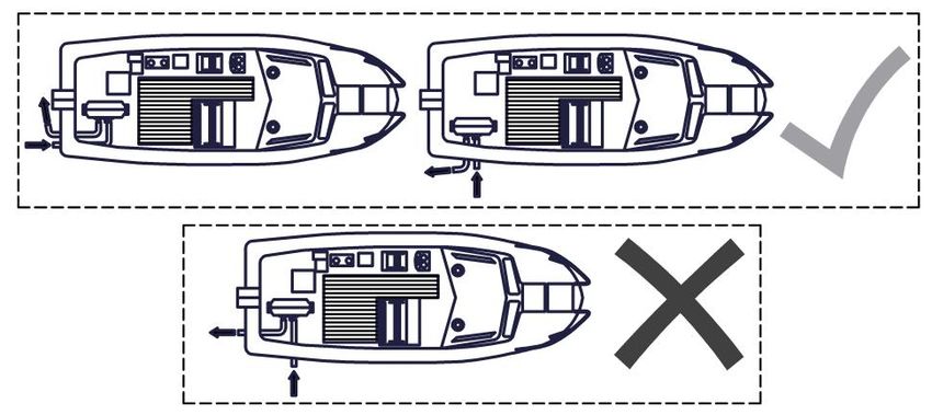
The correct installation of the exhaust and air intake pipes is when they are on the same side
(Fig.9a/b). The distance between them should exclude the re-suction of exhaust gases
through the air intake (at least 20 cm).
Fig. 9a - Location of intake and exhaust pipes on land vehicles
12Fig. 9b - Location of intake and exhaust pipes on maritime transport
Disregarding this recommendation can lead to the opposite movement of
the flame towards the air pump fan, resulting in the melting of the air pump
fan, and to the burning of the heater.
The air intake must not be installed in the movement direction of the
vehicle/vessel.
In cases when the intake of clean air cannot be ensured, such as off-road
and special purpose vehicles, please mount the dedicated AUTOTERM air
filter (assy.2684)
3.3.1 Installation of the air intake pipe on maritime vessels
Air intake from well-ventilated areas
Ambient pressure and sufficient ventilation using outside air must be present in the
air intake zone. Increased or reduced pressure in the air intake zones is not permitted. It
is recommended that the air duct is attached along the entire length of the vessel's hull of
using plastic clamps when possible. Put a cap on the end of the air duct to protect it from
drawing in foreign objects.
Air intake from outside of the vessel.
An air intake pipe (Fig.10) should be used to take in the air from outside. Make an
opening of Ø26+1 mm in the board of the vessel to install it. Install a rubber gasket between
the flange of the air intake pipe and the hull of the vessel. Attach the air duct using three
bolts as shown in Fig.10. Attach the air duct to the air intake pipe using the clamp.
It is recommended to attach the air duct along its entire length to the hull of the vessel
using plastic tie straps when possible. Make a 3mm opening in the bottom point of the air
duct to drain condensation or any water that has penetrated the air intake pipe.
Do not place the intake opening of the air intake pipe in front of the incoming
air flow of the moving vessel.
13Fig. 10 - Installation of the air intake pipe
1 – Air intake pipe; 4 – Gasket;
2 – Flange of the air intake pipe; 5 – Fastener assembly;
3 – Hull of the vessel; 6 – Clamp.
3.4 Installation of the exhaust pipe.
When installing the exhaust pipe, take into
consideration the high temperature (up to 500°С) of the Heater
exhaust pipe when the heater is in operation. Cut the
exhaust pipe (flexible crinkled metal hose, maximum
length – 2 meters) to the necessary length. It is advised to Clamp
use a two-layer exhaust pipe when installing the heater.
Attach the exhaust pipe (Fig.11) using clamps and install Metal exhaust pipe
it so that it is slightly inclined to the bottom, in the
direction of the exhaust. Install heat insulation on the
exhaust pipe to protect individual sections of the vessel Fig. 11 - Attachment of the metal pipe
to the heater
(wiring or other heat-sensitive objects).
Install the exhaust pipe to avoid the possibility of repeated intake of exhaust
gases by the air intake pipe, and make sure that no exhaust gases enter the interior
or are drawn in by the fan through the cab heater radiator.
At the end of the exhaust pipe, a shield is installed, which is necessary for stable
operation at low heating modes (Fig.13).
In the absence of the shield, air will be blown back Cut 15 mm
into the exhaust pipe. This leads to increased heater Shield
sooting and impairs heat capacity. Exhaust gases must be
expelled outside of the vehicle.
An airtight exhaust silencer is provided with the
heater. This means it can be mounted in small vessels
and confined spaces. When mounting the exhaust
silencer on the outside of the vehicle, a Ø5mm hole
Heat insulation
needs to be drilled at the bottom of the silencer (see Fig.
14a).
Fig. 13 – Exhaust pipe shield
14If the desired mounting situation requires the exhaust
silencer to be mounted vertically, the condensation drain
hole must be drilled, as shown in Fig. 14b, to avoid the
build-up of condensation in the exhaust silencer. If that is
not possible, it is recommended to install it sideways (see
Fig.14a). Silencer
Condensate
The outlet of the exhaust pipe must be installed 5mm drill bit drain hole
pointing downwards (Fig. 8), and in such a position that Fig. 14a – Condensate drain hole for
would prevent the clogging or invasion of snow and dirt, horizontal mounting
and also provide a free drain for any water that gets into
it.
When installing on a maritime vessel, the silencer
must be mounted using the bolt and nut provided, so it
will be in a fixed position.
Make longitudinal cuts (about 15mm) (see Fig. 11, Silencer
Fig. 13, Fig.15) on the ends of the metal hose to ensure
better sealing when connecting the heater pipe to the pipe
for discharge of exhaust gases through the board of the
vessel, but without going beyond the pipe to be covered. 5mm Condensate
drill bit drain hole
A rubber bushing (sold seperatly) must be used if
exhaust pipe goes through plastic parts. For example, the Fig. 14b – Condensate drain hole for
bumper of a vehicle (see Fig. 15). vertical mounting
Exhaust pipe
Cut Insulation
Bolt and nut for Clamp
fixation
Silencer Rubber bushing
Clamp
Cut
Cut
Plastic partition
Exhaust pipe
Fig. 15 - Attachment of the exhaust pipe to the heater and usage of rubber bushing
The exhaust pipe needs additional insulation at every connection of the
metal hose. For example, use a heat-resistant tape or sealant to prevent any
leaks of exhaust gases at connection points.
Additional heat insulation must be installed at all places where the exhaust
pipe goes through the floor or the sidewall of the vehicle (Fig.16) to avoid an
unnecessary fire hazard.
15If the exhaust pipes of the heater run through the living space or confined
space of the vehicle/vessel, solid stainless-steel pipes must be used. Flexible
exhaust pipes are only suitable for external use and use in engine rooms.
Insulation
Fig. 16 – Installation of additional heat insulation
The end of the metal hose should not contact the rubber seal of the heater. It is highly
recommended to install the exhaust gas discharge system in such a way that does not
allow the exhaust gases to flow inside areas used by people; such as the driver's cabin or
the living quarters of a maritime vessel (e.g. away from open windows, doors), to avoid
the possibility of inhaling dangerous exhaust gases.
Do not place the output opening of the exhaust pipe in front of the
incoming airflow of the moving vehicle or vessel (see Fig. 8).
3.4.1 Installing the exhaust adapter on maritime transport
Exhaust gases are discharged away from the vessel. Install the discharge of the
exhaust gases in a location inaccessible to water (at least 60 cm above the waterline) and
to avoid the possibility of re-intake of exhaust gases by the air intake pipe.
To install the exhaust pipe adapter (hull fitting), drill a hole in the hull of the vessel
at least 5 mm larger in diameter than the actual outer diameter of the hull fitting. Install
the exhaust pipe into it as shown in Fig.17 with the pipe looking upwards (to avoid water
infiltration). Install a rubber gasket between the flange of the exhaust pipe and the hull of
the vessel to seal the connection.
To prevent exhaust gas leaks or the exhaust
pipes falling off, it is advised to use exhaust cement or
a different kind of sealant on every connection of the
exhaust pipe. Sailboats should not install the exhaust
adapter on the side of the hull, only at the stern.
1 – Exhaust pipe adapter; 5 – Fasteners;
2 – Flange of the exhaust pipe; 6 – Clamp;
3 – Gasket; 7 – Metal hose.
4 – Hull of the vessel;
Fig. 17 - Installation of the exhaust pipe
163.5 Installation of the fuel system.
Do not operate the heater using biofuel.
Use only diesel fuel standard EN590 and petrol fuel standard EN228, depending
on the ambient temperature.
Use the instructions detailed in Fig.18 and Fig.21 to install the fuel system. The fuel
pump and the fuel supply line must be protected from heating.
It is recommended to install a small inline fuel filter before the fuel pump. Make sure
the filter is filled with fuel, and that you are using fuel lines of the same diameter as the
heater.
Do not take fuel from the fuel filter or its casings, as doing so causes fuel leaks.
Do not take fuel from the fuel line between the fuel filter and fuel pump of the
vehicle’s engine, the return line of the engine, or after the high-pressure pump
of the vehicle.
The heater is not designed to work with such high pressure.
The fuel line system should be as short as possible. The recommended
maximum length of the fuel line is 5m. The distance between the fuel tank and
the fuel pump should not exceed 1m, and the distance between the fuel pump
and the heater should not exceed 4m (see Fig.18 and Fig.21).
3.5.1 Fuel suction using a fuel suction hose.
Before installing a fuel suction hose in the fuel tank of the vehicle or vessel,
make sure that the fuel level is high enough to ensure operation of the heater
and low enough to easily remove the fuel tank if needed.
Heater
1 – Fuel tank of the vehicle 3 – Fuel line 5 - Coupling
2 – Fuel suction hose 4 – Fuel pump
Fig. 18 - Example of fuel supply to the heater with fuel suction hose
17Fuel is taken directly from the fuel tank
of the vehicle or vessel, or from an
additional tank. Drill a Ø16mm hole in the
fuel tank to install a fuel suction hose. When
drilling the hole in the fuel tank, follow
safety precautions that should be observed
when working with any transport, filled
operating with fuel or explosive substances.
If needed, cut the immersible tube of the Fig. 19a – Installation of the Fig. 19b – Installation of the
fuel suction hose to make it shorter before fuel suction hose washer
installation. The bottom end of the tube
must be located about 10-15 mm above the bottom of the tank, or at the height at which fuel
for engine can be provided to the fuel tank at any time. The cut at the end of the fuel suction
hose must be made at a 45° angle to the axis of the tube. Remove all burrs from the cut after
the work is done.
Install the fuel suction hose in the fuel tank as per Fig.19a. Install the special washer
of the fuel suction hose in the tank hole as per Fig.19b. Apply a fuel-proof sealant on the
threaded surface of the fuel suction tank to properly seal the connection between the fuel
suction hose and the fuel tank.
Never install the suction hose on the side of the fuel tank. It must be installed
on the top side of the fuel tank.
3.5.2 Fuel suction from an additional fuel tank Wall/hull of the
vehicle/vessel
Consider the convenience of fuelling, while installing the fuel Fuel tank
tank (Fig.20). Install the fuel tank in such a way that the amount cap
of fuel and its potential leaks from the inlet, fuel suction nozzle
or connections can be visually controlled. Fuel tank
When filling the fuel tank, be careful not to spill
any of the fuel on the exhaust system, wiring or
other objects, which can be damaged due to their
contact with fuel.
The fuel tank must be installed with its wide Bracket
side perpendicular to the direction of the
movement of the vehicle/vessel (see Fig. 20). Direction of movement of the
vehicle/vessel
Fig. 20 Installation of the
fuel tank
183.5.3 Fuel suction from the fuel tank of the vehicle.
Fuel is taken from the fuel line of a vehicle using a T-piece (see Fig.21). This method
can only be used if there is no pressure in the fuel line. If the vehicle is equipped with a
low-pressure fuel pump in the fuel tank, then those fuel lines cannot be used, fuel suction
hose must be installed instead. Keep in mind the installation position of the T-piece.
Heater
1 – Fuel tank of the vehicle 4 – Fuel pump
2 – Fuel line of the vehicle 5 - Coupling
3 – Fuel line 6 – T-piece
Fig. 21 – Fuel suction using a T-piece
3.5.4 Installation of the fuel pump and the fuel supply line.
The fuel pump is connected to the heater through its own harness and supplies fuel
depending on the required heat capacity to the combustion chamber of the heater. The
fuel pump is operated by electrical impulses sent by the control unit. When operating, the
fuel pump makes a characteristic, metallic clicking noise.
It is recommended to install the fuel pump
close to the fuel tank (the distance should not
exceed 1 meter (see Fig.18 and Fig.21)) and below
the low level of fuel in the fuel tank, but not lower
than 70cm of the minimal fuel level (see Fig.23,
point a)). But the distance between the fuel pump
and the heater cannot be greater than 1,5 meters
(see Fig.23, point b)). The fuel pump should be Fig. 22 – Installation angle of Advers fuel pump
positioned with a slight angle pointing upwards (1) and Thomas Magnete (2) fuel pump.
(see Fig.22).
19If for some reason the fuel pump seal is compromised, it is advised to install the fuel
pump lower than the heater to avoid leaks and flooding the heater with fuel due to gravity.
Remember to properly bleed the “silent” TH11 fuel pump. If it’s not properly
bled it will be as loud as a standard fuel pump.
To bleed it start the heater and position the fuel pump with its outlet upwards
until there are no air bubbles in the fuel line and only then secure the fuel pump
to its recommended position.
a=70 cm Heater
b=1,5 m
Fuel line
Minimal level of fuel
1 – Additional fuel tank; 4 – Coupler; Recommended level for installation of fuel pump
2 – Fuel tank of the vehicle; 5 – Fuel pump
3 – Fuel suction hose;
Fig. 23 – Height position of the fuel pump in the fuel system
Attach the fuel pump to the flexible rubber clamp (supplied with the heater), to reduce
the transfer of noise to the frame of vehicle or hull of the vessel (see Fig. 24).
Proceed as instructed on Fig.18 and Fig.21 to install the fuel supply lines. Use clamps
to attach the fuel supply lines. Do not tighten the clamps too much in trying to avoid leaks
as clamps break easily if tightened with too much force.
It is preferable to lay the fuel supply line on a straight line and with a small inclination
upwards in the direction of the heater. The fuel supply line should be fastened at equal
distances to prevent sagging, mitigate the effects of vibration and to avoid fractures. Do not
allow the fuel pump and the fuel supply line to come in contact with hot objects. Cut the
fuel supply line using only a sharp knife as per Fig.25. At the locations of cuts, there should
be no narrowing of the flow cross-section of the fuel line, dents or kinks.
Fig. 24 - Flexible rubber Fig. 25 - Cutting of the line before installation.
clamp
203.5.5 Installation of the electrical harness of the fuel pump.
If the length of the wiring harness of the fuel pump needs to be shortened, it is
permissible to remove the unnecessary portion from the middle of the harness.
The connection point must be insulated.
Never connect the fuel pump to a continuous DC power supply. It will burn the
coil of the fuel pump.
Installation of the electrical harness connector of the fuel pump is shown in Fig.26.
Make sure that the wiring of the fuel pump is installed in the right way before inserting
the pins of the wiring in the plastic casing.
Make sure the pins are inserted all the way to the end and that they lock securely in the
plastic casing. When correctly inserted, a small click can be felt. The polarity of the pins
does not matter.
Plastic casing of connector Pins
Wire
Seal
Fig. 26 - Installation of the connector of the electrical harness of the fuel pump
3.6 Installation of heater wiring.
Install the electric harnesses of the heater according to the diagram of heater
electrical connections. (see Annex.4).
When installing electrical harnesses avoid all possibility of them being heated.
Install all the wire harnesses and electrical elements in dry and protected places. No
deformation or wire movement is permissible when the vehicle or vessel is operating.
IMPORTANT!
Fuses must be removed before installing electrical harnesses.
The battery of the vehicle or an auxiliary battery powers the heater. Control the
charge of the battery on a regular basis. It is recommended to disconnect the heater from
the battery to avoid discharge during long dockage or storage of the vessel or vehicle. Do
not disconnect the heater from power before the purge cycle ends.
The heater must be connected to an uninterrupted power supply at all times. Cutting
the power to the heater will result in loss of settings (clock, operation mode and settings).
If the heater is connected to an existing electrical installation, the wiring should be
of sufficient diameter to prevent a voltage drop (main cause of error 15). It is always
recommended to connect the heater directly to the battery of the vehicle/vessel or
auxiliary battery. It is strongly recommended to use new and provided wiring for
installation of the heater.
213.6.1 Installation of the relay
Relay is sold separately
The relay is necessary to connect the FLOW pre-heater to the interior fan of the vehicle.
When the coolant set temperature (see operation manual of the control panel) is reached,
the relay activates the interior fan of the vehicle.
In some cases, the switch of the interior fan of the vehicle must be turned on for
this feature to work.
For vehicles with a climatronic heating system an additional relay may be
needed.
Connect the relay according the connection diagrams (Fig 27 and Fig. 28)
It is important to solder the connections of the wires and to properly insulate the
connection.
Fig. 27 – Connection diagram for FLOW 5
Fig. 28 – Connection diagram for FLOW 14D
223.7 Installation of the control panel.
The control panel is intended for the operative control of
the heater. Install the panel in a convenient (appropriate) place
protected from water. The panel is attached using double-
sided adhesive tape or a standard bracket (Fig.29). The wire
may be brought out of the panel casing through the back cover
or the partition of the inner surface of the panel casing. Before
installation, degrease the surface where the panel is to be
installed. Remove protective film from adhesive tape and
install the panel on the prepared surface.
Fig. 29 – Installation of the
control panel PU-27 using a
mounting bracket.
Never extend the cable of the control panel itself as it is transmitting a digital
signal. In the event of a bad connection, this will result in malfunctions.
Use designated control panel wiring extensions.
4 Testing the heater after installation and first launch
The heater can only be put in operation when the system has been fully installed!
After installation, check:
- tightness of the air intake, exhaust, and fuel pipes clamps
- tightness of the coolant system clamps
- battery voltage
- the secure attachment of harness’ electric contacts and heater assemblies.
Fill the main fuel line with fuel, preferably using a fuel-priming device. These can be
ordered from official dealers. When the fuel system is filled, check that the fuel supply line
is sealed.
Start the heater and check its operation in minimum and maximum modes. Check
tightness and sealing of all exhaust connections, as well as air intake and coolant pipes.
Make sure there is no air in the coolant system. Run the heater for about 2 hours.
During first time operation, the exhaust pipe might emit some smoke for a
short period of time.
The launch process of the heater starts with less than a minute-long power-on-self-test.
During that time the heater self-checks its components for errors. During this phase all
components are powered up once, which results in a single audible pump click, a short fan
burst, and internal checks of glow plug and sensors. After that it starts a phase of heating
the glow plug to remove any fuel vapours remaining from the previous work cycle. This
lasts for up to 120 seconds and is a silent process.
After the purge ends, the process of ignition starts and the continuation of the set mode.
This means that the fan will slowly start to rotate and fuel pump start to click.
23Before starting to heat the coolant, the pump will start to check if the
heating liquid is frozen. The heater will then power up to 100% to heat up
the combustion chamber and to provide proper burning temperatures.
Depending on the ambient temperature and model of the heater, this
process can take up to 15 minutes.
Hot liquid only flows after the heat exchanger is heated up. This process
takes up to 3-5 minutes depending on the ambient temperature and the
heater model.
IT DOES NOT HAPPEN INSTANTLY.
Stop the heater. When the heater is stopped, the fuel supply stops, and the combustion
chamber and the heat exchanger are vented to reduce temperature.
After the first launch, please test the heater with the vehicle/vessel running engine to
check for possible fuel and/or power supply problems.
During the first few hours of operation, the heater can emit an unpleasant
smell. To get rid of the smell, run the heater for several hours on maximum
power. Ensure good ventilation.
The insulation of exhaust pipe has to burn-in. This process can also cause
an unpleasant smell.
4.1 Automatic Control Features
1) If for some reason the heater did not start, the start-up process will be automatically
repeated. After two failed attempts the heater will be switched off;
2) If burning is interrupted during heater operation, the heater automatically re-starts.
Restarts after consecutive flameouts are performed up to three times;
3) In case of overheating of the heater coil (for example due to a blocked intake or output
of the heating unit), the heater automatically switches off;
4) If the maximum temperature of the heated coolant is exceeded (for example, due to
air trapped in the coolant system), the heater automatically switches off;
5) If voltage drops below 20V (10V) or increases to more than 30V (16V), the heater
automatically switches off.
The numbers in brackets are for the heaters with a nominal voltage of 12V;
6) If the heater switches off due to an emergency situation, a malfunction code appears
on the control panel.
7) In case one of the temperature sensors is faulty, the heater will not start, and a
malfunction code will appear on the control panel.
4.2 Vehicle alarm wire start
Heater can also be started with vehicle alarm wires in two ways:
• If the brown and white wires are connected to an impulse relay (with an impulse
between 1-3 seconds), the heater will work on previously set work mode for two hours.
• When the brown and white wire is connected continuously (for example, using a rocker
switch) the heater will work on previously set work mode as long as these wires are
connected (i.e. the rocker switch is on).
245 Recommendations
If the heater does not start after switching on, make sure there is fuel in the tank, check
the charge of the battery, check if all connectors are properly connected and if the 25A fuses
are viable.
If you are unable to find the primary cause of a fault, contact your nearest dealer or
service centre, or check the website www.autoterm.com.
WARNING!
When starting the heater for the first time after installation, it is preferable
to fill the main fuel line up to the input nozzle of the heater using a priming
device. If there is no priming device, start the heater several times until the
main fuel line is filled.
It is important to remember that if the heater has not started after activation,
the control unit will restart the heater in automatic mode. If the heater does
not start after two attempts, a fault code will be displayed on the control
panel. (Look for fault codes table in “Section 6 – Malfunctions” in this
manual)
For correct operation, the heater needs regular (annual) maintenance. Stop the heater
and let all system parts cool down before any maintenance or repair work:
- check for corrosion on electrical plugs and contacts (with the battery disconnected);
- check the fuel and coolant hose seals;
- check the exhaust gas system for corrosion and sealing;
- check if the air intake pipes and air ducts are clean;
- check all air ducts for damage;
- run a computer diagnostic of the heater.
Periodic, preventative maintenance is important and must be carried out to
ensure reliable operation of the heater. See the table of periodic maintenance
in “Annex 5”.
To ensure the reliable operation of the heater, switch it on at least once a month
for 20 minutes, including during the warm seasons of the year when the heater is out
of operation. This action is necessary to remove any viscous film sediments on the
moving parts of the fuel pump. Failure to do so may lead to premature failure of the
heater.
For diesel heaters. If separate a fuel tank is used, fuel in the system has to be
changed at least once a season. Before the start of the heating season, check the fuel tank.
If the tank stored fuel for a long time (for example from the past heating season), it is
necessary to drain it! Rinse the tank with gasoline or kerosene and fill it with fresh diesel fuel.
This procedure is designed to remove sediment formed in the fuel during prolonged storage.
Failure to follow this procedure can lead to clogging or failure of the fuel pump and increased
sooting in the combustion chamber.
In case of extended parking or vessel/vehicle storage, disconnect the heater from the
power source (battery) to prevent it from discharging (current out of season heater
consumption is (30 ÷ 40) mA).
256 Malfunctions
Malfunction Recommended troubleshooting
Code Cause of malfunction
description methods
1. Check the entire liquid circuit for air
blocks.
Overheating 2. Check the pump.
Temperature near one of the
01 (upper temperature 3. Check the overheating sensor and the
sensors exceeds 120ºС
limit exceeded) temperature sensor.
4. Check the antifreeze for suitability at
current ambient temperatures
Temperature
03
sensor 1 fault Short or open circuit in the
Replace the sensor assembly
Temperature electric wiring
04
sensor 2 fault
Flame detector Short circuit to frame or open
05 Check the flame detector
fault circuit in the detector wiring
Control unit The temperature sensor is faulty
06 temperature sensor (located in the control unit, Replace the control unit
fault cannot be replaced)
Short or open circuit, control Check the glow plug.
09 Glow plug fault
unit fault Check the control unit
Air blower fault. Foreign particles obstructing
Check the electric wiring.
10 Speed lower than spinner movement, or the
Check the air blower for dirt
rated spinner hits the air blower cover
Check voltage at ХS2 connector on the
Shutdown due to Power supply voltage heater. Check fuses, the battery, the
12
overvoltage is above 16 V vehicle voltage regulator, and power
supply wiring
Check the fuel line, the fuel pump, and
the air blower. Check the exhaust pipe.
All attempts to Failure to ignite
13 Check the combustion chamber, clean
start failed (after two attempts)
the opening in the plug nozzle of the
combustion chamber if necessary
Check for short or open circuit of the
Short or open circuit of current-
14 Pump fault pump wiring; check the pump.
conducting parts
Clean the pumping elements of the pump
Check voltage at ХS2 connector on the
Shutdown due to Power supply voltage heater. Check fuses, the battery, the
15
undervoltage is below 10 V vehicle voltage regulator, and power
supply wiring
Check the air intake and the gas exhaust
Ventilation time The flame detector is not cooled
16 pipe. Check the flame detector; replace if
exceeded down by purging sufficiently
necessary
Fuel pump fault Short circuit in the fuel pump
17 Check the fuel pump
(short circuit) wiring
No communication Short or open circuit in the
between the electric wiring between the Check the 5 A fuse.
20
control unit and liquid heater and the control Check circuits and terminals
the control panel panel
26Malfunction Recommended troubleshooting
Code Cause of malfunction
description methods
Poor conditions for Check the air intake, the gas exhaust
Flame blow off in
combustion. Lack of fuel/air, pipeline, and fuel supply, resolve the
21 the “WARMUP”
the heat exchanger is fouled, the fault(s), and replace the fuel pump and
mode
exhaust pipe is clogged the flame detector if necessary
Fuel pump fault Open circuit in the fuel pump
22 Check the fuel pump
(open circuit) wiring
Rapid temperature 1. Check the entire liquid circuit for air
Possible overheating near one
change indicated blocks.
24 of the temperature sensors due
by one of the 2. Check the pump.
to poor coolant circulation
sensors 3. Check the overheating sensor and the
The coolant is The liquid heater goes into the temperature sensor.
25 being heated up cooling down mode three times 4. Check the antifreeze for suitability at
too quickly in one cycle in less than 6 min current ambient temperatures
The motor does not rotate
27 Air blower fault (movement is possibly
Check the fuel system. Check the
obstructed)
secureness of the fuel line clamps, the
The motor rotates
seal of the fuel line and the fuel pump
uncontrollably (possible fault in
28 Air blower fault nozzle, as well as the fuel pump capacity
the 5 V power supply to the
control unit)
All ignition Check the fuel system. Check the
attempts failed Ignition has been tried more security of the fuel line clamps, the seal
29
with the liquid than four times of the fuel line and the fuel pump nozzle,
heater in operation and the fuel pump capacity
Flame blow off in
Check the battery and wiring. (Voltage
the combustion The air blower stops when the
30 drop may be caused by long operation of
chamber due to a vehicle voltage drops
the electric starter.)
voltage drop
Find and eliminate the cause of the
Liquid heater is Malfunction 13 appears three
37 malfunction.
locked times in a row
Unlock the liquid heater
No communication
between the Short or open circuit in the Check the 5 A fuse.
50
control panel and wiring Check circuits and terminals
the router
Flame blow off during Occurs to inform the user.
operation. Check the security of the fuel line
78 Flame blow off
Information warning (not a clamps, the seal of the fuel line and the
critical fault) fuel pump nozzle.
* If error 13 appears three times in a row during liquid heater start, it will be locked.
This lock is to prevent excess fuel supply to the combustion chamber. In case of lock,
the fault code 37 will be displayed on the control panel.
277 Warranty Terms
The heater warranty terms expire when one of the following is reached:
24 months from the date of purchase;
heater operation reached for all air heaters - 2000 working hours;
heater operation reached for all liquid heaters - 1000 working hours.
The warranty does not apply to defects resulting from:
improper installation, which is not in accordance with valid, supplied installation
instructions or approved original equipment manufacturer (OEM) applications.
force majeure: lightning strike, fire, flood, voltage fluctuations, accident;
transport damages;
usage, storage and transportation conditions have not been met;
if the repair, adjustment or installation of the heater has been conducted by organizations
not authorized by AUTOTERM
the independent repair or use of spare parts not approved by original manufacturer;
use of wrong voltage;
failure of the heater due to combustion chamber impurity.
While warranty is provided to the “original end-user”, it is to be administered and serviced
through an authorized AUTOTERM dealer in accordance with the heaters warranty terms.
All AUTOTERM certified services are listed on the www.autoterm.com/warranty website.
Normal wear of serviceable parts: (filters, gaskets, glow plug screens and fuses are not
covered by warranty).
For full warranty terms visit www.autoterm.com/warranty.
28Annex 1: Basic parameters & specifications of heaters
1. Basic parameters of the heater FLOW-5D, 5B
Models
Characteristics
FLOW 5B FLOW 5D
Voltage 12V 12V 24V
Heating medium Coolant, antifreeze coolant
Optimal liquid/coolant
10 - 12 L
volume
At 0 bar pressure: 1200 l/h
Coolant liquid flow rate
At 0.18 bar pressure: 800 l/h
Heating power 5 kW
Power consumption 42 W
Power consumption, at start 122 W 120 W
Max. work altitude (MASL) 1000 m
Petrol fuel in accordance Diesel fuel in accordance with
Fuel
with EN228 EN590
Fuel consumption 0,7 l/h max 0,62 l/h max
Control mode Manual, standard remote control, modem
Weight of the heater 2,4 kg
Heater dimensions 220x90x136 mm
2. Basic parameters of the heater FLOW-14D
Models
Characteristics
FLOW 14D-12 FLOW 14D-24
Voltage 12V 24V
Heating medium Coolant, antifreeze coolant
Optimal liquid/coolant
25 - 30 L
volume
At 0 bar pressure: 2000 l/h
Coolant liquid flow rate
At 0.18 bar pressure: 1300 l/h
Heating power 14,5 kW
Power consumption 46-124 W 46-113 W
Max. work altitude (MASL) 1000 m
Fuel Diesel fuel in accordance with EN590
Fuel consumption 0,5-1,2 l/h max
Control mode Manual, standard remote control, modem
Weight of the heater 5,7 kg
Heater dimensions 340x160x206 mm
29Annex 2: Connection diagrams of heaters
1. Connection diagram of the heater FLOW-5D, 5B
Wiring harness Connection of
the PWM
Coolant pump
Rubber hose Control panel
with console
Insulator
Coolant
inlet/outlet Fuel pipe
(to heater)
Reducing Heater
pipe Fuel
pump
Grommet to
exhaust pipe*
Fuel pump Modem*
stirrup Fuel intake
Exhaust pipe silencer
(with installation kit)
Exhaust
Corner pipe
Air intake pipe T-connector
with silencer Fuel pipe (from
fuel pump) Fuel
* - optional parts
302. Connection diagram of the heater FLOW-14D
Fuel pump
Fuel tank
Fuel line
Exhaust pipe
Coolant pipe
line Fuel pump Power supply
harness harness
Harness
Coolant pump Control panel
harness
Coolant pump
Air intake
mounting kit
Coolant pipe line
Duplicate of
label
31Annex 3: Size and dimensions of heaters
1. Size and dimensions of the heater FLOW-5D, 5B
2. Size and dimensions of the heater FLOW-14D
32Annex 4: Electrical wiring diagrams of heaters
1. Electrical wiring diagram for the heater FLOW-5D, 5B
Heater Wiring harnesses
Control
Control unit Circuit Circuit Panel
red red-black red red/brown
Fuel pump U nap.
blue control panel blue blue blue/yellow
Control Ground/Earth
green green white white
Output data Output data
white white green green
Input data Input data
Circuit Circuit
red-white U voltage red-white black
black black Ground/Earth
Ground/Earth yellow Control
yellow Pump control yellow
brown Relay control brown
grey Circuit
red-black Fuel pump
black Control
black
Ground/Earth
Motor vehicle***
Relay** Relay kit*
Wiring harness Relay
Battery kits
Circuit Circuit Circuit
red brown
Relay control
red red black
Ground/Earth
red-white red
U fan voltage
white-black
Fuses black
Relay wiring harness
white-black
Interrupt - black PWM relay
Control of climate conditions in cabin
red-black Circuit
brown
Interrupt - yellow Relay control
black Ground/Earth
PWM wiring harness yellow
red-black
Heater fan
control
1. * In case of additional order, it is possible to install a set of relays consisting of a wiring harness, relays and PWM relay.
2. ** Relay-controlled remote signalling.
3. *** Example of the connection of a pre-heater to a vehicle. 332. Electrical wiring diagram for the heater FLOW-14D
34Annex 5: Periodic maintenance table
Required Type of maintenance
Service object, description of activities and Required
materials,
maintenance technique inspection
tools PERIODIC SEASONAL
Electrical equipment
Check the security of the attachment
of the heater electrical contacts. In case of
dirt or oil deposit on the contacts, remove Visual petrol,
Every 500h +
with suede moistened in petrol. In case of inspection white spirit
carbon deposit on the operating interface of
contacts, smooth it out with fine glass
paper № 150 and wipe with petrol.
Air intake
Dismantle the air intake, rinse with Visual Petrol
Every 500h +
petrol and clean out the net by blowing inspection (acetone)
with compressed air
Glow plug (for FLOW 14D)
- Dismantle the air intake, remove S=17
rubber cap protecting the glow plug, wrench,
disconnect the leads, unscrew the ignition Visual clean rags,
Every 500h +
plug and remove carbon deposit from it. inspection benzene
- Check the glow plug rubber cap for (acetone),
mechanical damage. If this is the case, screwdriver
replace the glow plug.
Combustion chamber S=17
Visual
Clean up the 1.5 mm hole for air supply wrench, Every 500h +
inspection
to the ignition plug screwdriver
Fuel pump
Prevention of formation of viscous film Start heater - Monthly +
deposits on driving parts of the fuel pump.
screwdriver,
Fluid system Visual brush, tank
Every 500h -
Clean up the heat exchanger inspection for cooling
liquid
Fuel system
Visual
Check the fuel pipe for leakage; tighten up screwdriver Every 500h +
inspection
clamp connections, if necessary.
35Annex 6: Maintenance check list
DATE: VEHICLE YEAR:
HEATER MODEL: VEHICLE MAKE:
SERIAL NO.: VEHICLE MODEL:
TECHNICAN NAME
VIN:
SURNAME
CATEGORY DIAGNOSTIC TASK ✓
Installation Position
Fuel pump mounting position (where applicable)
Proper length of fuel line before and after fuel pump
Preliminary Check
Heater is well protected from road spray and dirt
Fuel Level
Battery Condition and Voltage
Wiring connections clean, tight and corrosion free
Intake and Exhaust position
Fuel line routing and Clamps tight
Visual Inspection
Debris in combustion or heated air intake
Fuses
Coolant flow direction
Run heater 20 minutes minimum once a flame is established
Clean air intake of debris
Maintenance Clean and tighten battery terminal connections
Check and clean glow plug
Check and clean exhaust pipe
36You can also read