Instructions manual Sensor FLOMID-FX Converter MX4 Series Flomid - contromat
←
→
Page content transcription
If your browser does not render page correctly, please read the page content below
Sensor FLOMID-FX
                 Converter MX4
                 Series Flomid

Instructions manual

R-MI-FIMX4 Rev.: 1 English version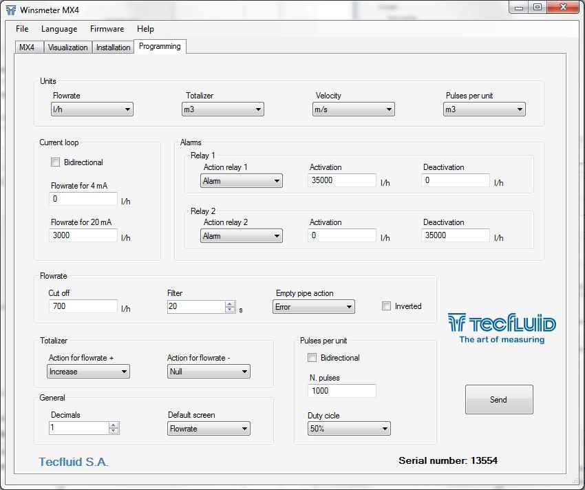
PREFACE
Thank you for choosing the flowmeter series FLOMID from Tecfluid
S.A.
This instruction manual allows the installation and operation of the
electromagnetic sensor FLOMID-FX as well as the configuration
and programming of the electronic converter MX4. It is
recommended to read it before using the equipment.
WARNINGS
This document shall not be copied or disclosed in whole or in
any part by any means, without the written permission of
Tecfluid S.A.
Tecfluid S.A. reserves the right to make changes as deemed
necessary at any time and without notice, in order to improve
the quality and safety, with no obligation to update this manual.
Make sure this manual goes to the end user.
Keep this manual in a place where you can find it when you
need it.
In case of loss, ask for a new manual or download it directly
from our website www.tecfluid.com Downloads section.
Any deviation from the procedures described in this instruction
manual, may cause user safety risks, damage of the unit or
cause errors in the equipment performance.
Do not modify the equipment without permission. Tecfluid S.A.
is not responsible for any problems caused by a change not
allowed. If you need to modify the equipment for any reason,
please contact us in advance.
2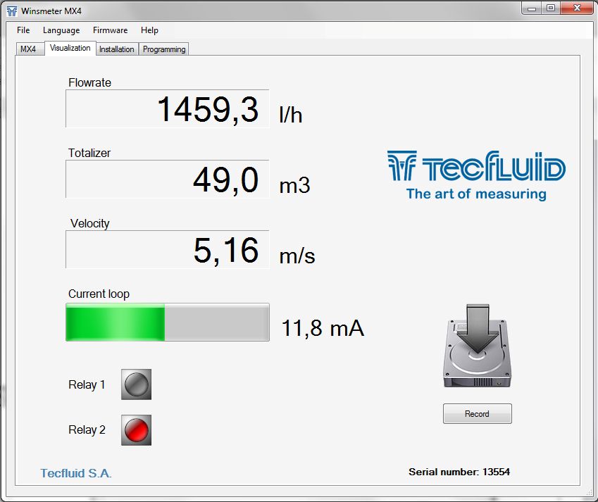
TABLE OF CONTENTS
                                     FLOMID-FX SENSOR
 1   WORKING PRINCIPLE ..........................................................................                6
 2   RECEPTION ...........................................................................................       6
     2.1       Unpacking .................................................................................       6
     2.2       Storage temperatures ..............................................................               6
 3   HANDLING ............................................................................................       7
 4   INSTALLATION ....................................................................................           7
     4.1       Sensor position ........................................................................          8
     4.2       Straight pipe sections ...............................................................            8
               4.2.1       Mixtures ......................................................................       9
     4.3       Valves .......................................................................................    9
     4.4       Pumps ........................................................................................    9
     4.5       Aeration .....................................................................................   10
     4.6       Reduction of DN .......................................................................          10
     4.7       Vibrations ...................................................................................   10
     4.8       Magnetic fields .........................................................................        11
     4.9       Temperature .............................................................................        11
 5   MOUNTING ...........................................................................................       12
     5.1       Parallelism ................................................................................     12
     5.2       Gasket position ........................................................................         12
     5.3       Sensor earth connection ..........................................................               13
     5.4       Tightening torque ......................................................................         14
 6   MAINTENANCE ....................................................................................           14

                                       MX4 CONVERTER
 1   INTRODUCTION ...................................................................................           15
 2   INSTALLATION .....................................................................................         15
     2.1       Sensor connection ...................................................................            15
               2.1.1       Compact converter ....................................................               15
               2.1.2       Remote converter .......................................................             16
     2.2       Electrical connection ................................................................           16
               2.2.1       Power supply wiring ...................................................              17
               2.2.2       Relay output wiring .....................................................            17
               2.2.3       Remote reset input wiring .........................................                  18
               2.2.4       Analog output wiring ...................................................             19
               2.2.5       Pulse output wiring .....................................................            20

                                                     3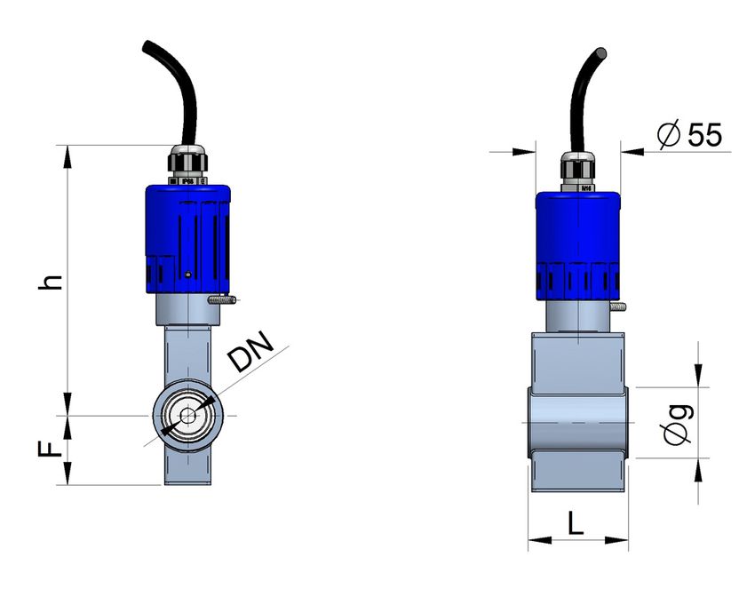
3   REMOTE SENSOR ................................................................................               21
    3.1       Preparing the cable ..................................................................             21
    3.2       Cable installation ......................................................................          23
    3.3       Cable connection to sensor .....................................................                   23
    3.4       Cable connection to converter ................................................                     24
    3.5       Cable specifications ................................................................              25
4   CONVERTER INTERFACE ...................................................................                      26
5   MAIN MENU ...........................................................................................        27
    5.1       Passwords to access the menus .............................................                        27
6   INSTALLATION PARAMETERS ...........................................................                          29
    6.1       Language ..................................................................................        30
    6.2       Sensor factor .............................................................................        30
    6.3       Converter factor ........................................................................          30
    6.4       Nominal diameter ......................................................................            30
    6.5       Diagnosis ..................................................................................       30
              6.5.1        Parameters ..................................................................         31
              6.5.2        Simulator .....................................................................       31
              6.5.3        Mains frequency .........................................................             32
              6.5.4        Coil current .................................................................        32
7   CONVERTER PROGRAMMING ...........................................................                            33
    7.1       Language ..................................................................................        33
    7.2       Units ..........................................................................................   34
    7.3       Flow rate decimals ...................................................................             34
    7.4       Flow rate ....................................................................................     35
              7.4.1        Empty pipe ...................................................................        35
              7.4.2        Cut off ...........................................................................   35
              7.4.3        Reversal flow rate .......................................................            36
              7.4.4        Damping ......................................................................        36
              7.4.5        Offset ...........................................................................    37
    7.5       Outputs .....................................................................................      37
              7.5.1        Relay 1 and relay 2 .....................................................             37
                           7.5.1.1       Alarm ............................................................      38
                           7.5.1.2       Empty pipe ...................................................          38
                           7.5.1.3       Negative flow ................................................          38

                                                     4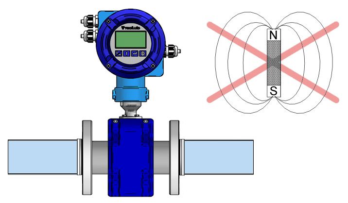
7.5.2        Pulse output ................................................................         38
                             7.5.2.1       Pulse output configuration .........................                    38
                             7.5.2.2       Units .............................................................     39
                             7.5.2.3       Pulses ..........................................................       39
                             7.5.2.4       Duty cycle ....................................................         39
                7.5.3        Analog output ..............................................................          39
                             7.5.3.1       4-20 mA output configuration ...................                        40
                             7.5.3.2       Programming of the 4-20 mA output .........                             40
                             7.5.3.3       Current calibration for 4 and 20 mA .........                           40
      7.6       Working screen .........................................................................           40
      7.7       Totalizer ....................................................................................     41
      7.8       Modbus .....................................................................................       42
8     SERIAL NUMBER .................................................................................              42
9     SOFTWARE VERSION ..........................................................................                  42
10    WORKING SCREEN ..............................................................................                42
11    STARTING CURRENT ..........................................................................                  43
12    MAINTENANCE ....................................................................................             43
      12.1      Fuse ...........................................................................................   43
13    ASSOCIATED SOFTWARE WINSMETER MX4 ..................................                                         44
      13.1      USB cable connection and drivers installation .....................                                44
      13.2      Port connection .........................................................................          45
      13.3      Access to installation and programming ...............................                             46
      13.4      Visualization .............................................................................        48
      13.5      Firmware update ......................................................................             49
14    TECHNICAL CHARACTERISTICS .......................................................                            50
15    DIMENSIONS ........................................................................................          52
16    TROUBLESHOOTING ...........................................................................                  62
ANNEX A Flow rate diagram ......................................................................                   63

                                                      5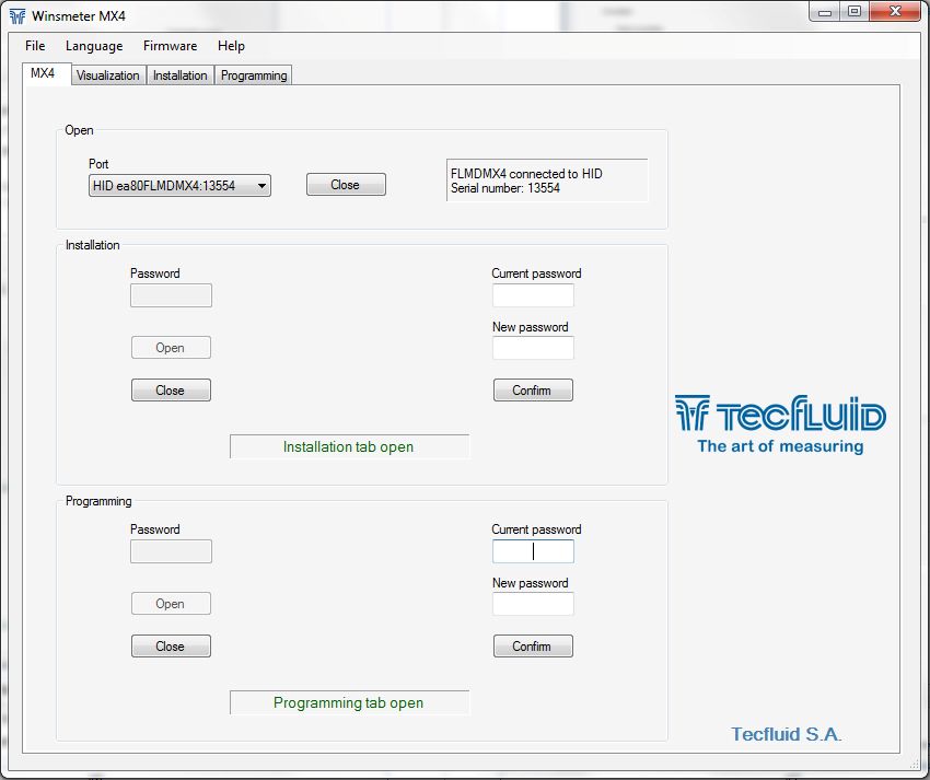
WORKING PRINCIPLE

    1     WORKING PRINCIPLE
          The FLOMID electromagnetic flowmeters are based on Faraday’s induction law.

1         When an electrically conductive liquid flows through a magnetic field, perpendicular to the
          flow direction, it induces a voltage Vm proportional to the liquid velocity.
          Two electrodes in contact with the liquid and positioned perpendicularly to the magnetic

2         field, sense this voltage Vm.

                                               V = B·vm·D
                                 Where:

                                 V    = Measured voltage in the electrodes
                                 B    = Magnetic field
                                 vm   = Average liquid velocity
                                 D    = Pipe diameter

    2     RECEPTION
          The FLOMID electromagnetic flowmeters are supplied conveniently packaged for
          transportation together with their instruction manual for installation and operation.
          All the flowmeters have been verified in our calibration rigs to obtain the Fc factor for each
          sensor.
    2.1   Unpacking
          Unpack the instrument carefully, removing any remains of the packing from the inside of
          the sensor. Do not remove the grease from the neck that couples to the electronics
          housing.
    2.2   Storage temperatures
          Sensors linings of :         PTFE and PVDF       -20ºC ...... +60ºC
                                       PP and EBONITE       -5ºC ...... +50ºC

                                                       6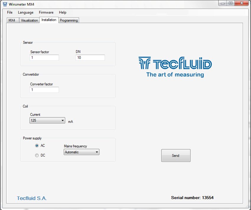
HANDLING

3   HANDLING
    It should always be done with care and without knocks.
    The large diameter sensors have rings for holding the elevation elements. If the flowmeter
    is held using slings, these should hold on the sensor and not on the electronics housing
    (see drawing).

                                                                                                 3
                                                                                                 4

4   INSTALLATION
    This should be made in a point that guarantees that the pipe is always completely full.
    Avoid high points of the pipes where air pockets usually form, or pipes with falling flow
    where vacuums can form.
    Partially full pipes can produce important reading errors.
    Flow rate measurement with open discharge makes it necessary to install the flowmeter in
    a pipe section with a siphon which avoids stagnation of air in the sensor.

                                              7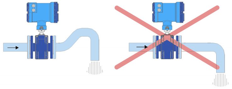
INSTALLATION

    4.1   Sensor position
          The most adequate position is with the electrodes in a horizontal plane. In this way,
          deposits of particles on the electrodes are avoided.

4

    4.2   Straight pipe sections
          They are necessary before and after the sensor. The minimum distances are the
          following:
                   Upstream   5 DN
                   Downstream 3 DN
          In installations with turbulent flow it may be necessary to increase these distances.

                                                   8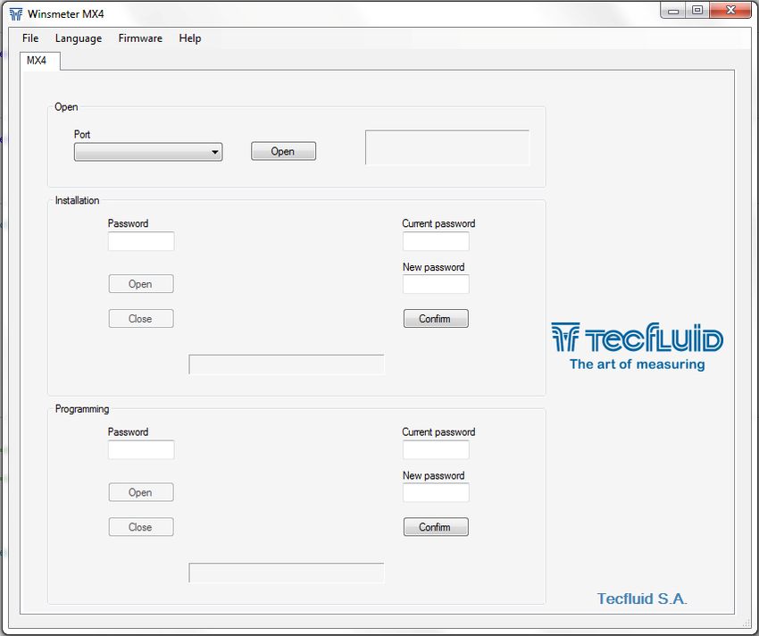
INSTALLATION

4.2.1   Mixtures
        If liquids of different conductivities are mixed it is necessary to install the sensor a
        minimum of 30 DN from the point of mixture in order to obtain a uniform conductivity of the
        liquid and stabilize the readings.
        If this distance is shorter, readings may be unstable.

                                                                                                      4

4.3     Valves
        Control valves or shut-off valves should always be installed downstream from the sensor
        to assure that the pipe is always full of liquid.

4.4     Pumps
        Pumps should be mounted upstream from the sensor to avoid the suction of the pump
        (vacuum) that could damage the sensor liner.

                                                9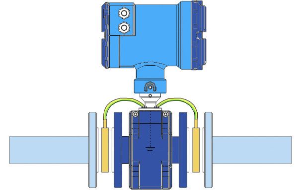
INSTALLATION

    4.5   Aeration
          If there is a point where the difference in level is higher than 5 m an air inlet valve should
          be installed after the sensor to avoid a vacuum effect that could damage the sensor liner.

4

    4.6   Reduction of DN
          In installations where, due to reasons of the flow rate to be measured, a sensor of a
          smaller DN than the pipe DN must be mounted, the reduction must be done with an angle
          smaller than 4º to avoid turbulences that can give false readings.
          If the angle cannot be so small, straight pipe sections indicated in 4.2 point must be kept.

    4.7   Vibrations
          Vibrations of the pipes should be avoided by anchoring the pipe before and after the
          sensor.
          The vibration level should be less than 2.2 g in the range of 20 -150 Hz according to IEC
          068-2-34.

                                                   10
INSTALLATION
4
4.8 Magnetic fields
Strong magnetic fields close to the sensor should be avoided.
4.9 Temperature
In open air installations it is recommended to install a protection to avoid direct sun light
on the flowmeter.
With thermally insulated pipes DO NOT insulate the sensor. High temperatures can
damage it.
The maximum liquid temperatures are shown on page 50.
11INSTALLATION
5 MOUNTING
5.1 Parallelism
5
The maximum parallelism error must be less than 0.5 mm (Lmax—Lmin ≤ 0.5 mm).
5.2 Gasket position
For the wafer mounted sensors, in order to avoid leakage into the inside of the sensor one
must make sure that the rubber gasket (A) of the figure below is fitted into the stainless
steel ring so that it will be pressed directly on the plastic liner.
If the rubber gasket seals against the stainless steel ring then the liquid pressure will force
liquid into the interior of the sensor causing irreparable damage.
The standard material for the supplied gasket is NBR.
The sensors with connections different to wafer are supplied without gaskets.
12INSTALLATION
5.3 Sensor earth connection
To obtain correct operation the sensor should have its functional earth connected to a
point that is in direct contact with the liquid whose flow rate wants to be measured.
The earth cables should assure a good electrical contact. To obtain this, they should be
well screwed down and with a good contact on both sides of the sensor. It is important to
eliminate paint or coverings that act as insulation of the connection.
The functional earth connection should be used exclusively for the sensor given that
parasitic signals caused by other electrical equipment connected to this earth can cause
malfunction of the sensor.
In the case that there are high voltage differences between different earth points, this will
cause currents that may give problems in the readings (empty pipe indication). In these
cases, do not connect the functional earth to the protective earth of the mains.
The connection of the functional earth should be made as follows:
a) In the case of metallic pipes without internal lining connect the earth cables to the
counter flanges.
5
b) In the case of metallic pipes with internal lining or plastic pipes, connect the earth
cables to the earthing disks, supplied on request.
The earthing disks are necessary when the installation is with plastic pipes or metallic
pipes with an internal insulating lining (PTFE, PVDF, PP EBONITE etc.).
13INSTALLATION
Earthing disks are supplied in two versions:
METALLIC, disk in stainless steel EN 1.4404 (SS 316L), for liquids compatible with this
material.
PLASTIC, with an electrode to make the contact with the liquid. The materials (plastic and
metal) depend on the working liquid.
5
5.4 Tightening torque
The tightening torque for the flange bolts should not exceed 32 Nm for working pressures
of 16 bar maximum.
This tightening torque should be applied to sandwich mounting (Flomid-0FX) and also to
flange mounting sensors (FLOMID-2FX) for the same working pressure of 16 bar.
The maximum tightening torque varies in function of the nominal pressure (PN) of the
sensor.
The tightening of the bolts should be uniform, following the sequence shown in the
drawings and depending on the number of flange bolts.
6 MAINTENANCE
It is recommended to clean the electrodes in installations where incrustations or
appreciable sedimentations can occur.
Cleaning can be done using liquid detergents and medium hard brushes.
14INTRODUCTION
MX4 CONVERTER
1 INTRODUCTION
The MX4 converter unit can be used with the different FLOMID and FLOMAT series of
electromagnetic flow sensors. The electronic circuit is based on the most advanced
technology in digital signal processing, in order to obtain accurate and reliable
1
measurements.
The device provides the following features:
Coil excitation by means of pulsed signal to obtain a negligible zero offset.
Pulse and current output proportional to the flow rate and user programmable.
Relay outputs user programmable as flow rate alarm or status.
Local and remote mounting.
Easy exchange with other sensors.
Graphic display with intuitive menus.
Adjustable front cover in order to make display reading easier, depending on
installation.
2 INSTALLATION
2.1 Sensor connection
2.1.1 Compact converter
The converter provides two
cables to be connected to the
sensor. Once connected,
slide the converter along the
sensor neck until the stop.
Tight the two fixing screws.
15INSTALLATION OF THE ELECTRONIC CONVERTER
2.1.2 Remote converter
One of the ends of the cable has a header and two wires, to connect them to the sensor.
The connection is as explained in point 2.1.1.
The other end has to be connected to the converter, and has five wires. The cable must
be passed through the cable gland and the connection for each wire is explained in
chapter 3.
2 2.2 Electrical connection
For the electrical installation, the MX4 converter has two terminal strips. To help in the
wiring of the equipment, the description of the terminals is marked on a label in the rear
cover of the device.
For the electrical installation it is recommended to use multiple conductor cables with
individual cable sections in the order of 0.25 to 0.5 mm2 in order to make it easier to
connect. It is better to maintain the cables with mains voltage (power supply) separated
from the cables with low level signals (4-20 mA, etc.).
Before starting the installation, check that the cable glands are the right size for the cables
to be used. This will guarantee the instrument will stay watertight. The cable glands used
are for cables with outside diameters between 3.5 mm and 10 mm
To connect the cables, peel the outside insulation to free the inner cables. It is
recommended to put a terminal at the ends of the wires to avoid loose ends. Pass the
cables through the cable glands and screw down in the corresponding positions of the
terminal strip. Once the wiring is finished make sure that the cables are well gripped by
the cable glands to maintain the degree of protection.
Incorrect installation of the cable gland or inadequate cable placement can cause
irreparable damage to the converter.
IMPORTANT NOTE: In order to comply with the electrical safety requirements as
per EN-61010-1 (IEC 1010-1), the installation of the equipment must take into account the
following:
A mains switch must be provided to disconnect the equipment. This switch must
be marked as the disconnecting device for the equipment and be within easy
reach of the operator.
The mains supply must have an earth line.
The housing must not be opened when the instrument has mains supply
connected.
IMPORTANT NOTE: To ensure smooth operation of the equipment, it is
recommended to make the connection paying attention to the following points:
For the output signals, use shielded cable when possible.
Keep the cables away from strong sources of noise.
16INSTALLATION OF THE ELECTRONIC CONVERTER
2.2.1 Power supply wiring
Before starting the installation of the equipment, check that the supply voltage available is
the same as marked on the label of the converter.
2
Terminal Power supply AC Power supply DC
8 Earth NC
9 Neutral -
10 Phase +
It is very important to connect the mains earth to the instruments with AC power supply
due to the presence of a mains filter inside the converter that uses this connection.
2.2.2 Relay output wiring
17INSTALLATION OF THE ELECTRONIC CONVERTER
Terminal Description Relay
6 Normally Open Relay 1
5 Common Relay 1
4 Normally Open Relay 2
3 Common Relay 2
2 The relay outputs provide relays with potential free contacts (see characteristics in page
50).
The status of the relay contacts corresponds to the relay at rest.
The relay contacts are not protected in any way, and therefore they must be installed
externally as required in the application, taking into account the limitations of the
characteristics of such contacts. In the case of having inductive loads, and to extend the
working life of the relay contacts, it is recommended to use overvoltage protection (VDR
for AC and diodes for DC loads). In all cases a fuse or some kind of protection against
short circuits, should always be provided according to the needs of the intended load.
2.2.3 Remote reset input wiring
18INSTALLATION OF THE ELECTRONIC CONVERTER
Terminal
1 Contact
2 Contact
These terminals correspond to an input that resets the value of the totalizer. A potential
free normally open push button can be connected. The push button contact must be a
good quality snap action switch to guarantee correct working at low voltages and reduce
2.2.4
contact bounce effects.
Analog output wiring 2
Terminal
11 mA (positive, active output)
12 mA
13 mA (negative, passive output)
The analog output is galvanically isolated. It can be either active (which means that the
receiving device must be passive) or passive (which means that the receiver must supply
the power for the current loop). It is recommended to use a receptor with an input
resistance of less than 700 Ω to guarantee correct operation.
The configuration of the analog output mode (active or passive) is done by means of the
connection to the terminal strip. For active mode, terminals 11 and 12 are connected. For
passive mode, terminals 12 and 13 are connected.
NOTE: The analog output has protection against reversed polarity. Due to another
protection against over voltages, if a loop supply voltage of more than 32 V is connected
the equipment may be damaged.
19INSTALLATION OF THE ELECTRONIC CONVERTER
Active output
2 Passive output
2.2.5 Pulse output wiring
Terminal
14 Collector
15 Emitter
The pulse output is opto-isolated. The terminals are the collector and emitter of a NPN
bipolar transistor.
In the case of using inductive loads, in order to protect the output transistor, the use of
free wheeling diodes is required.
Coil
20REMOTE SENSOR
Example. Connection with the load at the collector
LOAD
3
Example. Connection with the load at the emitter
LOAD
3 REMOTE SENSOR
When an installation requires that the electromagnetic sensor is separated from the
control unit, the union between these two elements must be made by means of an
interconnection cable.
Normally, these cables are supplied by Tecfluid S.A., already prepared for their direct
connection to the sensor and the converter.
Important: The interconnection cable between the sensor and the converter must
always be a single piece, without any kind of joint.
In the event of having to repair a broken cable at one of its ends, it should be cut at the
breakage point and reworked for the connection at that point.
3.1 Preparing the cable
The ends of the cable should be prepared as shown in the drawing on next page. Special
care should be taken to avoid possible short circuits between the shields. The point at
which the shields are cut refers to the aluminium shields.
Electronics side
At the electronic unit’s end, the ends of the cables should be striped at about 5 mm and
then tined. Pair 1 (Red & Black) is for the excitation coils and Pair 2 (White & Black) is for
the electrodes.
Sensor side
Pass the sensor side end through the cable gland of the sensor connector and then
connect the cables of this end to the IDC connectors as shown in the following drawing.
(the unión between terminals 2 and 4 in Pair 2 must be taken into account).
21REMOTE SENSOR
3
22REMOTE SENSOR
3.2 Cable installation
The following points must be taken into account:
The cable should be installed in a conduit or should be securely fixed, given that
movements of the cable can induce reading errors.
The cable should be placed as far as possible from sources of electrical noise such as
switching gear and electrical machines.
The maximum length of the connection cable depends on the fluid conductivity. For
3.3
liquids with a conductivity higher than 500µS/cm cable length can be up to 150 m.
Cable connection to sensor
3
For the sensor connection, first loosen the cable gland to allow the cable to slide in it.
Make sure that the two fixing screws of the cover do not protrude inside the cover (this
avoids damaging the o-ring of the sensor neck).
Apply a few Vaseline on the sensor neck to aid inserting in the cover, specially on the o-
rings.
Connector cover
Male connectors
Fixing screws
Sensor neck
23REMOTE SENSOR
Connect the two cable connectors in their corresponding male connectors on the sensor,
mating the bumps in the guide of the male connectors.
Slide the cover on the sensor neck until it meets its stop.
Tighten the two fixing screws to anchor the cover.
Tighten the cable gland to guarantee water tightness.
3.4 Cable connection to converter
3
Terminal
16 Top coil (red cable)
17 Bottom coil (black cable)
18 Rear electrode (white cable)
19 Ground (shield)
20 Front electrode (black cable)
So that the flow direction shown in the instrument matches the actual direction, please take into
account the cables colour scheme according to previous figure.
24REMOTE SENSOR
3.5 Cable specifications
Model: CERVITRONIC PAR-POS Code 04754502
Construction
Conductor: Annealed electrolytic copper, tinned
As Norm: UNE 21064
Isolator: Polyolefin (PE - Solid)
Composition: By pars
Par shield: Tape Al/Pet + Drain Cu Sn
Cover :
All over shield:
100 % Physical
Tape Al/Pet + Drain Cu Sn
3
Cover: 100 % Physical
Exterior cover: PVC
Colour: Black
Electrical characteristics
Working Voltage: 250 V
Testing Voltage: 1000 V
Electrical resistance: ≤ 52,2 Ω/km
Capacity: C* / C** 90-170 pF/m
C* capacity between conductors
C** capacity between one conductor and the rest connected to the shields
Physical characteristics
External diameter: 6,6 mm
Bending radius: 66 mm
Working temperature: -5... +70ºC
Fire risk: Does not propagate flame as per Norm IEC 60332-1 and EN 50265
Section: 0,34 mm2
Weight: 51 kg/km
Cable section
1 PVC cover
2 External shield wire
3 Insulating film
4 Pair 1/2 shield wire
5 PVC insulation
6 Pair 1/2 conductor
7 Aluminium shield
25CONVERTER INTERFACE
4 CONVERTER INTERFACE
The MX4 converter has a graphic LCD and a keyboard with 4 push buttons.
The keyboard has four numeric keys to introduce the values of installation and
programming. Two of these keys are used also as cursors.
4 The following figure shows the functionality of the converter keys.
(Down / Left) To switch between flow
rate, totalizer and fluid velocity screens.
To change to the digit on the left.
Into the menu, to scroll down.
(Up) To switch between flow rate,
totalizer and fluid velocity screens. To
increase the digit.
Into the menu, to scroll up.
(Enter) To validate the data.
To enter into installation and
programming modes of the converter.
To exit from an informative text.
(Escape) To return to the previous
menu. To exit from a screen without
validating data.
26MAIN MENU
5 MAIN MENU
To access the main menu of the converter, press the key (Enter). The following screen
appears:
Number of menu items
Selected item
The "Installation" option allows the basic configuration of the instrument, as explained in
Chapter 6 of this manual.
The "Programming" option allows to program all parameters of the converter, as
explained in Chapter 7 of this manual.
From the "Reset totalizer" option, the user can return the totalizer to zero. When exiting
5
the menu, the totalizer will begin to accumulate again.
Note: The “ Reset totalizer” operation requires the program password input (see
point 5.1).
The options "Software Version" and "Serial Number" are informative and are discussed in
Chapters 8 and 9 of this manual.
5.1 Passwords to access the menus
The password for the installation menu may be different from the password for the
program menu.
By default, the equipment is factory configured with the password disabled.
If you want to change any of these passwords, you must enter the corresponding menu
and once inside, access the submenu "Password".
To change the access password of To change the access password of
the installation menu, select the programming menu, select
"Installation" on the main menu and "Programming" in the main menu
then "Password". and then "Password".
27MAIN MENU
When the "Password" option is selected, a screen that indicates the password status for
this menu appears.
Selecting “enable”, the screen to enter the new password appears.
5
Once entered, the new password is asked again to avoid possible inadvertent error.
If the re-entered password does not match the first one, the following error message
appears and the process should be carried out again.
If both passwords match, the following information message is displayed:
28INSTALLATION PARAMETERS
If the password needs to be changed or disabled, the procedure is the same. Once
entered the "Password" menu, the following screen appears:
If change is selected, the equipment will ask for a password again. If Disable is selected,
the following message will appear:
6
6 INSTALLATION PARAMETERS
Power on the electronic converter with the voltage indicated on the label.
Press the (Enter) key in order to enter the main menu.
With the keys (Down / Left) and (Up), select “Installation”, and then validate with the key
(Enter).
In order to access to the Installation menu, a password must be entered. When accessing
the first time, the default password is 0123. For more details about the password, see
paragraph 5.1, page 27.
Once the password is entered, and after pressing the key (Enter), the first screen allows
to choose between the different options of the installation menu.
29INSTALLATION PARAMETERS
6.1 Language
You can choose the language in which all the menus will be displayed.
6.2 Sensor factor
In this screen the sensor factor is shown. It should coincide with the Fc parameter on the
sensor label.
6 6.3 Converter factor
The electronic converter factor is shown. It should coincide with the Fe parameter on the
converter label.
6.4 Nominal diameter
The value of the nominal diameter is always the internal diameter of the sensor.
6.5 Diagnosis
When the flowmeter is not working properly, it can be useful to test some parts of the
instrument in order to locate the problem.
In this section a list with two possible options appears.
30INSTALLATION PARAMETERS
6.5.1 Parameters
This screen allows the diagnosis of the coil current, the differential voltage on the sensor
electrodes, and the conductivity of the liquid.
In the first row, a possible damage of the sensor coils can be detected. If there is a
symbol Ѵ on this row, it means that the coils do not have any damage. If the symbol is X
it means that the coils are damaged. In this case, please contact your distributor.
The second row shows if the conductivity of the liquid is high enough for the instrument to
perform the measurement process.
The conductivity of the liquid should always be higher than 20 uS / cm .
The third row shows the differential voltage value on the electrodes (Vdif).
This voltage appears in some cases where chemical reactions are created on the surface
of the electrodes.
6
While this value does not exceed 0.5 V the flowmeter can work properly. If the value is
higher, there is no guarantee that the flow reading is correct. In this case, please contact
your distributor.
6.5.2 Simulator
With this diagnosis an electronic fault in the measuring circuit can be checked.
Before checking, disconnect the electrodes from the converter. To do this, if the converter
is compact mounted, remove the electrodes IDC connector shown in the figure on page
15 (5-pin cable). If the converter is remote mounted, remove the electrodes wires
(terminals 18, 19 and 20) of the terminal strip on the back (p. 24)
Pressing Enter a screen indicating a simulated speed of the liquid is shown. If the circuit is
working properly the displayed value will be between 4 and 6 m/s.
To come back to the main menu, connect the electrodes cable again and press Escape
key.
31INSTALLATION PARAMETERS
Press again the Escape key until the working screen.
6.5.3 Mains frequency
If the power supply of the converter is AC, the following screen will appear:
6 Normally "Automatic" should be selected. In this case, the computer automatically detects
the frequency of the mains and thus uses the most appropriate coil excitation to eliminate
noise from the mains.
The detected frequency can be shown in the screen that appears when you select the
automatic mode.
If manual mode is selected, the mains frequency can be chosen between the two most
prevalent in all countries, 50 and 60 Hz
If the power supply of the converter is DC, this screen appears directly.
6.5.4 Coil current
In normal situations it is not necessary to change the coil current selected in the
equipment by default.
NOTE: So that this change is effective, several jumpers inside the instrument need
to be changed. In case that a different coil current must be used, please contact your
distributor.
32CONVERTER PROGRAMMING
7 CONVERTER PROGRAMMING
By programming the converter the visualization and the outputs of the instrument can be
configured.
Turn on the converter and press (Enter) to enter the main menu. The following screen
appears
With the keys (Down / Left) and (Up), select Programming, and then validate with the key
(Enter).
If the converter has the password option enabled, a password must be entered. For more
details about the password,, see section 5.1 on page 27.
7
Once the password is entered, the first screen allows to choose between the different
programming options.
7.1 Language
You can choose the language in which all the menus will be displayed.
33CONVERTER PROGRAMMING
7.2 Units
In this screen the units for the liquid velocity, the flow rate and the totalizer can be chosen
independently.
7
7.3 Flow rate decimals
In this screen the number of decimals for the flow rate indication can be selected.
To select the number of decimals it must be taken into account that the instrument has 5
digits for flow rate indication. If two decimals have been selected, these will be seen whilst
the flow rate is not higher than 999.99. Above this value the indication will automatically
change to one decimal, and when the flow rate is higher than 9999.9 the indication will be
done without decimals.
If one decimal is selected, the flow rate indication will have a maximum of one decimal
until 9999.9. Above this value the indication will be done without decimals.
If indication without decimals is selected, the flow rate will always be shown without
decimals.
For the selection of the flow rate units and the number of decimals it must be taken into
account that an indication with an excess of decimals may give the sensation of instability
of the reading. As a general rule it can be considered that the reading should not have
more than a total of 5 digits (integer + decimals).
34CONVERTER PROGRAMMING
7.4 Flow rate
This screen displays a submenu to modify different aspects related to flow reading, such
as empty pipe detection, cut off, reversal flow, filtering and offset.
7.4.1 Empty pipe
Detection can be programmed in two different ways.
In the event that Error is selected, when the converter detects empty pipe, it will display
7
the following error message instead of readings.
If Warning is selected, in the event of detection of empty pipe, the converter will keep
working normally and the symbol “!” will appear next to the measured value, indicating
that the reading is not reliable.
7.4.2 Cut off
A cut off flow rate can be programmed, that means, the flow rate below which the flow
rate indication will be zero. This can avoid reading errors in the lower zone of the scale.
The maximum allowed value for the cut off is the equivalent to a liquid velocity of 1 m/s.
35CONVERTER PROGRAMMING
7.4.3 Reversal flow rate
The MX4 is a bi-directional converter. The flow rate changes its sign automatically when
the flow is reversed. If after the converter has been installed it is necessary to reverse the
flow rate sign, in this screen it can be done by selecting the option “REVERSAL– Yes”.
7 7.4.4 Damping
El MX4 converter has an adaptive filter (damping) to provide stable flow rate and analog
output readings in the presence of continuous flow rate fluctuations.
The configuration of this filter can be very useful in the cases where the flow rate readings
have some instability (due to air bubbles, solids in suspension, etc.
Only the flow rate indication of the display and the analog output are affected by the filter.
The relay output and the totalizer act according to the instant flow rate. Selecting a filter
with a longer or shorter integration time will provide more or less stable readings and will
also affect the response time to small variations of flow rate.
The integration time is selected in seconds, with a minimum value of 0 and a maximum
value of 40 seconds. For example, with an integration time of 15 seconds, the display will
indicate the flow rate reading of the average flow rate over the last 15 seconds from the last
update of the display. This does not mean that the display is refreshing its data every 15
seconds. The display shows a new value several times per second, indicating an average
of the flow rate values of the last 15 seconds.
When there is a sudden variation of the flow rate then the filter should react as fast as
possible to give a correct reading of the new value. For this, the filter controls the deviation
of the instant flow rate with respect to a reference for each reading. If this deviation
exceeds the 10%, the filter will stop acting, indicating the instant value, and will start again
the filtering process.
36CONVERTER PROGRAMMING
7.4.5 Offset
In order to obtain a perfect linearization of the instrument, it is recommended to make an
adjustment of the zero offset each time an installation is performed.
The flow rate must be zero, that is, the liquid inside the pipe where the flowmeter is
installed should be completely stopped. Furthermore, a completely full pipe is necessary
in order to make an effective adjustment.
When the option Offset is selected, the following screen is shown:
When the flow rate is stable, press the key (Enter) and the instrument will save the value.
7
7.5 Outputs
This screen allows to program the four outputs of the instrument: Relay 1, Relay 2, pulses
and analog output (4-20 mA).
7.5.1 Relay 1 and relay 2
By selecting one of the two relay outputs, next screen appears with the options which
allow to assign the relay to a function.
37CONVERTER PROGRAMMING
7.5.1.1 Alarm
If Alarm is selected, we have access to program the flow rate at which the relays will
change its status and to the level of hysteresis. By level of hysteresis we understand the
difference between activation and deactivation of the output. To avoid that an alarm
output is continuously moving from activate to deactivate status, we must program the
points of connection and disconnection.
Example
If the activation point is programmed to 100 m3/h and the deactivation point is
programmed to 90 m3/h, when the flow rate is zero the output will be deactivated. When
the flow rate reaches a value of 100 m3/h the output will be activated until the level falls
below 90 m3/h.
If we program an activation point of 90 m3/h and a deactivation point of 100 m3/h, when
the level is zero the output will be activated. When the flow rate reaches a value of 100
7 m3/h the output will be deactivated until the flow rate falls below 90 m3/h.
7.5.1.2 Empty pipe
In this case, the relay will change its status when the flowmeter detects empty pipe.
7.5.1.3 Negative flow
The relay will change its status when the flow rate changes its sign.
7.5.2 Pulse output
This output allows to connect the converter to a PLC or remote totalizer. The number of
pulses per unit of volume can be programmed. The following parameters can be selected.
7.5.2.1 Pulse output configuration
It allows to choose between unidirectional and bidirectional.
38CONVERTER PROGRAMMING
If “Unidirectional” is chosen, the output will give pulses proportional to flow rate when the
flow rate is positive, and will not give them when the flow rate is negative.
If “Bidirectional” is chosen, the output will give pulses proportional to flow rate in both flow
directions.
7.5.2.2 Units
First volume units for which we want to get a number of pulses are selected.
7.5.2.3 Pulses
Then the pulses per unit of volume that we will obtain at the output are selected .
7
7.5.2.4 Duty Cycle
With the duty cycle width or percentage of time the pulse will be active during each cycle
can be determined
Active pulse is when the NPN transistor at the output (see 2.2.5) is ON.
7.5.3 Analog output
The flow rate corresponding to 4 mA and 20 mA can be programmed and the calibration
for these two values can be made as well.
39CONVERTER PROGRAMMING
7.5.3.1 4-20 mA output configuration
It allows to choose between unidirectional and bidirectional.
If “Unidirectional” is chosen, the analog output will have a value proportional to the flow
rate when positive, and it will provide always 4 mA when negative.
If “Bidirectional” is chosen, the analog output will have a value proportional to the flow rate
both for positive and negative values.
7.5.3.2 Programming of the 4-20 mA output
Flow rate values equivalent to each current are entered directly.
7
Programming a flow rate value for 20 mA higher than the one for 4 mA, the loop current
changes from 4 to 20 mA as the flow increases.
Otherwise, programming a flow rate value for 20 mA lower than the one for 4 mA, the
current loop will change from 20 to 4 mA as the flow increases.
7.5.3.3 Current calibration for 4 and 20 mA
The MX4 converter is delivered with the current output already calibrated. If you want to
correct a derive of the 4 or 20 mA current values because they do not coincide with the
ammeter used, it can be done by pressing the keys (Down / Left) and (Up) to increase or
decrease the current respectively in each case. The values shown on the screen are
reference levels. When one of this data is confirmed, the MX4 will take the current value
shown on the ammeter as a reference.
Before making a current calibration, be sure that the ammeter used for that is showing the
real measure.
7.6 Default screen
Flow rate, totalizer, liquid velocity or flow rate and totalizer screens can be programmed
as a default. Thus, the converter presents this screen when a power failure occurs or
when returning from the installation or programming menu.
40CONVERTER PROGRAMMING
7.7 Totalizer
In this screen you can configure the totalizer operation mode depending on the flow
direction. Thus, the value indicated by the totalizer will always be true regardless of the
application where the flowmeter is installed.
The first screen after selecting “Totalizer” is the following:
7
In this screen you can choose the flow direction for which you want to configure the action
that the totalizer will do.
Positive flow is defined as the one that appears unsigned on the default screen, and
negative flow the one that appears with a — sign on the default screen.
Once the flow rate direction is chosen, a screen with the different actions is shown:
If "Null" is selected, the totalizer remains unchanged. If "Increase" is selected, the totalizer
will add the amount of fluid passing through the flowmeter, and if you select "Decrease",
the totalizer will subtract that amount.
Examples:
a) Installation in which for a time the product flows through the pipe and after that a
cleaning process in reverse direction is performed. The programming will be:
Positive flow rate action: Increase
Negative flow rate action: Null
b) Installation in which for a time the product flows through the pipe to a tank, and
after that a quantity of the product comes back in the opposite direction. The
programming will be:
Positive flow rate action: Increase
Negative flow rate action: Decrease
The totalizer will indicate the volume of product that there is in the tank.
c) Installation in which for a time a first product flows through the pipe, and after that
a second product flows in the opposite direction. The programming will be:
41CONVERTER PROGRAMMING
Positive flow rate action: Increase
Negative flow rate action: Increase
The totalizer will indicate the volume corresponding to the sum of both products.
Note: To reset the totalizer, go to chapter 5 (page 27).
7.8 Modbus
This option is only implemented in some devices.
It allows to configure the needed parameters to establish a Modbus RTU communication
with the instrument.
Detailed information on this point could be found in the R-IT-MX4COM instructions
manual, that can be downloaded from Tecfluid S.A. website.
8 SERIAL NUMBER
In this section the converter serial number is shown.
9 SOFTWARE VERSION
8 From the main menu, if “Software version” is selected, the screen will show this data and
the corresponding date.
9
10
10 WORKING SCREEN
When exiting the menu, the display shows the default screen. To scroll between the three
operating screens, press the key (Down / Left) or (Up).
42DEFAULT SCREEN
11 STARTING CURRENT
It may happen that the chosen power supply can not provide the required current for the
equipment to operate properly. In this case an information message will appear indicating
this situation.
11
12 MAINTENANCE 12
No special maintenance is required.
For cleaning, a humid cloth can be used, and if necessary with a little neutral soap.
Solvents or other aggressive liquids which could damage the housing material should not
be used.
12.1 Fuse
In the event that the fuse blows, this should be replaced with a slow blow “T” fuse, size
Ø5 x 20 mm and value 250 mA.
43ASSOCIATED SOFTWARE WINSMETER MX4
13 ASSOCIATED SOFTWARE WINSMETER MX4
Most of the steps in the preceding paragraphs can be done by means of the device
associated software Winsmeter MX4, which allows working in a more comfortable and
intuitive way.
Such software can be downloaded from the “Downloads” section of the Tecfluid S.A.
website.
13.1 USB cable connection and drivers installation
Extract the files from the winsmeterMX4.zip to a new system folder.
Execute the Setup.exe file and follow the steps for the installation.
In order to connect the converter to a computer an USB cable is required. This cable is type
A at one end and type B at the other, and it is readily available on the market.
The ends of the cables.can be seen in the picture.
The first step to do the connection is to open the rear cover of the electronic converter.
13
44ASSOCIATED SOFTWARE WINSMETER MX4
The USB connector is located below the right terminal strip (see figure on the previous
page).
Connect the USB cable at one end to the converter and at the other to the computer where
the software is installed.
Power on the electronic converter.
Execute the program WinsmeterMX4 following the sequence Start – Programs – Tecfluid
S.A. - WinsmeterMX4.
13.2 Port connection
In the "Port" section, choose the appropriate port for the converter. This will appear with the
name of the port followed by MX4 and its serial number. Then click "Open".
13
Once the port is open, the button "Open" in the "Installation" and “Programming” sections
activates.
45ASSOCIATED SOFTWARE WINSMETER MX4
13.3 Access to installation and programming
In order to change the data contained in the "Install" tab, you must enter a password.
The default password is install, and it can be changed using the boxes on the right of the
"Installation" section.
Likewise, to change the data contained in the "Programming" tab it is necessary to enter the
password which by default is program. This can be changed using the boxes on the right of
the "Programming" section.
13
Once the password is written, press "Enter" or "Open", and the installation or programming
tab will open. At the bottom of each section the text "Installation tab open" or "Programming
tab open" will be displayed
To enter the Installation window, just click the corresponding tab.
46ASSOCIATED SOFTWARE WINSMETER MX4
In the installation window the parameters that adapts the converter to a sensor and to a
determinated installation can be configured.
To transfer data to the MX4 converter, press the “Send” button. The message "Saving
program" will appear for two seconds in the converter screen. The installation data will be
stored in the memory of the converter.
13
47ASSOCIATED SOFTWARE WINSMETER MX4
Likewise, to enter into the programming window, just click the corresponding tab.
Changing the parameters of this screen, (see previous page) you can program the different
functions of the equipment.
As in the previous paragraph, to program this data to the MX4 converter, press the “Send”
button. The message "Saving program" will appear for two seconds in the converter screen.
The programming data will be stored in the memory of the converter.
13.4 Visualization
When the communication with the computer port is established (see section 12.2), the tab
"Visualization" opens. This tab lets you view real-time flow rate, totalizer and velocity values,
as well as the current value of the analog output and the status of the relay outputs.
It is an intuitive tool to verify that the instrument has been installed and programmed
correctly.
By means of the "Record" button, you can store data in different computer files, which can
then be processed by other software.
13
48ASSOCIATED SOFTWARE WINSMETER MX4
13.5 Firmware updates
New firmware updates can be published in the website. These updates contain
improvements or bug fixes that make the equipment operates at best conditions.
The updates can be downloaded from the following link of Tecfluid S.A. website
www.tecfluid.es/productos/descargas/software/MX4.hex
To update the equipment, go to menu “Firmware” - “Update”, and a screen with the button
“File” will appear. Pressing this button system can be accessed. The downloaded file has to
be searched there.
Once the file is selected, press the “Program” button. A message “Programming device” will
appear.
The process takes about 90 seconds, after which the message “Device programmed” will
appear.
13
From this moment, the converter MX4 already has the new version of Firmware.
49TECHNICAL CHARACTERISTICS
14 TECHNICAL CHARACTERISTICS
Accuracy
reading value for v > 0,4 m/s
reading value for v < 0,4 m/s
Repeatability
± 0.1% reading value
Velocity range
0.1 ...10 m/s
Temperature
Process temperature:
PP: -10 ºC … 80 ºC
PTFE, PVDF: -20 ºC … 120 ºC
Ebonite: -20 ºC … 90 ºC
Ambient temperature range: -20 ... +60 ºC
Minimum conductivity
20 µS/cm
Power supply
90 ... 265 VAC 50, 60 Hz Power consumption: ≤ 5 VA
12 ... 48 VDC Power consumption: ≤ 5 W
Analog output
4-20 mA. Active or passive. galvanically isolated from the power supply.
Pulse output
Optoisolated. NPN bipolar transistor. Vmax: 30 VDC. Imax: 30 mA.
Maximum frequency : 5000 Hz
Minimum frequency : 0.01 Hz
Relay outputs
2 relay with potential free contacts.
Contact characteristics:
Maximum voltage : 250 VAC
Maximum current :8A
14
Maximum power : 500 VA
Totalizer
N. of digits: 8 (2 decimals)**
Digit size: 8 mm
Reset: by means of keyboard
50TECHNICAL CHARACTERISTICS
Flow rate indication
Nº of digits: 5 (up to 2 decimals configurable)**
Digit size: 11 mm
** When the available digits are full and the integers overflow a decimal is automatically
lost.
Liquid velocity indication
Nº of digits: 5 (2 decimals)
Digit size: 11 mm
General characteristics
Sensor materials:
External: FLOMID-0FX: Stainless Steel
FLOMID-2FX, 4FX (DN ≤ 80): Aluminium and stainless steel (flanges in
coated steel)
FLOMID-2FX, 4FX (DN > 80): Coated steel
FLOMID-1FX, 3FX, 5FX, 7FX: Stainless Steel
Internal: FLOMID-0FX: PP, PVDF
FLOMID-2FX, 4FX: PTFE, Ebonite
FLOMID-1FX, 3FX, 5FX, 7FX: PTFE
Electrodes: Hastelloy, stainless steel, titanium, zirconium, tantalum
MX4 converter material: coated Aluminium
Ingress protection:
FLOMID-0FX: IP65
FLOMID-1FX, 2FX, 3FX, 4FX: 5FX, 6FX, 7FX, 9FX: IP67
MX4 converter: IP67
Maximum cable length (remote version) : 150 m
Communication protocols (optional)
Modbus RTU
HART
Detailed information on these protocols can be found in the R-IT-MX4COM instructions
manual, that can be downloaded from Tecfluid S.A. website.
Conforms to Low voltage Directive 2006/95/CE
Conforms to Electromagnetic compatibility Directive 2004/108/CE
Conforms to Waste Electrical and Electronic Equipment Directive 2002/96/CE
14
HART® are registered trademarks of the HART Communication Foundation
51DIMENSIONS
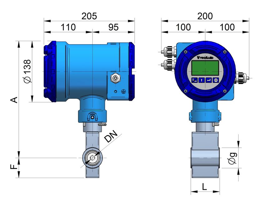
15 DIMENSIONS
(All dimensions in mm)
FLOMID-0FX (EN 1092-1 wafer mounted)
Weight
DN g L F A Ax h
(kg)
3 46 65 45 264 278 176 6.5
6 46 65 45 264 278 176 6.5
10 46 65 45 264 278 176 6.5
15 51 65 48 267 281 179 6.8
20 61 65 54 273 287 185 7.2
25 71 80 36 246 260 158 8.2
32 82 80 41 252 266 164 9.0
40 92 100 46 258 272 170 9.5
50 107 100 54 266 280 178 10.3
65 127 120 64 277 291 189 11.0
80 142 120 71 285 299 197 12.2
100 162 165 81 295 309 207 14.0
125 192 165 96 310 324 222 17.5
150 218 165 109 323 337 235 19.6
FLOMID-0FX (ANSI B16.5 wafer mounted)
Weight
DN g L F A Ax h
(kg)
⅛" 46 65 45 264 278 176 6.5
⅜" 46 65 45 264 278 176 6.5
½" 46 65 45 264 278 176 6.5
¾" 55 65 48 267 281 179 6.8
1" 65 65 54 273 287 185 7.2
1¼" 74 80 37 246 260 158 8.2
1½" 84 80 42 252 266 164 9.0
15
2" 103 100 52 258 272 170 9.5
2½" 122 100 61 266 280 178 10.3
3" 135 120 68 277 291 189 11.0
4" 173 165 87 295 309 207 14.0
5" 192 165 96 310 324 222 17.5
6" 218 165 109 323 337 235 19.6
52DIMENSIONS
15
53You can also read