VEGACAL 62 For connection to a controller - Operating Instructions - For connection to a ...
←
→
Page content transcription
If your browser does not render page correctly, please read the page content below
Operating Instructions
Capacitive rod electrode for continuous
level measurement

VEGACAL 62
For connection to a controller

Document ID: 30317
Contents

Contents
1   About this document................................................................................................................ 4
    1.1 Function............................................................................................................................ 4
    1.2 Target group...................................................................................................................... 4
    1.3 Symbols used................................................................................................................... 4
2   For your safety.......................................................................................................................... 5
    2.1 Authorised personnel........................................................................................................ 5
    2.2 Appropriate use................................................................................................................. 5
    2.3 Warning about incorrect use.............................................................................................. 5
    2.4 General safety instructions................................................................................................ 5
    2.5 EU conformity.................................................................................................................... 5
    2.6 Installation and operation in the USA and Canada............................................................ 6
    2.7 Safety instructions for Ex areas......................................................................................... 6
    2.8 Environmental instructions................................................................................................ 6
3   Product description.................................................................................................................. 7
    3.1 Configuration..................................................................................................................... 7
    3.2 Principle of operation........................................................................................................ 9
    3.3 Adjustment........................................................................................................................ 9
    3.4 Packaging, transport and storage.................................................................................... 10
    3.5 Accessories.................................................................................................................... 10
4   Mounting.................................................................................................................................. 12
    4.1 General instructions........................................................................................................ 12
    4.2 Mounting instructions...................................................................................................... 14
5   Connecting to power supply.................................................................................................. 16
    5.1 Preparing the connection................................................................................................ 16
    5.2 Connection procedure..................................................................................................... 17
    5.3 Wiring plan, single chamber housing.............................................................................. 18
    5.4 Wiring plan - version IP66/IP68, 1 bar............................................................................. 19
6   Setup with a controller........................................................................................................... 20
    6.1 General information......................................................................................................... 20
    6.2 Adjustment system.......................................................................................................... 20
    6.3 Continuous level measurement....................................................................................... 21
7   Maintenance and fault rectification....................................................................................... 23
    7.1 Maintenance................................................................................................................... 23
    7.2 Rectify faults.................................................................................................................... 23
    7.3 Exchanging the electronics module................................................................................. 24
    7.4 Shortening the electrode................................................................................................. 25
    7.5 How to proceed if a repair is necessary........................................................................... 25
8   Dismount................................................................................................................................. 26
    8.1 Dismounting steps.......................................................................................................... 26
    8.2 Disposal.......................................................................................................................... 26
                                                                                                                                                    30317-EN-200929

9   Supplement............................................................................................................................. 27
    9.1 Technical data................................................................................................................. 27
    9.2 Dimensions..................................................................................................................... 31
    9.3 Industrial property rights.................................................................................................. 35
    9.4 Trademark....................................................................................................................... 35

2                                                                                     VEGACAL 62 • For connection to a controller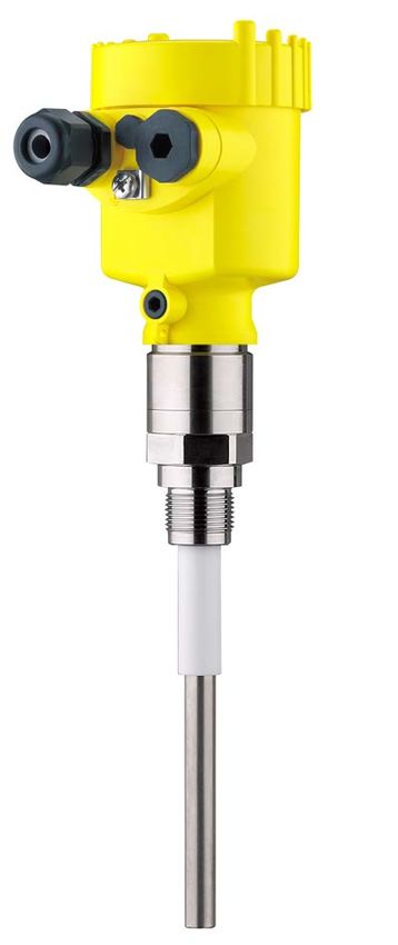
Contents
30317-EN-200929

                                                  Editing status: 2020-09-24

                  VEGACAL 62 • For connection to a controller                         3
1 About this document
1 About this document
1.1 Function
This instruction provides all the information you need for mounting,
connection and setup as well as important instructions for mainte-
nance, fault rectification, the exchange of parts and the safety of the
user. Please read this information before putting the instrument into
operation and keep this manual accessible in the immediate vicinity
of the device.
1.2 Target group
This operating instructions manual is directed to trained personnel.
The contents of this manual must be made available to the qualified
personnel and implemented.
1.3 Symbols used
Document ID
This symbol on the front page of this instruction refers to the Docu-
ment ID. By entering the Document ID on www.vega.com you will
reach the document download.
Information, note, tip: This symbol indicates helpful additional infor-
mation and tips for successful work.
Note: This symbol indicates notes to prevent failures, malfunctions,
damage to devices or plants.
Caution: Non-observance of the information marked with this symbol
may result in personal injury.
Warning: Non-observance of the information marked with this symbol
may result in serious or fatal personal injury.
Danger: Non-observance of the information marked with this symbol
results in serious or fatal personal injury.
Ex applications
This symbol indicates special instructions for Ex applications.
• List
The dot set in front indicates a list with no implied sequence.
1 Sequence of actions
Numbers set in front indicate successive steps in a procedure.
Battery disposal
This symbol indicates special information about the disposal of bat-
teries and accumulators.
30317-EN-200929
4 VEGACAL 62 • For connection to a controller2 For your safety
2 For your safety
2.1 Authorised personnel
All operations described in this documentation must be carried out
only by trained, qualified personnel authorised by the plant operator.
During work on and with the device, the required personal protective
equipment must always be worn.
2.2 Appropriate use
VEGACAL 62 is a sensor for continuous level measurement.
You can find detailed information about the area of application in
chapter " Product description".
Operational reliability is ensured only if the instrument is properly
used according to the specifications in the operating instructions
manual as well as possible supplementary instructions.
2.3 Warning about incorrect use
Inappropriate or incorrect use of this product can give rise to applica-
tion-specific hazards, e.g. vessel overfill through incorrect mounting
or adjustment. Damage to property and persons or environmental
contamination can result. Also, the protective characteristics of the
instrument can be impaired.
2.4 General safety instructions
This is a state-of-the-art instrument complying with all prevailing
regulations and directives. The instrument must only be operated in a
technically flawless and reliable condition. The operator is responsi-
ble for the trouble-free operation of the instrument. When measuring
aggressive or corrosive media that can cause a dangerous situation
if the instrument malfunctions, the operator has to implement suitable
measures to make sure the instrument is functioning properly.
The safety instructions in this operating instructions manual, the na-
tional installation standards as well as the valid safety regulations and
accident prevention rules must be observed by the user.
For safety and warranty reasons, any invasive work on the device
beyond that described in the operating instructions manual may be
carried out only by personnel authorised by the manufacturer. Arbi-
trary conversions or modifications are explicitly forbidden. For safety
reasons, only the accessory specified by the manufacturer must be
used.
To avoid any danger, the safety approval markings and safety tips on
the device must also be observed.
30317-EN-200929
2.5 EU conformity
The device fulfils the legal requirements of the applicable EU direc-
tives. By affixing the CE marking, we confirm the conformity of the
instrument with these directives.
The EU conformity declaration can be found on our homepage.
VEGACAL 62 • For connection to a controller 52 For your safety
2.6 Installation and operation in the USA and
Canada
This information is only valid for USA and Canada. Hence the follow-
ing text is only available in the English language.
Installations in the US shall comply with the relevant requirements of
the National Electrical Code (ANSI/NFPA 70).
Installations in Canada shall comply with the relevant requirements of
the Canadian Electrical Code.
2.7 Safety instructions for Ex areas
For Ex applications, only devices with corresponding Ex approval may
be used. Observe the Ex-specific safety instructions. These are an
integral part of the operating instructions and are enclosed with every
device with Ex approval.
2.8 Environmental instructions
Protection of the environment is one of our most important duties.
That is why we have introduced an environment management system
with the goal of continuously improving company environmental pro-
tection. The environment management system is certified according
to DIN EN ISO 14001.
Please help us fulfil this obligation by observing the environmental
instructions in this manual:
• Chapter " Packaging, transport and storage"
• Chapter " Disposal"
30317-EN-200929
6 VEGACAL 62 • For connection to a controller3 Product description
3 Product description
3.1 Configuration
Scope of delivery The scope of delivery encompasses:
• Level sensor VEGACAL 62
The further scope of delivery encompasses:
• Documentation
–– Operating instructions VEGACAL 62
–– Instructions for optional instrument features
–– Ex-specific " Safety instructions" (with Ex versions)
–– If necessary, further certificates
Information:
Optional instrument features are also described in this operating
instructions manual. The respective scope of delivery results from the
order specification.
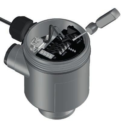
Constituent parts The VEGACAL 62 consists of the components:
• Process fitting with probe
• Housing with electronics
• Housing lid
1
2
3
Fig. 1: VEGACAL 62, rod version with plastic housing
1 Housing lid
2 Housing with electronics
3 Process fitting
Scope of this operating This operating instructions manual applies to the following instrument
30317-EN-200929
instructions versions:
• Hardware from 1.0.0
• Software from 1.3.0
• Only for instrument versions without SIL qualification
VEGACAL 62 • For connection to a controller 73 Product description
Type label The type label contains the most important data for identification and
use of the instrument:
1 15
2 14
3 13
4 12
5 11
6 10
7 9
8
Fig. 2: Layout of the type label (example)
1 Instrument type
2 Product code
3 Approvals
4 Process and ambient temperature, process pressure
5 Power supply and signal output, electronics
6 Protection rating
7 Probe length
8 Order number
9 Serial number of the instrument
10 Material wetted parts
11 Symbol of the device protection class
12 Reminder to observe the instrument documentation
13 ID numbers, instrument documentation
14 Notified authority for CE marking
15 Approval directives
With the serial number, you can access the delivery data of the instru-
ment via " www.vega.com", " Search". You can find the serial number
on the inside of the instrument as well as on the type label on the
outside.
Serial number - Instru- The type label contains the serial number of the instrument. With it
ment search you can find the following instrument data on our homepage:
• Product code (HTML)
• Delivery date (HTML)
• Order-specific instrument features (HTML)
• Operating instructions and quick setup guide at the time of ship-
ment (PDF)
• Order-specific sensor data for an electronics exchange (XML)
• Test certificate (PDF) - optional
Move to " www.vega.com" and enter in the search field the serial
number of your instrument.
30317-EN-200929
Alternatively, you can access the data via your smartphone:
• Download the VEGA Tools app from the " Apple App Store" or the
" Google Play Store"
• Scan the DataMatrix code on the type label of the instrument or
• Enter the serial number manually in the app
8 VEGACAL 62 • For connection to a controller3 Product description
3.2 Principle of operation
Application area VEGACAL 62 is a level sensor for continuous level measurement in all
areas of industry.
The partly insulated probe is designed for measurement of bulk solids
and can be also used in non-conductive liquids such as for example
oil.
The proven mechanical construction offers high functional safety.
Functional principle Probe, measured product and vessel wall form an electrical capacitor.
The capacitance is influenced by three main factors.
1
2
3
Fig. 3: Functional principle - Plate capacitor
1 Distance between the electrode surfaces
2 Size of the electrode surfaces
3 Type of dielectric between the electrodes
The probe and the vessel wall are the capacitor plates. The measured
product is the dielectric. Due to the higher dielectric constant of the
product compared to air, the capacitance increases as the probe is
gradually covered.
The capacitance as well as the resistance change are converted by
the electronics module into a level-proportional signal.
Voltage supply 4 … 20 mA two-wire electronics for voltage supply and measured
value transmission on the same cable.
The supply voltage range can differ depending on the instrument
version.
The data for power supply are specified in chapter "Technical data".
3.3 Adjustment
VEGACAL 62 measurement signals can be evaluated with the follow-
ing:
• With a VEGAMET controller
30317-EN-200929
The measuring range must be selected on the electronics module of
the probe.
The full and empty adjustment can be carried out on a VEGAMET
controller or the analogue input card of a PLC.
VEGACAL 62 • For connection to a controller 93 Product description
3.4 Packaging, transport and storage
Packaging Your instrument was protected by packaging during transport. Its
capacity to handle normal loads during transport is assured by a test
based on ISO 4180.
The packaging of standard instruments consists of environment-
friendly, recyclable cardboard. For special versions, PE foam or PE
foil is also used. Dispose of the packaging material via specialised
recycling companies.
Transport Transport must be carried out in due consideration of the notes on the
transport packaging. Nonobservance of these instructions can cause
damage to the device.
Transport inspection The delivery must be checked for completeness and possible transit
damage immediately at receipt. Ascertained transit damage or con-
cealed defects must be appropriately dealt with.
Storage Up to the time of installation, the packages must be left closed and
stored according to the orientation and storage markings on the
outside.
Unless otherwise indicated, the packages must be stored only under
the following conditions:
• Not in the open
• Dry and dust free
• Not exposed to corrosive media
• Protected against solar radiation
• Avoiding mechanical shock and vibration
Storage and transport • Storage and transport temperature see chapter " Supplement -
temperature Technical data - Ambient conditions"
• Relative humidity 20 … 85 %
Lifting and carrying With instrument weights of more than 18 kg (39.68 lbs) suitable and
approved equipment must be used for lifting and carrying.
3.5 Accessories
The instructions for the listed accessories can be found in the down-
load area on our homepage.
VEGACONNECT The interface adapter VEGACONNECT enables the connection of
communication-capable instruments to the USB interface of a PC.
VEGADIS 81 The VEGADIS 81 is an external display and adjustment unit for VEGA
plics® sensors.
VEGADIS 82 VEGADIS 82 is suitable for measured value indication and adjustment
30317-EN-200929
of sensors with HART protocol. It is looped into the 4 … 20 mA/HART
signal cable.
10 VEGACAL 62 • For connection to a controller3 Product description
PLICSMOBILE T81 The PLICSMOBILE T81 is an external GSM/GPRS/UMTS radio unit
for transmission of measured values and for remote parameter adjust-
ment of HART sensors.
External housing If the standard sensor housing is too big or in case of strong vibra-
tions, an external housing can be used.
Then the sensor housing is made of stainless steel. The electronics is
located in the external housing which can be mounted in a distance of
up to 10 m (32.8 ft) to the sensor by using a connection cable.
Three different external sensor housings are available.
1
2
3
A
Fig. 4: External housing
A Instrument housing
1 Sensor housing, stainless steel (316L), IP68 (10 bar)
2 Sensor housing, stainless steel (316L), IP67
3 Sensor housing, stainless steel (316L), BNC plug IP54
Protective cover The protective cover protects the sensor housing against soiling and
intense heat from solar radiation.
Flanges Screwed flanges are available in different versions according to the
following standards: DIN 2501, EN 1092-1, BS 10, ASME B 16.5,
JIS B 2210-1984, GOST 12821-80.
30317-EN-200929
VEGACAL 62 • For connection to a controller 114 Mounting
4 Mounting
4.1 General instructions
Process conditions Note:
For safety reasons, the instrument must only be operated within the
permissible process conditions. You can find detailed information on
the process conditions in chapter " Technical data" of the operating
instructions or on the type label.
Hence make sure before mounting that all parts of the instrument ex-
posed to the process are suitable for the existing process conditions.
These are mainly:
• Active measuring component
• Process fitting
• Process seal
Process conditions in particular are:
• Process pressure
• Process temperature
• Chemical properties of the medium
• Abrasion and mechanical influences
Installation position Select such a mounting location that the instrument is within easy
reach for mounting and connecting. For this purpose the housing can
be rotated by 330° without any tools being required.
Screwing in Devices with threaded fitting are screwed into the process fitting with
a suitable wrench via the hexagon.
See chapter " Dimensions" for wrench size.
Warning:
The housing or the electrical connection may not be used for screw-
ing in! Depending on the device version, tightening can cause dam-
age, e. g. to the rotation mechanism of the housing.
Welding work Before beginning the welding work, remove the electronics module
from the sensor. By doing this, you avoid damage to the electronics
through inductive coupling.
Ground the probe before welding directly on the rod or cable.
Handling With threaded versions, the housing must not be used to screw in the
instrument! Applying tightening forces on the housing can damage its
internal parts.
Use the hexagon for screwing in.
30317-EN-200929
Protection against mois- Use the recommended cables (see chapter " Connecting to power
ture supply") and tighten the cable gland.
You can give your instrument additional protection against moisture
penetration by leading the connection cable downward in front of the
cable gland. Rain and condensation water can thus drain off. This
12 VEGACAL 62 • For connection to a controller4 Mounting
applies mainly to outdoor mounting as well as installation in areas
where high humidity is expected (e.g. through cleaning processes) or
on cooled or heated vessels.
To maintain the housing protection, make sure that the housing lid is
closed during operation and locked, if necessary.
Fig. 5: Measures against moisture ingress
Pressure/Vacuum The process fitting must be sealed if there is gauge or low pressure
in the vessel. Before use, check if the sealing material is resistant
against the measured product and the process temperature.
The max. permissible pressure is specified in chapter " Technical
data" or on the type label of the sensor.
Insulating measures, such as e.g. covering the thread with teflon tape,
can interrupt the necessary electrical connection with metal vessels.
For this reason, ground the probe on the vessel or use a conductive
seal material.
Vessel material Metal vessel
Make sure that the mechanical connection of the probe to the vessel
is electrically conductive to ensure sufficient grounding.
Use conductive seals, such as those made of copper or lead, etc.
Insulating measures, such as covering the thread with Teflon tape,
can interrupt the necessary electrical connection with metal vessels.
For this reason, ground the probe on the vessel or use a conductive
seal material.
Non-conductive vessels
In non-conductive vessels, e.g. plastic tanks, the second pole of the
capacitor must be provided separately, e.g. in the form of a concentric
tube.
Vessel shapes If possible, the capacitive probe should be mounted vertically or par-
allel to the counter electrode. This applies particularly to applications
in non-conductive products.
In cylindrical tanks, spherical tanks or other asymmetrical tank forms,
30317-EN-200929
nonlinear level values are generated due to the varying distance to
the vessel wall.
Use a concentric tube in non-conductive products or linearize the
meas. signal.
VEGACAL 62 • For connection to a controller 134 Mounting
Condensation If condensate forms on the vessel top, the run-off liquid can cause
bridging and hence measurement errors.
For this reason, use a screening tube or a longer insulation. The
length depends on the amount of condensate and the drain-off be-
haviour of the product.
Cable entries - NPT Metric threads
thread In the case of instrument housings with metric thread, the cable
Cable glands glands are screwed in at the factory. They are sealed with plastic
plugs as transport protection.
You have to remove these plugs before electrical connection.
NPT thread
In the case of instrument housings with self-sealing NPT threads, it is
not possible to have the cable entries screwed in at the factory. The
free openings for the cable glands are therefore covered with red dust
protection caps as transport protection.
Prior to setup you have to replace these protective caps with ap-
proved cable glands or close the openings with suitable blind plugs.
4.2 Mounting instructions
Installation position During operation, the probe must not touch any installations or the
vessel wall. The measured value can also change if the distance to
the vessel wall changes considerably. If necessary, secure the end of
the probe (insulated).
1 1
2 2
Fig. 6: Fasten the probe
1 Measuring probe
2 Plastic socket
In vessels with conical bottom it can be advantageous to mount the
sensor in the centre of the vessel, as measurement is then possible
down to the bottom.
Inflowing medium If the instrument is mounted in the filling stream, unwanted false
measurement signals can be generated. For this reason, mount the
instrument at a position in the vessel where no disturbances, e.g. from
filling openings, agitators, etc., can occur.
30317-EN-200929
This applies particularly to instrument versions with a longer probe.
14 VEGACAL 62 • For connection to a controller4 Mounting
Fig. 7: Inflowing medium
30317-EN-200929
VEGACAL 62 • For connection to a controller 155 Connecting to power supply
5 Connecting to power supply
5.1 Preparing the connection
Safety instructions Always keep in mind the following safety instructions:
• Carry out electrical connection by trained, qualified personnel
authorised by the plant operator
• If overvoltage surges are expected, overvoltage arresters should
be installed
Warning:
Only connect or disconnect in de-energized state.
Voltage supply Power supply and current signal are carried on the same two-wire
cable. The operating voltage can differ depending on the instrument
version.
The data for power supply are specified in chapter "Technical data".
Provide a reliable separation between the supply circuit and the
mains circuits according to DIN EN 61140 VDE 0140-1.
Power the instrument via an energy-limited circuit acc. to IEC 61010-
1, e.g. via Class 2 power supply unit.
Keep in mind the following additional factors that influence the operat-
ing voltage:
• Lower output voltage of the power supply unit under nominal load
(e.g. with a sensor current of 20.5 mA or 22 mA in case of fault)
• Influence of additional instruments in the circuit (see load values in
chapter "Technical data")
Connection cable The instrument is connected with standard two-wire cable without
shielding. If electromagnetic interference is expected which is above
the test values of EN 61326-1 for industrial areas, shielded cable
should be used.
Use cable with round cross section for instruments with housing and
cable gland. Use a cable gland suitable for the cable diameter to
ensure the seal effect of the cable gland (IP protection rating).
We generally recommend the use of shielded cable for HART
multidrop mode.
Cable glands Metric threads
In the case of instrument housings with metric thread, the cable
glands are screwed in at the factory. They are sealed with plastic
plugs as transport protection.
Note:
You have to remove these plugs before electrical connection.
30317-EN-200929
NPT thread
In the case of instrument housings with self-sealing NPT threads, it is
not possible to have the cable entries screwed in at the factory. The
free openings for the cable glands are therefore covered with red dust
protection caps as transport protection.
16 VEGACAL 62 • For connection to a controller5 Connecting to power supply
Note:
Prior to setup you have to replace these protective caps with ap-
proved cable glands or close the openings with suitable blind plugs.
On plastic housings, the NPT cable gland or the Conduit steel tube
must be screwed into the threaded insert without grease.
Max. torque for all housings, see chapter " Technical data".
Cable screening and If shielded cable is required, we recommend connecting the cable
grounding screening on both ends to ground potential. In the sensor, the cable
screening must be connected directly to the internal ground terminal.
The ground terminal on the outside of the housing must be connected
to the ground potential (low impedance).
In Ex systems, the grounding is carried out according to the installa-
tion regulations.
In electroplating plants as well as plants for cathodic corrosion protec-
tion it must be taken into account that significant potential differences
exist. This can lead to unacceptably high currents in the cable screen
if it is grounded at both ends.
Note:
The metallic parts of the instrument (process fitting, sensor, concen-
tric tube, etc.) are connected with the internal and external ground
terminal on the housing. This connection exists either directly via
the conductive metallic parts or, in case of instruments with external
electronics, via the screen of the special connection cable.
You can find specifications on the potential connections inside the
instrument in chapter "Technical data".
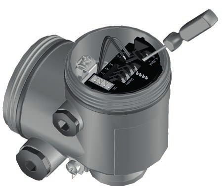
5.2 Connection procedure
Proceed as follows:
1. Unscrew the housing lid
2. Loosen compression nut of the cable gland and remove blind
plug
3. Remove approx. 10 cm (4 in) of the cable mantle, strip approx.
1 cm (0.4 in) of insulation from the ends of the individual wires
4. Insert the cable into the sensor through the cable entry
5. Lift the opening levers of the terminals with a screwdriver (see
following illustration)
6. Insert the wire ends into the open terminals according to the wir-
ing plan
7. Press down the opening levers of the terminals, you will hear the
terminal spring closing
8. Check the hold of the wires in the terminals by lightly pulling on
30317-EN-200929
them
9. Connect the shielding to the internal ground terminal, connect the
external ground terminal to potential equalisation
VEGACAL 62 • For connection to a controller 175 Connecting to power supply
10. Tighten the compression nut of the cable entry gland. The seal
ring must completely encircle the cable
11. Screw the housing lid back on
The electrical connection is finished.
Fig. 8: Connection steps 6 and 7
5.3 Wiring plan, single chamber housing
The following illustrations apply to the non-Ex as well as to the Ex-ia
version.
Housing overview
5 5 5
1 2 3
5
4
Fig. 9: Material versions, single chamber housing
1 Plastic
2 Aluminium
3 Stainless steel (precision casting)
4 Stainless steel (electro-polished)
5 Filter element for air pressure compensation of all material versions. Blind
plug with version IP66/IP68, 1 bar for Aluminium and stainless steel
30317-EN-200929
18 VEGACAL 62 • For connection to a controller5 Connecting to power supply
Electronics and connec-
tion compartment
1 2
2
1
Fig. 10: Electronics and connection compartment - single chamber housing
1 Ground terminal for connection of the cable screening
2 Spring-loaded terminals for voltage supply
Wiring plan
1 2
1
Fig. 11: Wiring plan - single chamber housing
1 Voltage supply/Signal output
5.4 Wiring plan - version IP66/IP68, 1 bar
Wire assignment, con-
nection cable
1
2
Fig. 12: Wire assignment, connection cable
30317-EN-200929
1 Brown (+) and blue (-) to power supply or to the processing system
2 Shielding
VEGACAL 62 • For connection to a controller 196 Setup with a controller
6 Setup with a controller
6.1 General information
Function/Configuration During setup, the probe must be calibrated with the medium that will
later be measured. To adjust the probe, open the housing cover. You
can select the sensitivity range on the electronics module by means
of the measuring range selection switch.
• range 1: 0 … 120 pF
• Range 2: 0 … 600 pF
• Range 3: 0 … 3000 pF
The adjustment is described in the operating instructions manual of
the respective controller.
6.2 Adjustment system
1
3
2
Fig. 13: Display and adjustment elements - Oscillator
1 DIL switch for measuring range selection
2 Ground terminal
3 Connection terminals
Measuring range selec- With the measuring range selection switch (1) you can adapt the
tion switch (1) sensitivity of the probe to the electrical properties of the measured
medium and the conditions in the vessel. This is necessary to ensure
that the output current range is a big as possible. The resolution of the
probe is thus also correspondingly increased.
Due to this, the probe can for example also detect products with very
low or very high dielectric constant reliably.
•
30317-EN-200929
range 1 (sensitive): 0 … 120 pF
• range 2 (standard): 0 … 600 pF
• range 3 (less sensitive): 0 … 3000 pF
20 VEGACAL 62 • For connection to a controller6 Setup with a controller
6.3 Continuous level measurement
General information Continuous measurement requires a constant dielectric value, i.e. the
measured product should have constant properties.
Select the stage with the measuring range selection switch on the
electronics module of the probe according to the following table.
Look in the row that corresponds to your product and select an ap-
propriate range according to the length of your probe.
The listed lengths do not completely correspond to those of the
actually available measuring probes. If the product has a dielectric
constant that lies between the values stated in the table, the max. per-
missible probe length for each range must be calculated accordingly.
For longer lengths or if there is no information available in the chart,
select range 3. If you are not sure, always set the measuring range
selection switch to the next higher stage.
VEGACAL 62 VEGACAL 62 with concentric tube
non-conductive and dielectric con- 0 - 5.5 m = range 1 0 - 1.5 m = range 1
stant = 2
non-conductive and dielectric con- 0 - 0.8 m = range 1 0 - 0.15 m = range 1
stant = 10 0.8 - 4.5 m = range 2 0.15 - 0.9 m = range 2
conductive or dielectric con- - -
stant > 50
Tab. 1: Range setting
Tip:
For min. adjustment the vessel should be as empty as possible, and
for max. adjustment, as full as possible. If the vessel is already full,
start with max. adjustment.
Analogue input card of 1. Set range changeover switch on the capacitive probe according
a PLC to the above table
2. When connecting to an analogue input card of a PLC, take note
of the operating instructions manual of the input card. The vessel
must be as empty as possible for empty adjustment and as full as
possible for full adjustment.
If the indication cannot be set to 100 %, proceed as follows:
• If the indication does not reach 100 %, you have to set the range
selection switch on the probe one stage lower.
• If the indication exceeds 100 % and cannot be reset, you have
to set the range selection switch of the probe to the next higher
stage. In both cases you have to repeat the adjustment.
VEGAMET series 300, 600 1. Set range changeover switch on the capacitive probe according
controller to the above table
2. Carry out the adjustment on the controller (see operating
30317-EN-200929
instructions manual of the controller: "Adjustment with medium")
When connecting to an analogue input card of a PLC, take note of the
operating instructions manual of the input card. The vessel must be as
empty as possible for empty adjustment and as full as possible for full
adjustment.
VEGACAL 62 • For connection to a controller 216 Setup with a controller
If the indication cannot be set to 100 %, proceed as follows:
• If the indication does not reach 100 %, you have to set the range
selection switch on the probe one stage lower.
• If the indication exceeds 100 % and cannot be reset, you have
to set the range selection switch of the probe to the next higher
stage. In both cases you have to repeat the adjustment.
30317-EN-200929
22 VEGACAL 62 • For connection to a controller7 Maintenance and fault rectification
7 Maintenance and fault rectification
7.1 Maintenance
Maintenance If the device is used properly, no special maintenance is required in
normal operation.
Cleaning The cleaning helps that the type label and markings on the instrument
are visible.
Take note of the following:
• Use only cleaning agents which do not corrode the housings, type
label and seals
• Use only cleaning methods corresponding to the housing protec-
tion rating
7.2 Rectify faults
Reaction when malfunc- The operator of the system is responsible for taking suitable meas-
tion occurs ures to rectify faults.
Causes of malfunction The device offers maximum reliability. Nevertheless, faults can occur
during operation. These may be caused by the following, e.g.:
• Sensor
• Process
• Voltage supply
• Signal processing
Fault rectification The first measure to take is to check the output signal. In many cases,
the causes can be determined this way and the faults quickly rectified.
Reaction after fault recti- Depending on the reason for the fault and the measures taken, the
fication steps described in chapter " Setup" must be carried out again or must
be checked for plausibility and completeness.
24 hour service hotline Should these measures not be successful, please call in urgent cases
the VEGA service hotline under the phone no. +49 1805 858550.
The hotline is also available outside normal working hours, seven
days a week around the clock.
Since we offer this service worldwide, the support is provided in
English. The service itself is free of charge, the only costs involved are
the normal call charges.
Checking the current Connect a multimeter in the suitable measuring range according to
signal the wiring plan.
Error Cause Rectification
30317-EN-200929
Current signal not stable Level fluctuations Adjust damping in the controller or process control sys-
tem
VEGACAL 62 • For connection to a controller 237 Maintenance and fault rectification
Error Cause Rectification
Current signal missing Wrong connection to volt- Check connection according to chapter "Connection
age supply steps" and if necessary, correct according to chapter
"Wiring plan"
No power supply Check cables for breaks; repair if necessary
Operating voltage too low Check, adapt if necessary
or load resistance too high
Current signal >22 mA Short-circuit due to bridg- Remove buildup - if necessary, mount a protective tube
ing by conductive buildup
between process fitting
and electrode
Shortcircuit in the probe, Remove the electronics module. Check the resistance
e.g. because of moisture in between the marked plug connections. See the follow-
the housing ing instructions.
Electronics module de- Exchange the instrument or send it in for repair
fective
Check the resistance in Remove the electronics module. Check the resistance between the
the probe two plug connections.
There must no longer be a connection (high impedance). If there is
still a connection, exchange the instrument or return it for repair
2 1 3
Fig. 14: Check the resistance in the probe
1 Shielding
2 Measuring probe
3 Ground potential
In Ex applications, the regulations for the wiring of intrinsically safe
circuits must be observed.
7.3 Exchanging the electronics module
30317-EN-200929
If the electronics module is defective, it can be replaced by the user.
In Ex applications, only instruments and electronics modules with ap-
propriate Ex approval may be used.
24 VEGACAL 62 • For connection to a controller7 Maintenance and fault rectification
If there is no electronics module available on site, one can be ordered
from the VEGA agency serving you.
Assignment The electronics modules are adapted to the respective sensor. You
can find a suitable electronics module in the following overview.
• CL-E60ZX (without approvals)
7.4 Shortening the electrode
The probe (rod) can be shortened by any length.
1. Shorten the rod with a cut-off wheel or metal saw at the lower
end. Make sure the length is correct before shortening.
2. Carry out a fresh adjustment
7.5 How to proceed if a repair is necessary
You can find an instrument return form as well as detailed informa-
tion about the procedure in the download area of our homepage:
www.vega.com.
By doing this you help us carry out the repair quickly and without hav-
ing to call back for needed information.
If a repair is necessary, please proceed as follows:
• Print and fill out one form per instrument
• Clean the instrument and pack it damage-proof
• Attach the completed form and, if need be, also a safety data
sheet outside on the packaging
• Please contact the agency serving you to get the address for
the return shipment. You can find the agency on our home page
www.vega.com.
30317-EN-200929
VEGACAL 62 • For connection to a controller 258 Dismount
8 Dismount
8.1 Dismounting steps
Warning:
Before dismounting, be aware of dangerous process conditions such
as e.g. pressure in the vessel or pipeline, high temperatures, cor-
rosive or toxic media etc.
Take note of chapters " Mounting" and " Connecting to voltage sup-
ply" and carry out the listed steps in reverse order.
8.2 Disposal
The instrument consists of materials which can be recycled by spe-
cialised recycling companies. We use recyclable materials and have
designed the electronics to be easily separable.
WEEE directive
The instrument does not fall in the scope of the EU WEEE directive.
Article 2 of this Directive exempts electrical and electronic equipment
from this requirement if it is part of another instrument that does not
fall in the scope of the Directive. These include stationary industrial
plants.
Pass the instrument directly on to a specialised recycling company
and do not use the municipal collecting points.
If you have no way to dispose of the old instrument properly, please
contact us concerning return and disposal.
30317-EN-200929
26 VEGACAL 62 • For connection to a controller9 Supplement
9 Supplement
9.1 Technical data
Note for approved instruments
The technical data in the respective safety instructions which are included in delivery are valid for
approved instruments (e.g. with Ex approval). These data can differ from the data listed herein, for
example regarding the process conditions or the voltage supply.
All approval documents can be downloaded from our homepage.
General data
Material 316L corresponds to 1.4404 or 1.4435
Materials, wetted parts
ƲƲ Process fitting - thread 316L, St C22.8 (1.0460)
ƲƲ Process fitting - flange 316L
ƲƲ Process seal Klingersil C-4400 (Geräte mit Einschraubgewinde)
ƲƲ Insulation (partly insulated) PTFE, PEEK
ƲƲ Electrode (rod partly PTFE insulated: 316L
ø 12 mm/0.472 in)
ƲƲ Electrode (rod partly PEEK insulated: 316L
ø 12 mm/0.472 in)
Materials, non-wetted parts
ƲƲ Plastic housing Plastic PBT (Polyester)
ƲƲ Aluminium die-cast housing Aluminium die-casting AlSi10Mg, powder-coated (Basis:
Polyester)
ƲƲ Stainless steel housing (precision 316L
casting)
ƲƲ Stainless steel housing (electropol- 316L
ished)
ƲƲ Seal between housing and housing lid Silicone
ƲƲ Inspection window in housing cover Plastic housing: Polycarbonate (UL746-C listed)
(optional) Metal housing: Glass 1)
ƲƲ Ground terminal 316L
ƲƲ Cable gland PA, stainless steel, brass
ƲƲ Sealing (cable gland) NBR
ƲƲ Blind plug (cable gland) PA
Process fittings
ƲƲ Pipe thread, cylindrical (DIN 3852-A) G½, G¾, G1, G1½
ƲƲ Pipe thread, conical (ASME B1.20.1) ½ NPT, ¾ NPT, 1 NPT, 1½ NPT
ƲƲ Flanges DIN from DN 20, ASME from 1"
30317-EN-200929
Weight
ƲƲ Instrument weight (depending on 0.8 … 4 kg (0.18 … 8.82 lbs)
process fitting)
1)
Aluminium, stainless steel precision casting and Ex d housing
VEGACAL 62 • For connection to a controller 279 Supplement
ƲƲ Rod weight: ø 12 mm (0.472 in) 900 g/m (9.9 oz/ft)
Sensor length (L) 0.1 … 6 m (0.328 … 19.69 ft)
Max. lateral load 10 Nm (7.4 lbf ft)
Max. torque (process fitting - thread) 100 Nm (73 lbf ft)
Torque for NPT cable glands and Conduit tubes
ƲƲ Plastic housing max. 10 Nm (7.376 lbf ft)
ƲƲ Aluminium/Stainless steel housing max. 50 Nm (36.88 lbf ft)
Output variable
Output signal in the range of 4 … 20 mA
Suitable controllers e.g. VEGAMET 141, 381, 391, 624, 841, 842, 861, 862
Fault message > 22 mA
Current limitation 28 mA
Load see load diagram under Power supply
Damping (63 % of the input variable) 0.1 s
Met NAMUR recommendation NE 43
Input variable
Measured variable level of non-conductive liquids and solids
Measuring principle phase-selective admittance processing (PSA)
Measuring range
ƲƲ range 1 0 … 120 pF
ƲƲ range 2 0 … 600 pF
ƲƲ range 3 0 … 3000 pF
Measuring frequency 430 kHz
Measurement accuracy (according to DIN EN 60770-1)
Reference conditions according to DIN EN 61298-1
ƲƲ Temperature +18 … +30 °C (+64 … +86 °F)
ƲƲ Relative humidity 45 … 75 %
ƲƲ Air pressure +860 … +1060 mbar/+86 … +106 kPa
(+12.5 … +15.4 psig)
Temperature error
ƲƲ < 120 pF < 1 pF
ƲƲ > 120 pF 1 % of the current measured value
Linearity error < 0.25 % of the complete measuring range
Ambient conditions
Ambient, storage and transport tempera- -40 … +80 °C (-40 … +176 °F)
30317-EN-200929
ture
28 VEGACAL 62 • For connection to a controller9 Supplement
Process conditions
For the process conditions, please also note the specifications on the type label. The lowest value
always applies.
Process pressure
ƲƲ Standard -1 … +64 bar/-100 … +6400 kPa (-14.5 … +928 psig)
ƲƲ with screening tube adapter (PN1) 0 … +1 bar/0 … 100 kPa (0 … 14.5 psig)
Process temperature VEGACAL 62 of -50 … +150 °C (-58 … +302 °F)
316L
Process temperature (thread or flange -50 … +200 °C (-58 … +392 °F)
temperature) with temperature adapter
(option) 2)
Process temperature VEGACAL 62 of St -20 … +150 °C (-4 … +302 °F)
C22.8
2
3
80°C
(176°F)
40°C
(104°F)
0°C
1
(32°F)
-50°C 50°C 100°C 150°C 200°C
(-58°F) (122°F) (212°F) (302°F) (392°F)
-40°C
(-40°F)
Fig. 15: Ambient temperature - Process temperature
1 Process temperature
2 Ambient temperature
3 Temperature range with temperature adapter
Dielectric constant ≥ 1.5
Electromechanical data - version IP66/IP67 and IP66/IP68; (0.2 bar)
Options of the cable entry
ƲƲ Cable entry M20 x 1.5; ½ NPT3)
ƲƲ Cable gland M20 x 1.5; ½ NPT
ƲƲ Blind plug M20 x 1.5; ½ NPT
ƲƲ Closing cap ½ NPT
Wire cross-section (spring-loaded terminals)
ƲƲ Massive wire, stranded wire 0.2 … 2.5 mm² (AWG 24 … 14)
ƲƲ Stranded wire with end sleeve 0.2 … 1.5 mm² (AWG 24 … 16)
30317-EN-200929
2)
Only in conjunction with PTFE insulation.
3)
Depending on the version M12 x 1, according to ISO 4400, Harting, 7/8" FF.
VEGACAL 62 • For connection to a controller 299 Supplement
Electromechanical data - version IP66/IP68 (1 bar)
Cable entry
ƲƲ Single chamber housing –– 1 x IP68 cable gland M20 x 1.5; 1 x blind plug
M20 x 1.5
or:
–– 1 x closing cap ½ NPT, 1 x blind plug ½ NPT
Voltage supply
Operating voltage 12 … 36 V DC
Ω
1000
750
2
500
1
250
3
12 14 16 18 20 22 24 26 28 30 32 34 36 V
Fig. 16: Voltage diagram
1 Voltage limit Ex-ia instrument
2 Voltage limit non-Ex
3 Operating voltage
Permissible residual ripple
ƲƲ < 100 Hz Uss < 1 V
ƲƲ 100 Hz … 10 kHz Uss < 10 mV
Load see diagram
Potential connections and electrical separating measures in the instrument
Electronics Not non-floating
Reference voltage 4) 500 V AC
Conductive connection Between ground terminal and metallic process fitting
Electrical protective measures
Protection rating
Housing material Version IP-protection class NEMA protection
Plastic Single chamber IP66/IP67 Type 4X
Double chamber IP66/IP67 Type 4X
30317-EN-200929
4)
Galvanic separation between electronics and metal housing parts
30 VEGACAL 62 • For connection to a controller9 Supplement
Housing material Version IP-protection class NEMA protection
Aluminium Single chamber IP66/IP68 (0.2 bar) Type 6P
IP68 (1 bar) Type 6P
Double chamber IP66/IP67 Type 4X
IP66/IP68 (0.2 bar) Type 6P
IP68 (1 bar) Type 6P
Stainless steel (electro- Single chamber IP66/IP68 (0.2 bar) Type 6P
polished)
Stainless steel (precision Single chamber IP66/IP68 (0.2 bar) Type 6P
casting) IP68 (1 bar) Type 6P
Double chamber IP66/IP67 Type 4X
IP66/IP68 (0.2 bar) Type 6P
IP68 (1 bar) Type 6P
Connection of the feeding power supply Networks of overvoltage category III
unit
Altitude above sea level
ƲƲ by default up to 2000 m (6562 ft)
ƲƲ with connected overvoltage protection up to 5000 m (16404 ft)
Pollution degree5) 4
Protection class II (IEC 61010-1)
Approvals
Instruments with approvals can have different technical specifications depending on the version.
For that reason the associated approval documents of these instruments have to be carefully
noted. They are part of the delivery or can be downloaded by entering the serial number of your
instrument into the search field under www.vega.com as well as in the general download area.
9.2 Dimensions
The following dimensional drawings represent only an extract of all possible versions. Detailed
dimensional drawings can be downloaded at www.vega.com/downloads under " Drawings".
30317-EN-200929
5)
When used with fulfilled housing protection
VEGACAL 62 • For connection to a controller 319 Supplement
Housing in protection IP66/IP67 and IP66/IP68; 0.2 bar
~ 69 mm ~ 59 mm ~ 69 mm
(2.32") (2.72") ~ 116 mm (4.57")
(2.72")
ø 79 mm ø 80 mm ø 79 mm ø 86 mm (3.39")
(3.03") (3.15") (3.11")
116 mm (4.57")
117 mm (4.61")
112 mm (4.41")
112 mm (4.41")
M20x1,5/ M20x1,5/ M20x1,5/ M20x1,5
½ NPT ½ NPT ½ NPT
M20x1,5/
1 ½ NPT 2 3 4
Fig. 17: Housing versions in protection IP66/IP67 and IP66/IP68; 0.2 bar
1 Plastic single chamber (IP66/IP67)
2 Stainless steel single chamber (electropolished)
3 Stainless steel single chamber (precision casting)
4 Aluminium - single chamber
Housing in protection IP66/IP68, 1 bar
~ 103 mm ~ 150 mm
(4.06") (5.91")
ø 77 mm ø 84 mm
(3.03") (3.31")
116 mm
(4.57")
117 mm
(4.61")
M20x1,5 M20x1,5 M20x1,5
1 2
Fig. 18: Housing versions with protection rating IP66/IP68, 1 bar
1 Stainless steel single chamber
2 Aluminium - single chamber
30317-EN-200929
32 VEGACAL 62 • For connection to a controller9 Supplement
56 mm
(2.21")
G ¾, G 1, G 1½
22 mm
(0.87”)
100 mm
(3.94")
ø 16 mm
(0.63")
L
12 mm
(0.47")
Fig. 19: VEGACAL 62, threaded version G1 (ISO 228 T1)
L Sensor length, see chapter "Technical data"
108 mm (4.25")
ø 40 mm (1.58")
30317-EN-200929
Fig. 20: Temperature adapter
VEGACAL 62 • For connection to a controller 339 Supplement
L
(0.28")
7 mm
ø 16 mm
(0.63")
ø 27 mm
(1.06")
Fig. 21: VEGACAL 62, screening tube, for example against strong condensation
L Length of the screening tube, see chapter "Technical data"
L
ø 27 mm
(1.06")
Fig. 22: VEGACAL 62, concentric tube, for example with small dielectric constant or for linearization
L Concentric tube length, see chapter "Technical data"
30317-EN-200929
34 VEGACAL 62 • For connection to a controller9 Supplement
9.3 Industrial property rights
VEGA product lines are global protected by industrial property rights. Further information see
www.vega.com.
VEGA Produktfamilien sind weltweit geschützt durch gewerbliche Schutzrechte.
Nähere Informationen unter www.vega.com.
Les lignes de produits VEGA sont globalement protégées par des droits de propriété intellec-
tuelle. Pour plus d'informations, on pourra se référer au site www.vega.com.
VEGA lineas de productos están protegidas por los derechos en el campo de la propiedad indus-
trial. Para mayor información revise la pagina web www.vega.com.
Линии продукции фирмы ВЕГА защищаются по всему миру правами на интеллектуальную
собственность. Дальнейшую информацию смотрите на сайте www.vega.com.
VEGA系列产品在全球享有知识产权保护。
进一步信息请参见网站Printing date:
30317-EN-200929
All statements concerning scope of delivery, application, practical use and operat-
ing conditions of the sensors and processing systems correspond to the information
available at the time of printing.
Subject to change without prior notice
© VEGA Grieshaber KG, Schiltach/Germany 2020
VEGA Grieshaber KG Phone +49 7836 50-0
Am Hohenstein 113 Fax +49 7836 50-201
77761 Schiltach E-mail: info.de@vega.com
Germany www.vega.comYou can also read