KUMA STOVES Rathdrum ID, USA - INSTALLATION AND OPERATING INSTRUCTIONS SAVE THESE INSTRUCTIONS
←
→
Page content transcription
If your browser does not render page correctly, please read the page content below
KUMA STOVES
       Rathdrum ID, USA

   MODEL# K-TAM: Tamarack
                 Tested to: UL1482
                Report #: 123-S-05-4
    Testing performed by Omni Test Laboratories

INSTALLATION AND OPERATING
       INSTRUCTIONS

 SAVE THESE INSTRUCTIONS
                     Rev. 1-10-13
Welcome to the Kuma family.
Kuma is a modified version of the Greek word Kauma that means
“a great heat”.
We would like to take the time to say thank you for
purchasing a Kuma stove. If this is your first Kuma stove, you
have joined a long list of family members, some since 1981. We
are a family business that still desires to maintain a good
relationship with each and every one of our customers. Our
mission is to provide you with a quality product that will last a
lifetime. If you ever have a problem with your stove, we will do
what is needed to get it resolved and keep you warm.
You may have noticed a portion of the Bible enclosed in your
owner’s packet. It is a small gift for you. Our faith in Jesus Christ
is very important to us and we have that faith because there is hope
in heaven. That hope comes from the message of truth that is found
in this gospel of John.
Thank you for allowing us the opportunity to warm your
house. May God bless you and we anticipate that you will enjoy
the use of your new Kuma wood stove.
Sincerely,
The Freeman Family
2Under Specific test conditions, this heater has been shown to meet
the U.S. Environmental Protection Agency and Washington State
emission limits for residential wood stoves.
Please read the safety precautions and the entire installation and
operation instructions carefully. Failure to properly install and
maintain your wood stove can result in an unsafe condition.
Contents
Section 1…..………………...………….Safety Precautions
Section 2………...…Mobile Home Installation Instructions
Section 3………………Residential Installation Instructions
Section 4……………Wood Burning Operation Instructions
Section 5……………………………………....Maintenance
Section 6…………….Installation Clearances and Diagrams
Section 7………………………………..…Troubleshooting
Section 8…………………………...Replacement Parts List
Section 9……………………………………….…Warranty
Section 10……………………………...…EPA Information
34
Section   1 – Safety Precautions
Install and use in accordance with the manufacturers installation and operation instructions
contained in this manual only.

    1.     If this stove is not properly installed, a house fire can occur. For your protection, follow the
           installation instructions provided. We recommend contacting local building or fire officials
           regarding restrictions and installation inspection requirements in your area. We also recommend
           that your Kuma model Tamarack stove be installed by a properly trained and licensed
           installer, preferably a NFI (National Fireplace Institute) expert.
    2.     DO NOT CONNECT THIS UNIT TO A CHIMNEY FLUE SERVICING ANOTHER
           APPLIANCE.
    3.     Do not use gasoline, gasoline-type lantern fuel, kerosene, charcoal lighter fluid, or similar liquids
           to start or “freshen up” a fire in this heater. Keep all such liquids well away from the heater while
           it is in use.
    4.     Do not burn garbage.
    5.     DO NOT OVERFIRE. If any part of the stove or chimney glows, the stove is in an over fire
           condition. If this happens, shut the air control off immediately.
    6.     WARNING: DO NOT INSTALL IN A SLEEPING ROOM
    7.     CAUTION: The structural integrity of the floor, wall and ceiling/roof must be maintained.
    8.     DO NOT USE SINGLE WALL PIPE FOR ANY CHIMNEY APPLICATION, EXTERIOR
           OR THROUGH THE WALL OR CEILING. Single wall pipe may only be used as a
           connection between the stove and an approved masonry or stainless steel chimney. Single wall
           pipe may not be used as a connector in mobile homes.
    9.     When installing into an existing masonry or metal chimney, examine the chimney system
           carefully. If you have any questions, seek professional advice. We recommend having existing
           chimneys cleaned and inspected by a qualified professional prior to the installation of your new
           Stove.
    10.    NOTE ALL MINIMUM CLEARANCE REQUIREMENTS TO COMBUSTIBLES.
           Installation must comply with minimum clearances as listed in this manual. (see section 6)
    11.    Do not operate this stove with the door in an open position.
    12.    Do not operate this stove with the ash pan open. (pedestal model only.)
    13.    This stove must be connected to a minimum 6” diameter listed chimney that complies with U.L.
           type 103HT factory built chimney or a code approved masonry chimney. If the masonry chimney
           does not meet code, a U.L. 1777 approved liner must be installed.
    14.    When connecting single wall or double wall connector pipe to the stove and chimney, use 3
           screws per pipe joint including 3 screws securing the pipe to the stove. Depending on the type of
           double wall pipe you are using, it may also be necessary to fasten it at the chimney. Simpson
           Duravent’s DVL double wall uses a snap lock connector and does not need screws.
    15.    When connecting this stove to a masonry chimney, make sure you observe all applicable
           clearances including walls, ceilings and other combustible material. A masonry chimney must be
           minimum 6” diameter and constructed with a liner according to NFPA code 211. If you have any
           questions about the condition or the code compliance of your masonry chimney, please speak
           with a qualified professional.

                                                                                                              5
16. WHEN PENETRATING A COMBUSTIBLE WALL TO CONNECT TO AN OUTSIDE
MASONRY CHIMNEY YOU MUST BE CERTAIN THAT THE WALL PASS THROUGH
IS A SAFE AND LISTED METHOD. Please refer to NFPA code 211 for details about listed
wall pass through methods. To obtain a copy of the NFPA code 211, you may visit their website
at www.nfpa.org or call them toll free at 1(800)344-3555. Your local building dept. may also
have information regarding NFPA code 211.
EXCERPT FROM NFPA 211
6Section 2 – Mobile home installation
INSTALL AND USE IN ACCORDANCE WITH THE MANUFACTURER’S INSTALLATION
AND OPERATING INSTRUCTIONS ONLY. WHILE MOST ANYONE WITH BASIC
CARPENTRY SKILLS CAN SUCCESSFULLY AND SAFELY INSTALL THEIR KUMA WOOD
STOVE, IT IS HIGHLY RECOMMENDED THAT IT IS INSTALLED BY A QUALIFIED
PROFESSIONAL WHO IS PROPERLY TRAINED AND LICENSED–PREFERABLY AN NFI
CERTIFIED (NATIONAL FIREPLACE INSTITUE) EXPERT.
CAUTION: The Structural integrity of the mobile home floor, walls and ceiling/roof must be maintained.
Use additional bracing if required. Never cut a load bearing wall or engineered truss, use elbows if
necessary to offset the pipe.
CAUTION: NEVER INSTALL A STOVE IN A SLEEPING ROOM.
STEP 1: Collect the proper tools and materials and determine a location for the stove.
Tools:
1. Reciprocating Saw
2. Assorted Screwdrivers
3. Measuring Tape
4. Pencil
5. Plumb Line
6. Electric or Cordless Drill with assorted drill and driver bits
7. Tin shears
8. Utility Knife
9. Pliers
10. Hammer
11. Assorted Wrenches
Materials:
1. 4” Outside air duct with screen. Kuma part# KA OA 1 is available from your dealer. It includes
the screened vent, stove adapter, and 4’ of flex vent to be used for through the wall applications.
2. Caulking to seal roof flashing and storm collar. High temperature silicone is recommended.
3. Assorted nails and screws.
4. Short pieces of 2x4 or 2x6. Two pieces minimum 24” long.
5. Copper wire, 8 gauge, for grounding. Grounding “clamp” “terminal” or “lug”, for attaching
ground wire at stove and mobile home frame.
Determining the stove location:
When choosing a stove location, there are a few things that should be considered.
1. Try to choose a location that is centrally located in the house.
2. Try to choose a location that will be easy to access from your wood storage area.
3. Survey the roof area above and around the location of the chimney exit. Be sure there are no
dormers, roof valleys or any other roof irregularities that could cause difficulty when trying to set
and seal the roof flashing.
4. If possible, survey the attic area above and around the location of the chimney. Be sure there are
no major obstructions such as plumbing, heating ducts, electrical wires, phone cables, etc. Also
check the crawl space below and around the stove location for the same obstructions.
STEP 2: Installing the chimney.
7IMPORTANT: These instructions are a very basic guideline for the steps to installing your chimney.
For complete instructions, refer to the installation manual that came with your chimney. Chimney
installation instructions are usually located in the box with the chimney cap or chimney support
components. If you have any questions about the installation of your chimney, please contact the
dealer where you purchased your stove.
CAUTION: Inspect all chimney components for damage. Do not use any damaged chimney
components.
1. Familiarize yourself with the clearances of the stove, for the configuration in which you have
chosen to install, i.e. corner installation or straight wall installation (see section 6). Notice the
clearances listed for the chimney, this will help you determine the location of the hole in the
ceiling.
2. Once you’ve determined the hole location for the chimney, use a sheet rock saw or reciprocating
saw to cut the ceiling to the desired hole size. BE SURE TO CHECK FOR OBSTRUCTIONS
BEFORE CUTTING THE HOLE, REFER TO PIPE INSTALLATION INSTRUCTIONS
FOR HOLE SIZE.
3. Use a plumb to transfer the ceiling hole center to the underside of the roof sheeting in the attic.
Once you’ve marked the hole center on the roof sheeting, drill a hole from the inside or poke a
screw or nail through the sheeting so you can find that location once you’re on the roof.
4. Always be careful when using a ladder and working on a roof. Have someone hold the
ladder for you while you are climbing up and down. Use a positioning belt or harness and
safety rope to secure yourself on the roof. Locate the hole or screw/nail on the roof that you
poked through from the attic. Lay the roof flashing down and center over the hole, screw or nail.
Using a pencil, trace the inside of the flashing cone onto the roof. Remove the flashing and use a
reciprocating saw to cut out the hole. Cut the hole out about 1” larger than the mark all the
way around.
5. Use the two pieces of 2x4 or 2x6 to brace across the trusses in the attic. Position the bracing in a
way that you will be able to attach the chimney support with the proper clearance to the bracing
(see chimney installation instructions for proper clearances). Attach the chimney support to the
bracing using screws or nails.
6. Using a flat pry bar, gently lift the shingles off the roof from the middle of the hole up. Slide the
flashing up under the shingles on the top half of the hole and let the flashing sit on top of the
shingles on the bottom half of the hole. Use silicone or roof tar to seal underneath the flashing and
use screws or nails to fasten the flashing to the roof. Be sure to apply a small amount of sealer to
each screw head.
7. Slide the first section of chimney through the flashing and into the chimney support. Chimney
supports vary from one brand of pipe to another, be sure that the first section of pipe is well
secured into the chimney support, again, paying close attention to the chimney manufacturers
installation instructions.
8. Continue to fasten chimney sections above the first one until the correct height is reached (see pipe
installation instructions)
9. Install the chimney cap
10. Install the storm collar above the flashing and use high temp silicone to seal.
11. If necessary, install a roof brace or guy wires to steady the chimney. Bracing is usually required if
the chimney extends more than five feet above the roof.
STEP 3: Installing Hearth and outside air.
1. The hearth must be a non-combustible material and must extend beyond the base of the stove 6” to
the sides and back and 16" to the front (see section 6).
Outside Air – An outside air supply is required in all manufactured/mobile home installations.
81. Kuma Stoves does not particularly require that outside air be directly connected to this
stove. However, some state or local building codes may mandate outside air. If your state or
local building code requires an outside air supply use part# KA OA 1. If you are unable to supply
a direct connection to the stove or if you need additional ventilation due to room air starvation, we
suggest the following:
a. Provide a passive air supply to the home. The air vent should be a minimum of 4” in
diameter.
b. The air supply must be provided to the same room that the stove is installed in.
c. The air supply should utilize a barometric damper so that air is only supplied to the room
if the house pressure becomes negative.
Visit www.woodheat.org for more information on the use of outside air.
2. When building a hearth pad on site, be sure to leave an area open for the installation of the
outside air vent. Once the hearth is positioned according to the minimum clearances, locate and
mark out for the 4” outside are vent. On a pedestal model stove, this hole may be anywhere under
the stove base. On a leg model stove, try and locate the hole to line up with the hole in the bottom
of the stove. On a pre-manufactured hearth, use a hole saw or circular saw to cut through just the
backing board then use a hammer and firmly hit the tile or stone on the top side. If the backing
board was cut to the correct depth, the tile or stone will break out very clean. Also using a hole
saw or circular saw cut the hole through the home floor into the crawl space. Be sure to line this
hole up with the one in the hearth.
3. If you are installing your outside air vent through the wall, use a 4” hole saw or reciprocating saw
to cut the hole through the wall. BE SURE TO CHECK FOR OBSTRUCTIONS IN THE WALL.
When using outside air through the wall and a blower, a special adapter is required for pedestal
models, please consult your dealer for this adapter.
STEP 4: Setting the stove and connecting to the chimney
1. If your stove is a leg model, attach the legs before setting the stove on the hearth. Once the legs
are attached, or if the stove is a pedestal model, set it gently on the hearth using cardboard to
protect the hearth.
2. Position the stove on the hearth according to the clearances shown on the diagrams in section 6.
Be sure that the stove is at least minimum clearance from all combustible walls and materials. If
possible it is advisable to set the stove 1-2 inches further away from the combustibles than
required.
3. USING DOUBLE WALL PIPE ONLY, (single wall is not approved for a mobile home) connect
the stove to the chimney. If necessary, use elbows to offset the pipe so that the stove can remain at
the correct clearance and still connect to the chimney. Secure each pipe joint with three screws,
using the screws provided with the pipe.
4. Drill a small hole through the hearth and route the 8 gauge copper wire into the crawl space. Use
a grounding “connector” or “lug” to attach the ground wire to the stove and to the frame of the
mobile home.
5. When required by local code, you will need to fasten the stove to the floor of the mobile home. To
fasten a leg model, simply mark the location of the hole in the bottom of the legs, drill holes and
bolt into the bottom of the leg from the crawl space. To fasten a pedestal model, holes will need
to be drilled in the pedestal base. Once the holes are drilled in the base, mark the location on the
floor and use bolts and nuts or lag screws to fasten.
Your stove is now ready for use. If your stove installation required a permit and requires inspection by the
local building dept. please do not forget to call for inspection. It is important that your permit and
inspection be finalized, as some insurance companies will require the stove to be inspected. It is also a
great idea to give your insurance a call and let them know that you have installed a wood stove.
PLEASE REFER TO SECTION 4-Wood Burning Operation Instructions before lighting your first fire.
9Section 3 – Residential installation
INSTALL AND USE IN ACCORDANCE WITH THE MANUFACTURER’S INSTALLATION
AND OPERATING INSTRUCTIONS ONLY. WHILE MOST ANYONE WITH BASIC
CARPENTRY SKILLS CAN SUCCESSFULLY AND SAFELY INSTALL THEIR KUMA WOOD
STOVE, IT IS HIGHLY RECOMMENDED THAT IT IS INSTALLED BY A QUALIFIED
PROFESSIONAL WHO IS PROPERLY TRAINED AND LICENSED–PREFERABLY AN NFI
CERTIFIED (NATIONAL FIREPLACE INSTITUE) EXPERT.
CAUTION: The Structural integrity of the mobile home floor, walls and ceiling/roof must be maintained.
Use additional bracing if required. Never cut a load bearing wall or engineered truss, use elbows if
necessary to offset the pipe.
CAUTION: NEVER INSTALL A STOVE IN A SLEEPING ROOM.
STEP 1: Collect the proper tools and materials and determine a location for the stove.
Tools:
1. Reciprocating Saw
2. Assorted Screwdrivers
3. Measuring Tape
4. Pencil
5. Plumb Line
6. Electric or Cordless Drill with assorted drill and driver bits
7. Tin shears
8. Utility Knife
9. Pliers
10. Hammer
11. Assorted Wrenches
Materials:
1. 4” Outside air duct with screen. Kuma part# KA OA 1 is available from your dealer, it includes
the screened vent, stove adapter, and 4’ of flex vent to be used for through the wall applications.
2. Caulking to seal roof flashing and storm collar. High temperature silicone is recommended.
3. Assorted nails and screws.
4. Short pieces of 2x4 or 2x6. Two pieces minimum 24” long.
Determining the stove location:
When choosing a stove location, there are a few things that should be considered.
1. Try to choose a location that is centrally located in the house.
2. Try to choose a location that will be easy to access from your wood storage area.
3. Survey the roof area above and around the location of the chimney exit. Be sure there are no
dormers, roof valleys or any other roof irregularities that could cause difficulty when trying to set
and seal the roof flashing.
4. If possible, survey the attic area above and around the location of the chimney. Be sure there are
no major obstructions such as plumbing, heating ducts, electrical wires, phone cables, etc. Also
check the crawl space below and around the stove location for the same obstructions.
STEP 2: Installing the chimney.
10IMPORTANT: These instructions are a very basic guideline for the steps to install your chimney.
For complete instructions, refer to the installation manual that came with your chimney. Chimney
installation instructions are usually located in the box with the chimney cap or chimney support
components. DO NOT mix different brands of chimney components. If you have any questions about
the installation of your chimney, please contact the dealer where you purchased your stove.
CAUTION: Inspect all chimney components for damage. Do not use any damaged chimney
components.
1. Familiarize yourself with the clearances of the stove, for the configuration in which you have
chosen to install, i.e. corner installation or straight wall installation (see section 6). Notice the
clearances listed for the chimney, this will help you determine the location of the hole in the
ceiling.
2. Once you’ve determined the hole location for the chimney, use a sheet rock saw or reciprocating
saw to cut the ceiling to the desired hole size. BE SURE TO CHECK FOR OBSTRUCTIONS
BEFORE CUTTING THE HOLE, REFER TO PIPE INSTALLATION INSTRUCTIONS
FOR HOLE SIZE.
3. Use a plumb to transfer the ceiling hole center to the underside of the roof sheeting in the attic.
Once you’ve marked the hole center on the roof sheeting, drill a hole from the inside or poke a
screw or nail through the sheeting so you can find that location once you’re on the roof.
4. Always be careful when using a ladder and working on a roof. Have someone hold the
ladder for you while you are climbing up and down. Use a positioning belt or harness and
safety rope to secure yourself on the roof. Locate the hole or screw/nail on the roof that you
poked through from the attic. Lay the roof flashing down and center over the hole, screw or nail.
Using a pencil, trace the inside of the flashing cone onto the roof. Remove the flashing and use a
reciprocating saw to cut out the hole. Cut the hole out about 1” larger than the mark all the
way around.
5. Use the two pieces of 2x4 or 2x6 to brace across the trusses in the attic. Position the bracing in a
way that you will be able to attach the chimney support with the proper clearance to the bracing
(see chimney installation instructions for proper clearances). Attach the chimney support to the
bracing using screws or nails.
6. Using a flat pry bar, gently lift the shingles off the roof from the middle of the hole up. Slide the
flashing up under the shingles on the top half of the hole and let the flashing sit on top of the
shingles on the bottom half of the hole. Use silicone or roof tar to seal underneath the flashing and
use screws or nails to fasten the flashing to the roof. Be sure to apply a small amount of sealer to
each screw head.
7. Slide the first section of chimney through the flashing and into the chimney support. Chimney
supports vary from one brand of pipe to another, be sure that the first section of pipe is well
secured into the chimney support, again, paying close attention to the chimney manufacturers
installation instructions.
8. Continue to fasten chimney sections above the first one until the correct height is reached (see pipe
installation instructions)
9. Install the chimney cap
10. Install the storm collar above the flashing and use high temp silicone to seal.
11. If necessary, install a roof brace or guy wires to steady the chimney. Bracing is usually required if
the chimney extends more that five feet above the roof.
STEP 3: Installing Hearth and outside air.
1. The hearth must be a non-combustible material and must extend beyond the base of the stove 6” to
the sides and back and 16" to the front (see section 6).
Outside Air – Outside air is required in all manufactured home installations.
112. Kuma stoves does not particularly require that outside air be directly connected to this
stove, However, some state or local building codes may mandate outside air. If your state or local
building code requires an outside air supply use part# KA OA 1. If you are unable to supply a
direct connection to the stove, we suggest the following:
d. Provide a passive air supply to the home. The air vent should be a minimum of 4” in
diameter.
e. The air supply must be provided to the same room that the stove is installed in.
f. The air supply should utilize a barometric damper so that air is only supplied to the room
if the house pressure becomes negative.
Visit www.woodheat.org for more information on the use of outside air.
3. When building a hearth pad on site, be sure to leave an area open for the installation of the
outside air vent. Once the hearth is positioned according to the minimum clearances, locate and
mark out for the 4” outside are vent. On a pedestal model stove, this hole may be anywhere under
the stove base. On a leg model stove, try and locate the hole to line up with the hole in the bottom
of the stove. On a pre-manufactured hearth, use a hole saw or circular saw to cut through just the
backing board then use a hammer and firmly hit the tile or stone on the top side. If the backing
board was cut to the correct depth, the tile or stone will break out very clean. Also using a hole
saw or circular saw cut the hole through the home floor into the crawl space. Be sure to line this
hole up with the one in the hearth.
4. If you are installing your outside air vent through the wall, use a 4” hole saw or reciprocating saw
to cut the hole through the wall. BE SURE TO CHECK FOR OBSTRUCTIONS IN THE WALL.
When using outside air through the wall and a blower, a special adapter is required for pedestal
models, please consult your dealer for this adapter.
STEP 4: Assembling the stove and connecting to the chimney
6. Attach the legs or pedestal using the instructions provided in the leg or pedestal box. Set the
stove gently on the hearth using cardboard for protection.
7. Position the stove on the hearth according to the clearances shown on the diagrams in section 6.
Be sure that the stove is at least minimum clearance from all combustible walls and materials. If
possible it is advisable to set the stove 1-2 inches further away from the combustibles than
required.
8. USING DOUBLE WALL PIPE ONLY, (single wall is not approved for a mobile home) connect
the stove to the chimney. If necessary, use elbows to offset the pipe so that the stove can remain at
the correct clearance and still connect to the chimney. Secure each pipe joint with three screws,
using the screws provided with the pipe.
9. Drill a small hole through the hearth and route the 8 gauge copper wire into the crawl space. Use
a grounding “connector” or “lug” to attach the ground wire to the stove and to the frame of the
mobile home.
10. When required by local code, you will need to fasten the stove to the floor of the mobile home. To
fasten a leg model, simply mark the location of the hole in the bottom of the legs, drill holes and
bolt into the bottom of the leg from the crawl space. To fasten a pedestal model, holes will need
to be drilled in the pedestal base. Once the holes are drilled in the base, mark the location on the
floor and use bolts and nuts or lag screws to fasten.
If your stove installation required a permit and requires inspection by the local building dept. please do not
forget to call for inspection. It is important that your permit and inspection be finalized, as some insurance
companies will require the stove to be inspected. It is also a great idea to give your insurance a call and let
them know that you have installed a wood stove.
PLEASE REFER TO SECTION 4-Wood Burning Operation Instructions before lighting your first fire.
12Section 4 – Wood burning operation instructions
IMPORTANT:
Your new KUMA wood stove is shipped with a baffle packing to eliminate damage in shipping. Once the
stove is set in place and ready to use you will need to remove the baffle restraints. To remove the baffle
restraints, cut the ties in front of the nylon buckle and pull forward on the bottom cable until it pulls out.
Remove the two cardboard pieces from on top of the baffle and discard. Be careful not to dislodge or
damage the ceramic wool blanket on top of the bricks. Your stove is now ready for operation.
CAUTION:
When building the first couple of fires, be careful to build the fire small and increase the heat slowly over a
4-5 hour period. The paint on the stove “cures” with heat and needs to be done slowly. As the paint
“cures” it gives off a smell and even sometimes a visible “smoky” haze into the room. Make sure the area
is well ventilated during the curing operation. The smell will disappear after a few hours of operation.
A word about draft.
The principle of draft is that warm air rises. Your chimney provides draft which sucks the smoke up the
chimney. The stove does not “push” out the smoke. Your stove has been designed and approved for use
under normal conditions. Unacceptable smoking usually indicates poor draft in your chimney system.
Recommendations on building and maintaining a fire.
Start by opening the air control on the stove to fully open. Fully open, depending on the model, will be
pulled all the way out to the left, pulled all the way forward, or in the case of the largest stove, the two
vents near the bottom will be pushed towards the center.
NEVER USE FLAMIBLE LIQUIDS TO START OR FRESHEN UP A FIRE.
Using a good fire starter can make lighting a fire easier. There are several different types of fire starter
available in “chips” “nuggets” and gels. Newspaper also makes a good fire starter if it is torn into strips.
When building a fire, use plenty of fire starter on the bottom and use small kindling directly on top of that.
Use progressively larger pieces as you stack wood all the way to the top of the firebox. When starting a
fire you should never use un split pieces of wood unless they are small such as twigs and branches.
Once the wood is stacked in the firebox, you may light the fire starter and leave the door slightly cracked
open for a few minutes to aid in the start up of your stove. Once the fire is well lit, shut the door, but leave
the air control in the open position for about 20-30 minutes. After burning for about a half an hour in the
open position, you can start to regulate the heat output and burn rate by shutting the air control down.
Remember to let your stove burn open for 20-30 minutes each time you reload it with wood. Shutting the
air control prematurely can cause excessive creosote in the chimney. Use the following as a general
guideline for desired burn rates.
Low burn Draft handle pushed in to stop.
Med-Low burn Draft handle pulled out approximately 3/8 inch from stop.
Med-High burn Draft handle pulled out approximately 7/8 inch from stop.
High burn Draft handle pulled out completely.
Additional instructions and information.
1. Build your fires directly on the firebrick. Using a grate will allow too much air to the coal bed and
will result in incomplete combustion of the wood. Using a grate can also leave charred pieces of
wood after the fire has gone out.
2. Use only the best grade of dry wood available. Wood should be seasoned for 1 full year prior to
being used. Split wood will season much faster and better that wood left in the rounds. Burning
green or wet wood greatly increases the chance of creosote build up and produces significantly
less heat. The number 1 cause for creosote build up is moisture in the wood. Store your wood
13in a dry location. Any wood stored near the stove needs to maintain proper clearance from the
stove.
3. Small hot fires produce less creosote than long, low smoldering fires. When you start your stove
or are re-kindling (reloading) your wood stove with a full or sizeable load of wood, open the draft
fully and burn the stove at full burn for 20-30 minutes to heat up the chimney and secondary burn
system. This ensures that when the draft control is pushed back for a lower, longer burn, the stove
will burn cleaner. You should notice more upper firebox flame activity. This is smoke from the
wood mixing with pre-heated air and burning. This is called secondary burn and results in higher
stove temperature at lower burn rates and less soot and creosote build-up. Just after starting the
fire, some smoke may occur until the chimney warms up to produce some draft. During normal
operation, adjust the draft to the position required. If properly set, it will assure longest burn times
and the most even heat cycle. Larger loads of wood will create the longest burn times.
Optional blower operation instructions
To install the blower, follow the instructions packaged with the blower. Plug the blower into the nearest
115V grounded circuit. Turn the variable speed knob to ‘click’ onto high speed. As the knob is turned
clock-wise, the blower speed decreases to your desired speed. The blower speed should match the desired
burn rate on your stove: i.e. low-burn rate...low blower speed; high-burn rate… high blower speed and so
forth.
Ash Pan Operating Instructions:
Safety Precautions
1. Do not operate your wood stove with the ash pan open or removed.
2. Empty the ash pan when the fire is at its lowest point or out.
3. NEVER empty ashes into a combustible container (paper bag,
plastic bucket, etc.)
4. NEVER leave ashes in the house or garage. Ashes that seem to be
Cool, may not be.
5. Check gasket on ash pan periodically to ensure a good seal.
Operation
1. Wait until the fire is at its lowest point or out.
2. Remove the ash pan by turning the handle and pulling out.
3. Take the ash pan outside and dump the ashes into a metal or other non-combustible container.
4. Before replacing the ash pan, check to see if any ashes need to be removed from the ash pan
plenum. If any significant amount of ashes remain in the ash plenum, it will prevent the ash pan
from sliding all the way in and it may not seal, resulting in air entering the ash grate which will
produce a runaway fire.
5. Replace the ash pan by inserting it back into the stove, pushing in on the handle while in the
horizontal position, and turning to the straight up and down position (spring pointed down).
14Section 5 – Maintenance
Use the table below as a general maintenance schedule for your stove. See below the table for detailed
information on performing the maintenance.
Ash disposal Every 1-2 weeks
Chimney inspection and cleaning Every 2-3 months
Gasket replacement Every year or as needed
Glass cleaning and replacement As needed
Brick replacement Replace broken bricks as needed
Clean and inspect stove Every year
Replace ceramic insulation Every year or as needed
Ash disposal – Every 1-2 weeks
1. Empty the ash pan when the fire is out. Never try to empty the ash pan when the stove has an
active or full fire, doing so will over heat the stove.
2. Using gloves, remove the ash pan by turning the handle to one side or the other and pulling
straight out.
3. Dump the ashes into a non-combustible container away from the house. NEVER EMPTY
ASHES INTO A COMBUSTIBLE CONTAINER SUCH AS A PLASTIC BUCKET OR
PAPER BAG. NEVER LEAVE ASHES IN THE HOUSE OR GARAGE.
4. Before replacing the ash pan, check to see if any ashes need to be removed from the ash pan
plenum. If any ashes remain in the ash plenum it will prevent the ash pan from sliding all the way
in and it may not seal, resulting in air entering the ash grate which will produce a runaway fire.
5. Replace the ash pan by inserting it back into the stove, pushing in on the handle while in a
horizontal position, and turning the handle vertically (spring towards the bottom).
Chimney inspection and cleaning – Every 2-3 months
1. Refer to the chimney manufacturers installation instructions for additional information on cleaning
the chimney. We recommend having the chimney cleaned by a licensed professional chimney
sweep.
2. When wood is burned, it releases tar and other organic vapors. When these vapors combine with
moisture, creosote is formed and enters the chimney. When the stove is burning on a low setting,
the exhaust can be moving slow and the chimney can be relatively cool. This combination of slow
exhaust and a cool chimney causes creosote to stick to the walls of the chimney. When creosote
accumulates, it causes the draft to slow and the problem of creosote accumulation will compound.
If the creosote is not removed on a regular basis, a chimney fire can occur which can damage the
chimney and/or stove. Therefore, the importance of regular chimney maintenance cannot be
emphasized enough.
Gasket Replacement – Every year or as needed
1. Gaskets need to be checked at least once a year. The gaskets on your stove are designed to keep
unwanted air out of the firebox. Neglecting these gaskets can cause a decrease in burn times,
more wood consumption and possible over heating of the stove. When checking the gaskets, look
for wear areas that show fraying or cutting. Check the gasket for softness by pressing them with
your finger and give a slight tug on one area to see if the glue is still holding. Gaskets that are cut
or fraying can cause small air leaks in that spot. Gaskets that are hard will not conform to the
stove and may leak air. Gaskets that are not held in with glue could come out at an inconvenient
time. The gaskets that need to be checked are: Door gasket, ash pan gasket, and glass gasket.
Refer to section 8 for part numbers for the correct gasket for your stove and check with your
dealer for parts availability.
Glass cleaning and replacement – as needed
1. Never clean the glass when it is hot.
152. Clean the glass with an approved stove glass cleaner, never use an abrasive material like
sandpaper or steel wool
3. Your stove is equipped with an air wash system that will self-clean the glass. If the glass is black
or covered with soot from slow burning, simply load the stove with good, dry, split wood and burn
at high burn for about 20- 30 minutes and the glass should burn clean.
4. Never build a fire against the glass.
5. When closing the door be sure that no pieces of wood are protruding from the door opening that
could touch the glass. Excessive stress like closing the door on a piece of wood will break the
glass. If the glass ever breaks in your stove, don’t panic, simply shut the air off and let the fire
burn out. Do not continue to operate a stove with broken glass. Do not leave the stove unattended
with broken glass.
6. To replace the glass it may be helpful to remove the door from the stove and place on a clean soft
work area. Remove the retaining ring screws and retaining ring, remove the glass and dispose of
properly, CAUTION: BROKEN GLASS WILL BE SHARP. Clean the door thoroughly where
the new piece of glass will install. Set the new piece of glass into the door and replace the
retaining ring and screws. Be careful to tighten the screws evenly, uneven pressure can break the
glass. Tighten the screws just enough to hold the glass firmly, over tightening can cause uneven
pressure and can break the glass.
Brick replacement – As needed
1. Bricks should be inspected and replaced if necessary at least once a year. Cracked bricks are fine
as long as they remain in place. Some of the bricks inside your stove are interchangeable, so
shuffling bricks around can be done, for example, a baffle brick that is broken and will not stay in
place can be swapped with a brick on the firebox bottom.
Clean and inspect stove – Every year
1. Your stove should be fully cleaned and inspected once a year. This is a great time to inspect the
bricks, gaskets, ceramic blanket and the rest of the stove for signs of abnormal wear. Start by
shoveling all the ashes out of the stove and emptying the ash pan. Use a shop vac to clean the
hard to reach places. Look at the inside of the stove for signs of wear, paying close attention to the
stainless steel baffle brick holders and burn tubes. Discoloration of the stainless steel is normal as
is slight sagging. If either of the brick holders is failing to keep the bricks in place then it should
be replaced.
Replace ceramic insulation – Every year or as needed
1. At least once a year, check the ceramic insulation on top of the baffle in your stove. The ceramic
insulation is designed to keep heat in the stove and increase efficiency. As long as the insulation
is in place it can be left alone. If the insulation becomes torn during cleaning, simply lay it back
together tightly in that area. If the insulation tears to multiple pieces, it should be replaced,
smaller pieces can become caught in the draft and cause a restriction.
16Firebox Maintenance Diagram
1
2 2
2 2 2 2
3
4
5
6
2 2
2 6
2
2 8
2
2 6
5
2
7
2
9
11 7
10
ID# Description Part Number ID# Description Part Number
1 Ceramic baffle insulation KR IN TM 7 Brick cut size: 9” x 3-3/4 KR BR TM2
2 Brick: Standard size KR BR 8 Brick cut size: 7-5/8” x 4-1/2” KR BR TM1
3 Rear baffle brick holder KR BF TMT 9 Door wedge assembly KR DW TM
4 Front baffle brick holder KR BF TMZ 10 Ash grate KR AG
5 Hardware: 1/4-20 x 1/2” bolt. KR HW 1 11 Control spring, pewter KR SP 1P
Pack of 6
6 Burn tube KR BT TM 11 Control spring, gold KR SP 1G
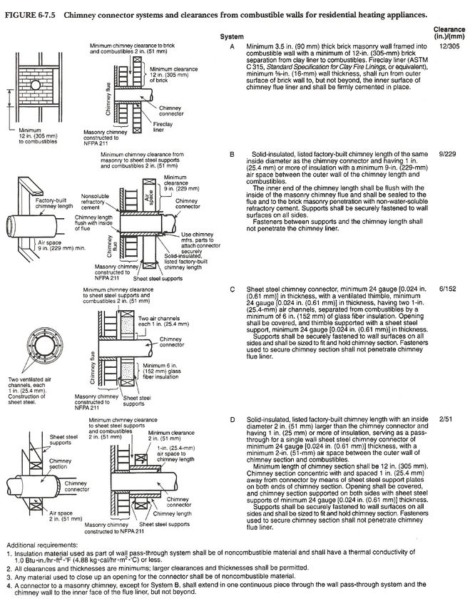
17DOOR ASSEMBLY
1
3
4 2
5
8
6
7
9
ID# Description Part Number ID# Description Part Number
1 Door spring, pewter KR SP 2P 4 Door pin w/retainer (2ea.) KR DP 2
1 Door spring, gold KR SP 2G 5 Door pin retainer (2 ea.) KR DP 2RT
2 Door casting: Black KR DR 1B 6 Glass gasket KR GK 34
2 Door casting: Pewter KR DR 1P 7 Glass (includes gasket) KR GL 1
2 Door casting: Gold KR DR 1G 8 Glass retainer (includes screws) KR GL 1RT
3 Door gasket kit KR GK 58 9 Glass retainer screw. Pack of 7 KR HW 4
18Section 6 – Clearances and diagrams
Figure #1 Double Wall Pipe
Use this diagram for the following installations:
1. Mobile Home installation with the stove in a corner using double wall pipe.
2. Residential installation with the stove in a corner using double wall pipe. For single wall pipe,
refer to figure 2.
4.5
13
6
6
4.5
16
13
6
Hearth
ALL CLEARANCES SHOWN IN INCHES
ALL CLEARANCES ARE MINIMUMS
HEARTH CLEARANCES SHOWN IN
19Figure #2 Single Wall Pipe
Use this diagram for the following installation:
1. Residential installation with the stove in a corner using single wall pipe. For double wall pipe,
refer to figure 1. For mobile home installation in a corner, refer to figure 1
9.5
18
6
6
9.5
16
18
6
Hearth
ALL CLEARANCES SHOWN IN INCHES
ALL CLEARANCES ARE MINIMUMS
HEARTH CLEARANCES SHOWN IN
20Figure #3 Double Wall Pipe
Use this diagram for the following installations:
1. Mobile home installation with the stove on a straight wall using double wall pipe.
2. Residential installation with the stove on a straight wall using double wall pipe. For single wall
pipe, refer to figure 4.
6
6 8.5
27
18
6 6
16
Hearth
ALL CLEARANCES SHOWN IN INCHES
ALL CLEARANCES ARE MINUMUMS
HEARTH CLEARANCES SHOWN IN
21Figure #4 Single Wall Pipe
Use this diagram for the following installations:
1. Residential installation with the stove on a straight wall using single wall pipe. For double wall
pipe, refer to figure 3. For mobile home installation on a straight wall, refer to figure 3.
15.5
6 18
27
18
6 6
16
Hearth
ALL CLEARANCES SHOWN IN INCHES
ALL CLEARANCES ARE MINIMUMS
HEARTH CLEARANCES SHOWN IN
22Tamarack installation diagram for manufactured chimneys.
NEVER INSTALL A WOOD STOVE IN A SLEEPING ROOM
Residential or Residential Home
manufactured home Installation
Installation
Spark arrestor
cap
2’ minimum
Roof brace
3’ minimum 10’
Storm collar
Flashing
ATTIC
Chimney
Sections
Wall support
2” MINIMUM 2” MINIMUM
Attic
Insulation air space around air space around
Shield
chimney chimney
Tee Support
Support
Box
Chimney
Tee with
cleanout
Cross Framing Double Wall
Connector
Double
Wall
Connector Wall Thimble
with horizontal
chimney
section must
extend 5”
minimum into
room.
6” minimum 18” minimum
4” outside
4” outside air vent
air vent
These diagrams are for manufactured chimneys. For Brick Chimneys a safety listed thimble must be used
when a connection is made through a combustible wall to a lined masonry chimney. This stove may be
connected to a lined masonry chimney or a listed factory built chimney designed for use with solid fuels
and conforming to, Canadian ULC629 or USA UL-103HT. Clearances to combustibles must be maintained
per manufacturer’s instructions on chimney pipe, and stove pipe connectors. Use only double-wall
connector in mobile homes
23Dimensional Drawings for the Tamarack
6”
9.5x12
31.25”
11”
21.5”
23.75” 5.5”
30.25”
10”
24Section 7 – Trouble Shooting
1. Stove burns lazy at start up.
2. Stove back-puffs or smokes into the room at start up.
3. Stove smokes out the door when it is open.
4. Stove won’t shut down.
5. Stove won’t burn hot enough. Lazy burn.
6. Burn time too short.
Stove burns lazy at start up.
1. The chimney is still cool, allow more time to warm up.
2. Wood is not seasoned (still green). Wood should sit for about 1 year, split and loosely stacked if it
was cut green.
3. Wood is well seasoned but has a lot of surface moisture. Your wood supply must be covered.
Check your tarps or other covering to see that no rain or snow is getting to your wood. Wood
should be covered on top, but open on the sides to allow air movement to aid in drying.
4. Check the air supply to the stove. If you have installed outside air, check the ducts for blockage.
If you are not using outside air, be sure you have removed the cover plate on the back of the
pedestal. (pedestal models only)
Stove back-puffs or smokes into the room at start up.
1. Chimney is cold. Cold chimneys can produce a “reverse draft” where cold air is rushing down the
chimney into the stove. Open a door or a window for about 5 minutes to equalize pressure in the
house then try restarting with small strips of newspaper. Using small strips of newspaper or an
approved fast burning fire starter and small pieces of kindling will create heat faster to help
reverse the cold air.
2. Chimney and/or the chimney cap needs to be cleaned. Your chimney should be checked and
cleaned if necessary every few months. Even a small amount of build up can cause a draft
restriction, for example: ¼ inch of build up on the side wall of a 6” chimney reduces the effective
area of the chimney by about 20%. Pay close attention to the chimney cap, especially if it has a
screen. Screened chimney caps can become blocked enough to restrict flow in just a few weeks.
Stove smokes out the door when it is open.
1. The door was opened too quickly. Crack the door open just a small amount and let the stove
“breathe” a few seconds before opening all the way.
2. Chimney and/or the chimney cap needs to be cleaned. Your chimney should be checked and
cleaned if necessary every few months. Even a small amount of build up can cause a draft
restriction, for example: ¼ inch of build up on the side wall of a 6” chimney reduces the effective
area of the chimney by about 20%. Pay close attention to the chimney cap, especially if it has a
screen. Screened chimney caps can become blocked enough to restrict flow in just a few weeks.
Stove won’t shut down.
1. The ash pan may not be sealing correctly. Check the ash pan gasket for tearing or fraying. See the
ash pan instructions in section 5. Even a small amount of undesired air can keep the stove from
shutting down.
2. Check the main door gasket and glass gasket for proper seal. See for instructions on checking
your gaskets.
Stove won’t burn hot enough. Lazy burn.
1. Wood is not seasoned (still green). Wood should sit for about 1 year, split and loosely stacked if it
was cut green.
252. Wood is well seasoned but has a lot of surface moisture. Your wood supply must be covered.
Check your tarps or other covering to see that no rain or snow is getting to your wood. Wood
should be covered on top, but open on the sides to allow air movement to aid in the drying.
3. Chimney and/or the chimney cap needs to be cleaned. Your chimney should be checked and
cleaned if necessary every few months. Even a small amount of build up can cause a draft
restriction, for example: ¼ inch of build up on the side wall of a 6” chimney reduces the effective
area of the chimney by about 20%. Pay close attention to the chimney cap, especially if it has a
screen. Screened chimney caps can become blocked enough to restrict flow in just a few weeks.
4. Check the air supply to the stove. If you have installed outside air, check the ducts for blockage.
If you are not using outside air, be sure you have removed the cover plate on the back of the
pedestal. (pedestal models only)
5. Atmospheric conditions. Occasionally, barometric episodes occur that affect draft, thereby
affecting stove performance. If your stove has been working fine and performance drops
suddenly, this is most likely the cause, and will usually go away within a few days.
6. Your fuel load may be too small or the wood size too large for the coal bed. A small bed of coals
requires re-kindling to build up the heat, only put large chunks of wood on a very hot and active
bed of coals.
Burn time too short.
1. Your fuel load may be too small or the wood size too large for the coal bed. A small bed of coals
requires re-kindling to build up the heat, only put large chunks of wood on a very hot and active
bed of coals. If there are large chunks of charred wood left after the fire has gone out, the coal bed
was not hot enough.
2. Fuel quality. Harder, denser woods produce longer burn times. Likewise, softer woods produce
shorter burn times.
3. The ash pan may not be sealing correctly. Check the ash pan gasket for tearing or fraying. See the
ash pan instructions in section 5. Even a small amount of undesired air can keep the stove from
shutting down.
4. Check the main door gasket and glass gasket for proper seal. See section 5 for instructions on
checking your gaskets.
26Section 8 – Accessories and Parts
Accessories
1. KA BL 1- Stove blower.
2. KA OA 1- Outside air kit.
3. KA LG SB- Black steel leg set.
4. KA LG CB- Black cast iron leg set.
5. KA LG CG- Gold plated leg set.
6. KA LG CP- Pewter plated leg set.
7. KA PK 2- Pedestal kit. Includes: ash pan system with ash grate.
8. KA SB 1- Decorative window sunburst, painted black.
9. KA DR 1B- Complete black door. Includes: Glass, glass holder, gaskets, door handle and door
pins.
10. KA DR 1G- Complete gold door. Includes: Glass, glass holder, gaskets, door handle and door
pins.
11. KA DR 1P- Complete pewter door. Includes: Glass, glass holder, gaskets, door handle and door
pins.
Parts
1. KR AG- Replacement ash grate
2. KR GK 58- Replacement 5/8 rope gasket
3. KR BR- Replacement Standard firebrick.
4. KR GL 1- Replacement glass, includes gasket.
5. KR GK 34- Replacement glass gasket
6. KR GL RT1- Glass retaining ring, includes new screws.
7. KR HW 4- Set of 7 glass retaining ring screws.
8. KR SP 1G- Gold ash pan or air control handle.
9. KR SP 1P- Pewter ash pan or air control handle.
10. KRSP 2G- Gold door handle
11. KR SP 2P- Pewter door handle
12. KR BT TM- Baffle burn tube.
13. KR IN TM- Ceramic baffle insulation.
14. KR BF TMT - Rear baffle brick holder
15. KR BF TMZ - Front baffle brick holder.
27Section 9 – The Kuma “It’s Covered” Limited Warranty
Our Promise:
If anything goes wrong with your stove in the first three years, we will supply you with the parts to fix it.
For as long as you own your stove, if you ever have a defect in the material or workmanship of your stove’s
firebox, we will repair or replace it for you. See full details below:
Items Covered Parts Coverage Period Labor Coverage Period
Maintenance Items: Bricks, 3 Years No Labor Coverage
gasket, ceramic insulation, baffle
boards and paint.
Glass (thermal breakage), 5 Years 3 Years
blowers, ash grate, brick
supports, all hardware and trim.
Stove firebox, ash pan, pedestal, Forever 3 Years
legs, burn tubes and door casting.
Warranty Coverage:
To ensure warranty coverage, it is very important that you register your Kuma Stove warranty within 30
days of purchase at kumastoves.com or fill out and return the warranty registration in your owners
packet. This warranty covers your new Kuma Stove from defects in material and workmanship for the
period outlined in this warranty. Kuma Stoves reserves the right to replace, repair or authorize repair of
any defective part at its sole discretion. This warranty is not transferrable and covers the original owner of
the product from the time of purchase. All parts that have been replaced under this warranty will have a 90
day warranty coverage. The maximum value of this warranty is the original purchase price of the product.
This warranty is subject to the conditions and limitations outlined below. This warranty covers stoves
purchased from an authorized Kuma Stoves dealer.
Warranty Instructions:
For your “It’s Covered” warranty claim, please contact the dealer where you purchased your stove. You
may also contact Kuma stoves directly at 1-888-714-5294 or contact us online at kumastoves.com. When
calling, you will need to have your proof of purchase, the model name, and the serial number of your stove.
When calling please remember that shipping and handling costs are not covered under this warranty.
Warranty Exclusions:
This Warranty does not cover: 1. Changes in the color of the surface of the stove as this naturally happens
during the firing of the stove and is considered normal. 2. Damage to plating due to chemical cleaners,
fingerprints, or scratching. 3. Shattered glass caused from wood impact. 4. Discoloration of plating or
glass. 5. Expansion and contraction of the firebox causing noise. 6. Damage caused from: power surges,
unauthorized modifications, using incorrect fuel and/or accelerants, shipping/handling, failure to follow the
manufacturer’s installation instructions, failure to follow any local building codes. 7. Damages to any
product not manufactured by Kuma Stoves. 8. Any stoves ability to heat a specific area. Heating capacity
is given as a guideline and is not guaranteed. 9. Shipping costs or travel time. Please talk with an
authorized dealer or Kuma representative about the potential charges for travel or shipping. 10. This
warranty is void in the case of abuse, over firing, unauthorized repair, alterations, improper installation
and/or service.
Effective 3/1/20
28You can also read