Development of a Wall-Sticking Drone for Non-Destructive Ultrasonic and Corrosion Testing - MDPI
←
→
Page content transcription
If your browser does not render page correctly, please read the page content below
drones
Concept Paper
Development of a Wall-Sticking Drone for
Non-Destructive Ultrasonic and Corrosion Testing
Rami A. Mattar *      ID
                           and Remy Kalai
 Department of R&D, Amerapex Corporation, Houston, TX 77092, USA; rkalai@amerapex.com
 * Correspondence: rmattar@amerapex.com; Tel.: +1-713-263-0900

 Received: 23 January 2018; Accepted: 21 February 2018; Published: 24 February 2018

 Abstract: Refineries’ structures require constant inspection, maintenance of their structural health
 condition, and safety of the users; however, accessing these structures is getting more and more
 difficult due to their enormous height and size. In order to deal with this problem, many researchers
 have developed several robots for wall crawling, yet there is no guaranteed solution. One of the
 critical reasons why existing wall-crawling robots have not been available in the field is the risk
 of accidental fall due to operational failure from the harsh environment, like strong wind and the
 surface’s unpredictable condition. Therefore, we attempted to develop a wall-sticking aerial robot
 platform that can approach any place of the structure by flying and sticking to the target place. The
 robot is equipped with electro-magnetic hold mount elements to stick the sensor probe on the surface
 of the structure. This paper deals with installing the wall-sticking mechanism on the aerial robot.

 Keywords: drone; nondestructive testing; NDT; wall-sticking; UAV; contact based inspection

1. Introduction
       Drones have become increasingly autonomous with their services and usability. Drones started as
a consumer and hobbyist phenomenon, but more recently they have grown into the field of remote
visual inspection of industrial assets and sensing and other enterprise use cases. According to [1],
last year alone, drone startups saw more than $450 million of investments. It is a great addition to
the inspection methods that are utilized at the moment in the inspection industry. Drone inspections
are innovative inspection methods. The customer demand is growing rapidly and the possibilities
are developing daily. Demand is significantly higher for military applications, although commercial
applications are gradually catching up.
       While non-contact-based drone inspection, such as visual, optical, IR, LIDAR, and gas detectors
etc., is moving quickly to a commodity business, significant efforts are still to be made in aerial robotics
and nondestructive testing (NDT) measurement technology to access conventional contact NDT, such
as ultrasound testing (UT) and eddy-current testing (ECT).
       There are only a few studies available where drones are utilized to monitor structures, which are
only visual and image processing-based methods.
       The objective of the project is to develop breakthrough industrial inspection solutions integrating
the most recent robotics technologies. In the most challenging deliverables of the project, the consortium
will deliver industrial aerial robots able to perform contact NDT, such as UT and ECT, leveraging the
miniaturized, wireless inspection technologies of Amerapex NDT Inspection, Houston, TX, USA.
       Aboveground storage tanks throughout their operating life are subjected to considerable
operational and environmental forces, and subject to corrosion and cracks on the surface and subsurface
level that travel parallel to the surface.
       Usually cranes, scaffolds, rope-access, and people are used to inspect both the storage tanks and
the overall structure. Maintenance and inspection are, thus, costly, time consuming, and risky for those
who carry out the inspection. The solution to this can be to let autonomous drones do the work.

Drones 2018, 2, 8; doi:10.3390/drones2010008                                   www.mdpi.com/journal/drones
Drones 2018, 2, 8                                                                                                                   2 of 11

                 Drones 2018, 2, x FOR PEER REVIEW                                                                  2 of 11

     Inspection Usually
                  robotscranes,
                            play scaffolds,
                                   an important      part
                                            rope-access, andin  the are
                                                             people   oilused
                                                                          andtogas     industry
                                                                                  inspect           by taking
                                                                                          both the storage        the invaluable
                                                                                                           tanks and
role of inspection,  monitoring,
             the overall             and surveillance
                         structure. Maintenance              of complex
                                                 and inspection               structures
                                                                  are, thus, costly,         in the industries,
                                                                                     time consuming,   and risky forand, thereby,
averting any those who carry out the inspection. The solution to this can be to let autonomous drones do the
              disasters   that may occur. The use of robots help in reducing human intervention, increase
             work.
operational efficiency,    reducing
                  Inspection           costs,
                             robots play       and improving
                                         an important                safety.
                                                        part in the oil and gas industry by taking the invaluable
                 role of inspection, monitoring, and surveillance of complex structures in the industries, and, thereby,
2. Concept of a Wall-Sticking
            averting               Drone
                     any disasters that may          occur. The use of robots help in reducing human intervention,
                 increase operational efficiency, reducing costs, and improving safety.
     Wall sticking of the aerial robot can be accomplished by the combination of the thrust force and
wheel drive 2.    Concept of a Wall-Sticking Drone
               force   with maximized friction between the drone wheel and the surface [2,3]. However
                     Wall
the authors of this paper  stickinghave
                                     of the demonstrated
                                             aerial robot can be accomplished     by the combination
                                                                   the wall sticking                   of the thrustaerial
                                                                                            of an unmanned           force and
                                                                                                                             vehicle by the
               wheel drive force with maximized friction between the drone wheel and the surface [2,3]. However
combination the of the
                    authors of this paper have demonstrated the wall sticking of an unmanned aerial vehicle by themetal surface.
                        thrust     force    and    electromagnetic         force  to press   the   sensor   probe    on  the
If the frictioncombination
                  coefficient      is higher
                               of the  thrust forcethan
                                                      and 1,   the robot can
                                                            electromagnetic   forcestick   to the
                                                                                    to press   thesensor
                                                                                                    vertical
                                                                                                          probesurface     with the thrust
                                                                                                                 on the metal
               surface. If  the friction  coefficient  is higher  than 1, the robot can
force toward the wall [4,5]. The authors have investigated this mechanism using a simplestick to the vertical surface with  the   tri-copter
               thrust force toward the wall [4,5]. The authors have investigated this mechanism using a simple
and conducted       outdoor      experimental          tests.   Figure    1 describes     the   principle    of the
               tri-copter and conducted outdoor experimental tests. Figure 1 describes the principle of the drone     drone    wall-sticking
mechanism in       the industrial
               wall-sticking   mechanism structure      space.structure space.
                                              in the industrial

                                 Figure 1. Diagram of an implementation of the system on a refinery tank farm.
                    Figure 1. Diagram of an implementation of the system on a refinery tank farm.
                 3. System Description
3. System Description
               The contact-based        drone inspection was studied to evaluate the possibility of conducting
             ultrasonic thickness testing at random spots on structures that are not immune to corrosion and
     The contact-based
             material degradingdrone     inspection
                                    due to processes and wasotherstudied     to evaluate
                                                                   environmental              theaspossibility
                                                                                    impacts, such   storage tanks of
                                                                                                                   in conducting
ultrasonic thickness      testing
             refineries and          at random
                              petrochemical   plants.spots    on structures
                                                      It is meant   for attaching that  are notsensor
                                                                                   the ultrasonic  immune
                                                                                                        probe to   corrosion and
                                                                                                               to an
             open-source robotics vehicle platform (see Figure 1).
material degrading       due to processes and other environmental impacts, such as storage tanks in
                  While designing the system, the primary design objectives kept in mind are: ease of use,
refineries and   petrochemical
             modularized               plants. ofItsensors,
                            for fast deployment       is meant       fordata
                                                             real-time    attaching     the
                                                                             display and,     ultrasonic
                                                                                           most importantly,sensor
                                                                                                             meet the probe to an
open-source safety
             roboticscodesvehicle    platform
                           and regulations       (see Figure
                                            for hazardous         1).
                                                            environments.
                  The drone is a vertical take-off and landing, or VTOL, vehicle. It was selected from a set of
     While designing         the system, the primary design objectives kept in mind are: ease of use,
             criteria that met our needs:
modularized for fast deployment of sensors, real-time data display and, most importantly, meet the
safety codes and regulations for hazardous environments.
     The drone is a vertical take-off and landing, or VTOL, vehicle. It was selected from a set of criteria
that met our needs:

1.     Cost and availability.
2.     Spare-parts and reparability.
3.     Open-source hardware and software.

3.1. Frame Design
     The UAV is a tri-copter and the goal is that the yaw functions differently. The rear motor pivots
giving yaw more like a helicopter instead of like a quad-copter, which uses differential torque to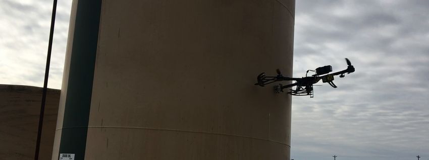
1.    Cost and availability.
                 2.    Spare-parts and reparability.
                 3.    Open-source hardware and software.

                 3.1. Frame Design
                  Drones 2018, 2, 8                                                                                      3 of 11
                      The UAV is a tri-copter and the goal is that the yaw functions differently. The rear motor
                 pivots giving yaw more like a helicopter instead of like a quad-copter, which uses differential torque
                  achieve
                 to achieveyaw.
                             yaw.Differential
                                  Differentialtorque
                                                torqueisismuch
                                                           muchweaker
                                                                 weakerand
                                                                         andslower.
                                                                              slower. ItIt works
                                                                                           works assuming  that the
                                                                                                 assuming that  the system
                                                                                                                    system isis
                  basically in balance  and only   a slight change  in torque  will yield   yaw. Pivoting the rear motor
                 basically in balance and only a slight change in torque will yield yaw. Pivoting the rear motor will    will
                  yield more
                 yield  more powerful
                              powerful yaw
                                         yaw control
                                              control (see
                                                       (see Figure
                                                            Figure 2).
                                                                   2).

                                 Figure 2. NDT ultrasonic testing UAV system overview.

 The main materials of the UAV frame are carbon fiber plates. The selection of motors was b
he frame size, propeller size, battery capacity, and motor drive. Figure 3 shows the UAV ge
 m block diagram.
 The UAV itself was designed around this application. The tri-copter has much more “y
rol than a standard quad and it handles the wind conditions much better. Secondly, the forw
 on is not significantly different; the yaw is the difference. Thirdly, the overall cost o
                                        Figure 2. NDT ultrasonic testing UAV system overview.
ame is about the same as a quad-copter,                      because
                                         Figure 2. NDT ultrasonic   testingthe    extraoverview.
                                                                            UAV system     servo and mechanism for yaw is a
 ame price as anThe  extra
                    The  main
                              motor
                        main materials
                              materials
                                        setup.
                                       of
                                        of
                                           the UAV
                                            the UAV
                                                    The
                                                      framerest
                                                       frame  are
                                                                   of the
                                                             are carbon
                                                                  carbon
                                                                              frame
                                                                          fiber
                                                                           fiber plates.
                                                                                         is
                                                                                 plates. The
                                                                                         The
                                                                                            not    that
                                                                                             selection
                                                                                              selection
                                                                                                           different
                                                                                                        of motors
                                                                                                        of motors
                                                                                                                       from a quad-co
                                                                                                                  was based
                                                                                                                  was based
             on the frame size, propeller size, battery capacity, and motor drive. Figure 3 shows the UAV           general
 less leg doessystem
               onnot   appreciably
                  the frame
                      block               change
                            size, propeller
                            diagram.                     thecapacity,
                                             size, battery    material        costs.
                                                                      and motor     drive. Figure 3 shows the UAV general
                  system
                      Theblock
                           UAVdiagram.
                                 itself was designed around this application. The tri-copter has much more “yaw”
                 control than a standard quad and it handles the wind conditions much better. Secondly, the forward
                 motion is not significantly different; the yaw is the difference. Thirdly, the overall cost of the
                 airframe is about the same as a quad-copter, because the extra servo and mechanism for yaw is about
                 the same price as an extra motor setup. The rest of the frame is not that different from a quad-copter.
                 One less leg does not appreciably change the material costs.

                                                 Figure 3. UAV general system block diagram.

                                             Figure 3. UAV general system block diagram.
                                      Figure 3. UAV general system block diagram.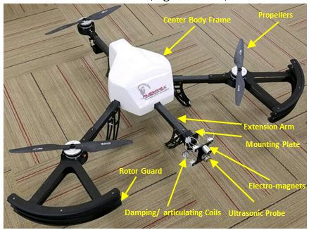
Drones 2018, 2, 8                                                                                                             4 of 11

     The UAV itself was designed around this application. The tri-copter has much more “yaw” control
than a standard quad and it handles the wind conditions much better. Secondly, the forward motion is
not significantly different; the yaw is the difference. Thirdly, the overall cost of the airframe is about
the same as a quad-copter, because the extra servo and mechanism for yaw is about the same price as
an extra motor setup. The rest of the frame is not that different from a quad-copter. One less leg does
not appreciably change the material costs.
     Interchangeable sensor modules were attached to the platform. Sensor data was relayed through
the flight computer via a wireless telemetry link to the ground station app. The ground station
application software displays the sensor data in real-time.
     It consists of Y Copter access panel (S), tri copter battery tray, landing gear plates, Y Copter frame,
           Drones 2018, 2, x FOR PEER REVIEW                                                                         4 of 11
Motor mount      for pivoting motor, M3 and M4 lock nut retainer plates, servo mount, stationary                                motor
mounts, servoInterchangeable
                  mount carbonsensor    tab (ENV),       GPS    sensor, 16,000    mAH     battery,  receiver/transmitter
                                                modules were attached to the platform. Sensor data was relayed                 for RC,
ESC's for motors,      and    a  Pixhawk       control    module.
           through the flight computer via a wireless telemetry link to the ground station app. The ground
           station application
     The platform        supportedsoftware    displaysand
                                         a simple        the sensor data in real-time.
                                                              expandable      interface for attaching custom sensors to the
                It consists of Y Copter access panel (S), tri copter battery tray, landing gear plates, Y Copter
drone, overcoming the limitation of single-purpose platforms which are costly to convert for other
           frame, Motor mount for pivoting motor, M3 and M4 lock nut retainer plates, servo mount, stationary
tasks. Since  themounts,
           motor    sensorservo system
                                     mount is carbon
                                              modularized,
                                                       tab (ENV), sensors
                                                                   GPS sensor,can  be exchanged
                                                                                16,000 mAH battery, rapidly.     In addition to the
                                                                                                      receiver/transmitter
hardware forplatform,
               RC, ESC'swhich        easily
                             for motors,  and integrates       sensors,
                                                a Pixhawk control         it is possible to use an established open-source
                                                                    module.
infrastructureThe     platformsensor
                  to collect      supportedprobea simple
                                                     dataand   expandable
                                                            from   the droneinterface for attaching
                                                                                in real-time.       custom
                                                                                                  The  drone sensors
                                                                                                                needtonot
                                                                                                                        the be visible
           drone, overcoming the limitation of single-purpose platforms which are costly to convert for other
to the operator, but some line-of-sight is, however, required to ensure the signal is not dropped and
           tasks. Since the sensor system is modularized, sensors can be exchanged rapidly. In addition to the
real-time data    lost.platform, which easily integrates sensors, it is possible to use an established open-source
           hardware
     The sensor     gaugetomodule
           infrastructure                  withprobe
                                collect sensor      its transceiver
                                                         data from the unit
                                                                       droneisinfitted  inside
                                                                                 real-time.      the canopy
                                                                                            The drone   need notand  it can be fitted
                                                                                                                 be visible
           to theinoperator,
to the bracket       variousbutways.
                                   some line-of-sight
                                           It will not is,   however,with
                                                           interfere   required
                                                                             the to ensure theintegrity
                                                                                  structural    signal is not
                                                                                                           ofdropped   and as long as
                                                                                                               the drone
           real-time data lost.
the module is kept within certain physical limits.
                 The sensor gauge module with its transceiver unit is fitted inside the canopy and it can be fitted
            to the bracket in various ways. It will not interfere with the structural integrity of the drone as long
3.2.   Mechanism   of Wall-Sticking
            as the module is kept within certain physical limits.
     The UAV      has a capacity of hovering like most common drones, and is manually controllable
           3.2. Mechanism of Wall-Sticking
by a remote operator by means of a remote control, or operate partially automated. It restrains a
                 The UAV has a capacity of hovering like most common drones, and is manually controllable by
fixed extension    arm that extends far from the neighboring blades with a mounting plate that contains
           a remote operator by means of a remote control, or operate partially automated. It restrains a fixed
compact and     lightweight
           extension  arm that articulating
                                extends far fromflexible   coils (seeblades
                                                     the neighboring     Figure   4). a mounting plate that contains
                                                                                with
     During    a data
           compact     acquisition
                     and lightweight by   the drone,
                                      articulating       it may,
                                                    flexible        for Figure
                                                             coils (see example,
                                                                               4). based on the accuracy of the steering
and hoveringDuringby thea operator,
                           data acquisition
                                       and/or by the   drone,the
                                                    under      it may,
                                                                   effectforof
                                                                             example,
                                                                               a side based
                                                                                        windonorthe accuracy of
                                                                                                  a stream    of the
                                                                                                                 air, undergo
           steering and hovering by the operator, and/or under the effect of a side wind or a stream of air,
rotational undergo
            movements       about   its  axis  of   pitch,  such    as  vertical  movement      (up  or down)
                     rotational movements about its axis of pitch, such as vertical movement (up or down)
                                                                                                                  and/or side
movementand/or
             (rightside
                     ormovement
                        left).     (right or left).

                                               Figure 4. The drone and its components.
                                          Figure 4. The drone and its components.
                   Such events may cause the detachment or removal of the drone’s sensor probe from the surface
              under testing and prevent it from taking the inspection readings. According to an optional feature of
              the invention, the articulating joint or (coil) may assist in absorbing the impact when the UAV flies
              directly to the surface of interest and lands on the probe side (front side of the UAV) to stick on it. By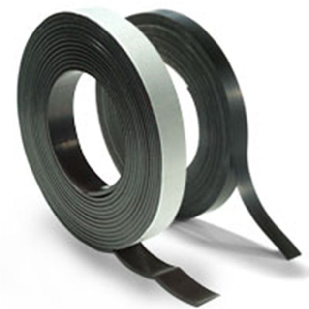
Drones 2018, 2, x FOR PEER REVIEW 5 of 11
the combination of the thrust force generated by the UAV and the electromagnet units that surround
Drones 2018, 2, 8 5 of 11
the probe, the pressurization of the sensor probe against the surface will be achieved. The motors are
AC brushless motors that offer high torque and efficiency.
Such events may cause the detachment or removal of the drone’s sensor probe from the surface
Front rotor
underguards
testing andareprevent
designedit fromto protect
taking them from
the inspection contact
readings. withtothe
According wall, which
an optional feature isof also made
from carbonthe fiber. The the
invention, ultrasonic
articulating probe
joint ortakes a measurement
(coil) may assist in absorbingwhen applied
the impact whenagainst
the UAV afliessurface. It is
directly to the surface of interest and lands on the probe side (front
held stationary for a few seconds (1 to 2 s) for a measurement to be taken. This allows measuring side of the UAV) to stick on it. of
By the combination of the thrust force generated by the UAV and the electromagnet units that surround
the thicknesstheofprobe,
the themetal surface under examination per the ASNT ‘Ultrasonic Testing Standards
pressurization of the sensor probe against the surface will be achieved. The motors are
and Practices’.
ACThe ultrasonic
brushless probe
motors that offer induces
high torque a and
normal beam ultrasonic signal that travels through the
efficiency.
Front rotorand
surface and subsurface, guards
thearereflected
designed to protectfrom
signal them thefromback
contact with theis
surface wall, which isby
detected alsothe
made probe and is
from carbon fiber. The ultrasonic probe takes a measurement when applied against a surface. It is
converted to a digital reading of the thickness of the part underneath the probe.
held stationary for a few seconds (1 to 2 s) for a measurement to be taken. This allows measuring
The testofwas initiallyofconducted
the thickness the metal surface with theexamination
under sensor onboard without
per the ASNT any kind
‘Ultrasonic Testingof magnet. Then, to
Standards
keep it fromand moving
Practices’.onThethe surface,
ultrasonic probewe added
induces a small
a normal permanent
beam ultrasonic signalmagnet.
that travels However,
through the the basic
surface and subsurface, and the reflected signal from the back surface is detected by the probe and is
concept of just pushing against the surface with the drone will work without the drone immediately
converted to a digital reading of the thickness of the part underneath the probe.
hovering uncontrollably.
The test wasThe controls
initially conductedeventually had an
with the sensor issuewithout
onboard because anyof theof heading
kind magnet. Then,component in
the control logic.
to keep This shows
it from movinguponinthe thesurface,
rudder/yaw
we addedperforming the wrong
a small permanent magnet. move
However,a few times. The last
the basic
concept of just pushing against the surface with the drone will work without
time it was disconnected from the wall to prevent any further issues. To make this work long-term a the drone immediately
hovering uncontrollably. The controls eventually had an issue because of the heading component in
decision hasthebeen made to modify the flight control code to put it in a “rate” gyro mode when
control logic. This shows up in the rudder/yaw performing the wrong move a few times. The last
pushing against
time itthe
waswall. This would
disconnected from the prevent a buildup
wall to prevent of issues.
any further control and this
To make allowworkthe dronea to steadily
long-term
push againstdecision
the wallhas been made to modify
without the flight control
any significant code to
issue. Weputtested
it in a “rate”
withgyroa mode
light,when pushingpermanent
flexible
against the wall. This would prevent a buildup of control and allow the drone to steadily push against
magnet (shown in Figure 5), suggesting it might work. Its adhesive force is 32 lbs., has a width of 1”,
the wall without any significant issue. We tested with a light, flexible permanent magnet (shown in
and it weighs 3.3 oz.
Figure 5), suggesting it might work. Its adhesive force is 32 lbs., has a width of 1”, and it weighs 3.3 oz.
FigureFigure
5. The flexible
5. The flexiblemagnetic material.
magnetic material.
The flexibleThemagnetic material
flexible magnetic was was
material wrapped
wrappedaround the
around the mount
mount frameframe of theasprobe,
of the probe, shown in as shown in
Figure 6. However, the test flight shows we can push the UAV against the wall and it stays relatively
Figure 6. However, the test flight shows we can push the UAV against the wall and it stays relatively
stable without the permanent magnet. The permanent magnet did not show any significant help to
stable without the the
sticking permanent
probe on themagnet.
wall, as weThe permanent
determined that the magnet did not
magnet’s surface show
contact area any
is notsignificant
sufficient help to
sticking the enough
probetoon the wall,
generate as we
the needed determined
traction that the
force. The effective magnet’s
force surface contact
would be generated by a largerarea is not
permanent
sufficient enough magnet, butthe
to generate thatneeded
will be bulky and heavy,
traction hence,
force. The noteffective
feasible forforce
this purpose.
would be generated by a
larger permanent magnet, but that will be bulky and heavy, hence, not feasible for this purpose.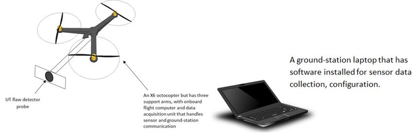
Drones 2018, 2, x FOR PEER REVIEW 6 of 11
Drones 2018, 2, 8 6 of 11
Drones 2018, 2, x FOR PEER REVIEW 6 of 11
Figure 6. The flexible magnetic material wrapped around the probe mount.
theFigure
To achieve Figure 6. The flexible magnetic material wrapped around the probe mount.
sticking force magnetic
6. The flexible and stationary level needed
material wrapped aroundto thetake
probea mount.
reliable reading, two
electromagnets (EM) are suggested. EM combines the advantages of electro-
To achieve the sticking force and stationary level needed to take a reliable reading, two
and permanent
magnets.
To achieve the
electromagnets (EM) sticking force and
are suggested. EM stationary
combines the level neededoftoelectro-
advantages take aandreliable
permanent reading,
Each EM used
two electromagnets
magnets. is a round design that provides adhesive forces of up to 120
(EM) are suggested. EM combines the advantages of electro- and permanent magnets.lbs. They are made of
a zinc-plated
EachEach
EM EMcase,
used 1.5’’
used
is adiameter
aisround
rounddesign× 1.5’’
designthat long − weight
thatprovides
provides 10 forces
adhesive
adhesive oz. The
forces of electrical
ofup
up toto120
120 specifications
lbs.
lbs.They areare
They made are:
made #20a
of of
AWG a lead wires
zinc-plated ×
case, 24’’
1.5’’long outside
diameter × of
1.5’’ the
long −magnet,
weight 12
10 VDC,
oz. The 4.0 watts,
electrical and 100%
specifications
zinc-plated case, 1.5” diameter × 1.5” long − weight 10 oz. The electrical specifications are: #20 AWG duty
are: #20 cycle
lead AWG
standards.
wires ×lead
24”wires
long ×outside
24’’ long outside
of the of the
magnet, 12magnet,
VDC, 4.012watts,
VDC, and
4.0 100%
watts, duty
and 100% duty cycle
cycle standards.
standards.
The device creates
createsaavery verystrong
strong magnetic contact with a ferrous target,
The device magnetic contact with a ferrous target, and and it supports
it supports the
the UAV
UAV and The
RC device
remote creates
control.a very strong magnetic contact with a ferrous target, and it supports the
and RC remote control.
UAV and RC remote control.
-- AnAn
ON
- AnONcommand results
ONcommand
commandresults
inin
achieving
results in achieving
achieving
full magnetization.
full
full magnetization.
magnetization.
-- An OFF
-AnAn
OFF command
OFFcommand results
commandresults in releasing
results in releasing
releasing oror
orunsticking
unsticking
unsticking the
the
the unit
unit
unit from
from
from thethe
the surface.
The The
surface.
surface. The ultrasonic
ultrasonic
ultrasonic
probe
probe and
probe both
andand EMs
both
both EMsEMsare
are housed
are housedin
housed ininone
one aluminum
one plate,
plate,asas
aluminum plate,
aluminum shown
shown
as shown in
in Figure
in Figure 7.
7. 7.
Figure
(a)
(a)
(b)
Figure 7. (a) EM schematic, and (b) the ultrasonic probe and EMs with the articulating joint design.
(b)
Figure 7. (a) EM schematic, and (b) the ultrasonic probe and EMs with the articulating joint design.
Figure 7. (a) EM schematic, and (b) the ultrasonic probe and EMs with the articulating joint design.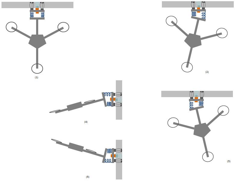
Drones 2018, 2, x FOR PEER REVIEW 7 of 11
TheDrones
ultrasonic
2018, 2, 8 thickness gauge is a commercial off-the-shelf unit that is designed 7for of 11common
thickness gauging applications with the added benefit of being able to store measurements within
the gauge. All ultrasonicthickness
The ultrasonic thickness
gaugegauges should off-the-shelf
is a commercial be calibrated to the
unit that velocity
is designed forof sound of the
common
material being measured. Coatings have a different velocities of sound than metal and it is important
thickness gauging applications with the added benefit of being able to store measurements within
they arethe
notgauge.
included All ultrasonic thickness gauges
in the measurement. should echo
Multiple be calibrated
ensurestoallthecoatings,
velocity ofupsound
to 6 mmof thethick, are
material being measured. Coatings have a different velocities of sound than metal and it is important
completely eliminated from the measurement. The probe used is a 2.25 MHz probe that works well
they are not included in the measurement. Multiple echo ensures all coatings, up to 6 mm thick,
on heavily-corroded metal. Its from
are completely eliminated resolution and accuracy
the measurement. are 0.1
The probe mm
used is a (0.005
2.25 MHz inch)
probeandthat±0.1 mm (0.005
works
inch), respectively. A transmitted
well on heavily-corroded metal.ultrasound
Its resolutionpulse travelsare
and accuracy though
0.1 mmboth(0.005the coating
inch) and ±0.1 andmm the metal
and reflects
(0.005from
inch), the back wall.
respectively. The returned
A transmitted echo
ultrasound then
pulse reverberates
travels though bothwithin theand
the coating metal, with only a
the metal
and reflects from the back wall. The returned echo then reverberates within
small portion of the echo travelling back through the coating each time. The timing between the metal, with only a the
small portion of the echo travelling back through the coating each time. The timing between the small
small echoes gives the timing of the echoes within the metal, which relate to the metal thickness. The
echoes gives the timing of the echoes within the metal, which relate to the metal thickness. The gauge
gauge will
willinterpret
interpret the the echoes
echoes automatically
automatically and calculate
and calculate theThe
the thickness. thickness.
measuringThe measuring
range of a 2.25 MHz range of a
2.25 MHz probe
probe goestodown
goes down to 3 ismm,
3 mm, which which
perfectly is perfectly
acceptable acceptableThis
in most applications. intechnique
most applications.
is referred This
technique is the
to as referred
automatic to as the automatic
measurement measurement
verification verification
system (AMVS) system
(see Figure 8). (AMVS) (see Figure 8).
Figure 8. The
Figure deployed
8. The deployedultrasonic probe
ultrasonic probe and
and testing
testing method.
method.
Lithium-ion batteries
Lithium-ion (16,000
batteries MAH)
(16,000 MAH)used used to powerthe
to power the system
system are lightweight,
are lightweight, and
and have have a large
a large
capacity, high discharge rate, and good energy storage to weight ratio.
capacity, high discharge rate, and good energy storage to weight ratio. The readings pickedThe readings picked up by up by
the sensor module are then relayed to a ground station using the telemetry modules; on the drone,
the sensor module are then relayed to a ground station using the telemetry modules; on the drone,
the radio link module is connected directly to the flight computer.
the radio link module is connected directly to the flight computer.
The author has attached a dry couplant to the probe for contact inspection. The dry couplant
The(elastomer)
author has attachedspecifically
is designed a dry couplant to theinspection
for ultrasonic probe for contact inspection.
applications. Unlike dryThe dry couplant
couplants
(elastomer) is designed
normally used as an specifically
integral part offor ultrasonic
ultrasonic probes,inspection applications.
this elastomer can be appliedUnlike dry couplants
independently
of the probe. Acoustic impedance of the material is nearly the same as water and
normally used as an integral part of ultrasonic probes, this elastomer can be applied independently its attenuation
coefficient is lower than all other documented elastomers and many plastics.
of the probe. Acoustic impedance of the material is nearly the same as water and its attenuation
coefficient is lower than
4. Discussion all other
of Related Workdocumented elastomers and many plastics.
As mentioned in the introduction, there were only a few studies available where drones are
4. Discussion
utilizedof Related
in the Work
inspection of structures, which are focused on visual inspections only. Many companies
are able to achieve NDT visual inspections using drones. Companies, such as Industrial Works,
As mentioned in the introduction, there were only a few studies available where drones are
are currently able to identify issues, like water accumulation, solar loading, and areas susceptible
utilized toinrust
theandinspection of structures,
corrosion, which which
cannot be seen by the are
humanfocused
eye. [6] on visual
These dronesinspections only. Many
are able to achieve
companies are able
the same to as
results achieve NDT
the drone visual
proposed byinspections using
the authors when drones.visual
performing Companies, such
inspections, yetas Industrial
they
Works, are
areunable
currently
to makeable to identify
contact issues,
inspections. like one
However, water accumulation,
company solar
has been able loading,
to achieve and areas
similar
susceptible to rust and corrosion, which cannot be seen by the human eye. [6] These drones are able
to achieve the same results as the drone proposed by the authors when performing visual
inspections, yet they are unable to make contact inspections. However, one company has been able
to achieve similar results as the drone manufactured by the authors. The Center for Advanced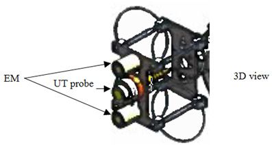
Drones 2018, 2, 8                                                                                    8 of 11

results as the drone manufactured by the authors. The Center for Advanced Aerospace Technologies
(CATEC), a technology company in Spain, has created a drone capable of making contact with surfaces
at altitude and using a probe to take measurements. The drone has similar features to hover at altitude.
The main difference is the mechanism to make contact with a surface. Where the drone created by
the authors uses electromagnets to make a strong connection with the surface, CATEC uses three
prongs to push into the surface and make contact. Comparing their drone with the proposed concept
will not make as strong a connection with the surface because of the proposed concept of utilizing
the power of the electromagnets rather than just pressure created by the drone. [7,8]. Ellenberg et al.
performed an investigation on remote sensing capabilities of a commercialized drone (Parrot AR
2.0) for crack detection from various distances [9]. An algorithm was developed for post-image
processing where a field test was conducted on a bridge in order to evaluate the performance of
the drone. Sankarasrinivasan et al. introduced an approach involving a combination of the Top-hat
transform and HSV (hue, saturation, and value) thresholding technique which is a tool for solving
clustering problems in image processing for detecting cracks, using a drone for a real-time SHM [10].
Another related work was executed by Vel Tech University in India. It was a field testing that was
conducted in an outdoor environment to evaluate the performance for the proposed study, during
existing factors, such as wind, and random image noises that resulted in a few inaccurate results.
Eschmann et al. used an octocopter for a building inspection where photos were taken at high speed
and frequency [11]. According to their study, more than 12,000 photos were taken over a four-day
period for an inspection of cracks on the target structure. Markus Eich et al. from the Robotics
Innovation Center at Bremen, Germany, have created a magnetic wall climbing robot that is capable of
attaching to ships in order to perform visual inspections. Their robot is able to reach heights exceeding
10 m [12]. Amit Shukla et al. also implemented the use of UAVs in detecting corrosion in oil and
gas pipelines [13]. This UAV is used in visual inspections of pipelines from low altitudes with the
intention of reducing the risk of having humans do these inspections. Lee et al. have developed a
crawling magnetic robot that can navigate in a tubular environment, and a magnetic pulley module
is utilized to generate a drilling motion to unclog blocked regions and uncover motions of a stent
cover for a self-expandable stent deployment [14]. Na et al. proposed and performed a concept of
converging a drone with a vibration-based non-destructive evaluation method [15]. Their technique
requires one to permanently attach a PZT transducer onto the surface of the target structure, usually in
10 mm square sizes. They used a PZT with a frequency range between 20 and 400 kHz, to examine the
mechanical impedance of the host structure. However, according to their findings, if the host structure
is non-metallic (e.g., concrete, composite, wood, etc.), a support permanent magnet must be attached
to the host structure permanently.

5. Test and Result
      The author initially used a simpler and smaller version of the tricopter for testing while fine-tuning
the flight control codes in order to minimize damage costs to the larger unit that is equipped with the
sensing device. The goal is to have the control logic used during normal flight to be the same as the
control logic that is used when the drone is against the wall.
      The author has initially conducted manual tests around the structure to collect data as a reference.
      The drone tests have shown that the drone takes off from the ground and hovers near the target
area with high stability, and sticks to it using the EMs and back pressure from the drone itself.
      As seen in the hovering scenarios in Figure 9, the different scenarios show how the drone would
maintain contact even with the existence of movement or instability due to high wind speed or other
mechanical instability. The EM is powerful enough to hold the drone, and it has flexible ring-like coils
at the corners of the mounting plate that enable it to pivot left, right, up, and down, while the sensor is
continually making contact and not moving.
Drones 2018, 2, 8 9 of 11
Drones2018,
Drones 2018,2,2,xxFOR
FORPEER
PEERREVIEW
REVIEW 99ofof11
11
Figure 9.Different
Figure Different scenariosthe
the droneexperiences
experiences duringwall-sticking.
wall-sticking.
Figure 9.
9. Different scenarios
scenarios the drone
drone experiences during
during wall-sticking.
Inaareal-world
In real-worldinspection
inspectiondemonstration
demonstrationon onaalocal
localcrude
crudeoil oilstorage
storagetank tank(nominal
(nominalthickness
thickness==
In
0.2 inches) a real-world
inches) at atan an oil inspection
oil well
well site,
site, asdemonstration
as shown
shown in in Figure on
Figure10a, a local
10a, the crude
the drone oil
drone takes storage
takes off tank
off and (nominal
andhovers
hovers to thickness
to reach
reach thethe
0.2
=target
0.2 inches)
spot onat an
the oil well
storage site,
tank as shown
wall. When in Figure
it is close 10a,
to the
the drone
target, takes
the off
operator and hovers
sends theto reach the
TURN ON
target spot on the storage tank wall. When it is close to the target, the operator sends the TURN ON
target
command spot to onthe theEMs storage tankthe
through wall. When
remote it is close
control toturn
turnto them
the target,
on.TheThethedrone
operatorstickssends thethe
tothe TURN
wall, and
command to the EMs through the remote control to them on. drone sticks to wall, and
ONthe command
probe will to the
induce EMs
the through
ultrasound the asremote
soon control
as it to
contacts turnthe them
wall. on.
It The
takes drone
the sticks
measurementto the wall,
data,
the probe will induce the ultrasound as soon as it contacts the wall. It takes the measurement data,
and
andthe probe will
displays ininduce the ultrasound as soon as it contacts the
(seewall. It takes theItmeasurement
measuredata,
and displays itit in real-time
real-time atat the
the ground-station
ground-station laptop (see
laptop Figure
Figure 10b).
10b). It cancan measure the
the
and displays
thickness of it
of the in real-time
the storage
storage tank at the
tank wall ground-station
wall with
with up up to laptop
to ±0.005
±0.005 inch (see Figure
inch accuracy. 10b).
accuracy. After It can measure
After receiving
receiving the the thickness
the data,
data, the
the
thickness
of the storage
operator will tank wall
send the with up
TURN OFFto ± 0.005 inchtoaccuracy.
command the EMs After
to turn receiving
them OFF.the The
data,drone
the operator
will will
then be
operator will send the TURN OFF command to the EMs to turn them OFF. The drone will then be
send
free theflyTURN
to to the OFF
next command
desired to the EMsThe
destination. to turn
authorthem OFF. The10drone
attempted flight will
tests then
per be free toEach
battery. fly to the
flight
free to fly to the next desired destination. The author attempted 10 flight tests per battery. Each flight
next
tookdesired
no more
more destination.
than 20 20 ssThe author attempted
(including take off, 10
off, hover flighttotests
hover per battery. Each
the inspection
inspection flight
spot, stick took
stick toto thenosurface
the more than for
took no than (including take to the spot, surface for
20 s (including
inspection, and take
send off,
thehover
data to the inspection
wirelessly to the spot,
ground). stick to
The the surface
experimental for inspection,
test showed and
a send rate
success the
inspection, and send the data wirelessly to the ground). The experimental test showed a success rate
data wirelessly to
ofwall-sticking
wall-sticking the ground).
without theEMs
EMs The experimental
higher than90%,90%,test whileshowedwiththeathe
success
Emsititrate
wasof wall-sticking
100%. Droneflight without
flight time
of without the higher than while with Ems was 100%. Drone time
the EMs
reachedup higher
uptoto15–20than
15–20min 90%,
minperwhile with
perbattery
batterypack.the
pack.Ems it was 100%. Drone flight time reached up to 15–20 min
reached
per battery
Thewind pack.
windspeed speedwas was22 22mph,
mph,and andthe thenumber
numberof ofconducted
conductedtests testsattempts
attemptswas was10. 10.The
Theprocess
process
The
The wind speed was 22 mph, and the number of conducted tests attempts was 10. The process is
isis shown
shown in in Figure
Figure 10c 10c where
where the the thicknesses
thicknesses were were measured
measured 10 10 times
times manually
manually versus versus using
using thethe
shown
drone. in Figure 10c where the thicknesses were measured 10 times manually versus using the drone.
drone.
(a)
(a)
Figure 10. Cont.Drones 2018, 2, 8 10 of 11
Drones 2018, 2, x FOR PEER REVIEW 10 of 11
(b)
(c)
Figure 10. (a) A real-world inspection test demonstrates wall-sticking drone on a crude oil storage
Figure 10. (a) A real-world inspection test demonstrates wall-sticking drone on a crude oil storage tank
tank for random spots checks. (b) Thickness Measurement data displayed in real-time at the
for random spots checks. (b) Thickness Measurement data displayed in real-time at the ground-station
ground-station laptop.
laptop. (c) Drone (c) Drone
ultrasonic ultrasonic
thickness thickness
data vs. manualdata vs. manual data.
data.
The result also showed that the collected measurement data ranged from 0.18 to 0.2 inches. Data
from The
the result
drone also showed
matched the that the collecteddata
manually-taken measurement
100%. Based data
on ranged from 0.18
the author’s to 0.2ininches.
findings, cases
Data from the drone matched the manually-taken data 100%. Based on the author’s
where the target structure is coated with an anti-corrosion paint layer or any sort of coating findings, in layer
cases
where
that the target
prohibits thestructure
EMs from is coated
being with anthere
useful, anti-corrosion
was still paint layertoorconduct
an ability any sortthe
of coating layer that
test successfully
prohibits the EMs from being useful, there was still an ability to conduct the test
through the back pressure that is produced by the drone that holds the probe in place with successfully through
good
the back pressure that is produced by the drone that holds the probe in place
stability. This also applies to non-metallic surfaces, such as concrete, composite, and woodenwith good stability.
This also applies
structures, etc. to non-metallic surfaces, such as concrete, composite, and wooden structures, etc.
6. Conclusions
6. Conclusions
The authors have demonstrated the operability of automating relatively “low-skilled” manual
The authors have demonstrated the operability of automating relatively “low-skilled” manual
labor that usually requires building scaffolds and/or rope access only to reach higher altitudes and
labor that usually requires building scaffolds and/or rope access only to reach higher altitudes and
hard-to-reach areas. The feasibility of the wall-sticking robot platform has been verified with a high
hard-to-reach areas. The feasibility of the wall-sticking robot platform has been verified with a high
success rate. The concept excels in the face of the current limitations of using a UAV in combination
success rate. The concept excels in the face of the current limitations of using a UAV in combination
with a visual inspection method, and any contact-based method. From the test that was conducted in
with a visual inspection method, and any contact-based method. From the test that was conducted in
the laboratory and in the field, it was proved that the NDT ultrasonic testing method, and a number of
the laboratory and in the field, it was proved that the NDT ultrasonic testing method, and a number
other NDT methods, can be achieved utilizing a UAV.
of other NDT methods, can be achieved utilizing a UAV.
Acknowledgments: This work was financially supported by Amerapex Corporation, an oil and gas and NDT
Acknowledgment: This
engineering company work in
located was financially
Houston, supported by Amerapex Corporation, an oil and gas and NDT
Texas.
engineering company located in Houston, Texas.
Author Contributions: Rami Mattar conceived, designed, and performed the experiments; Rami Mattar with
the assistance of Remy Kalai researched the suitable hardware components for the designed system and
analyzed the data; and Rami Mattar with the assistance of Remy Kalai wrote and edited the paper.Drones 2018, 2, 8 11 of 11
Author Contributions: Rami Mattar conceived, designed, and performed the experiments; Rami Mattar with the
assistance of Remy Kalai researched the suitable hardware components for the designed system and analyzed the
data; and Rami Mattar with the assistance of Remy Kalai wrote and edited the paper.
Conflicts of Interest: The author discloses that the intellectual property described in the abstract is owned by
Amerapex Corporation. The study was funded by Amerapex Corporation, the employer of author Rami Mattar.
Author Remy Kalai is a contractor for Amerapex Corporation.
References
1. The Inspectioneering Journal. Available online: https://inspectioneering.com/news/2016-04-18/5276/
american-petroleum-institute-supports-new-drone-technology (accessed on 10 October 2017).
2. Glez-de-Rivera, G.; Garrido, J.; Ponticelli, R. Design considerations of a small UAV platform carrying
medium payloads. In Proceedings of the 2014 Conference on Design of Circuits and Integrated Circuits
(DCIS), Madrid, Spain, 26–28 November 2014.
3. Shin, J.U.; Kim, D.; Kim, J.H.; Myung, H. Micro-aerial vehicle type wall climbing robot mechanism for
structural health monitoring. In Proceedings of the IEEE SPIE 2013 (Smart Structures and Materials +
Nondestructive Evaluation and health Monitoring), San Diego, CA, USA, 10 March 2013.
4. Xiao, J.; Wang, H.J. Contemporary Issues in Systems Science and Engineering; CHAPTER22: Advances in
Climbing Robots; Wiley, IEEE Press: Austin, TX, USA, 2015.
5. Myeong, W.C.; Jung, K.Y.; Jung, S.W.; Jung, Y.H.; Myung, H. Development of a drone-type wall-sticking and
climbing robot. In Proceedings of the 12th International Conference on Ubiquitous Robots and Ambient
Intelligence (URAI 2015), Goyang, Korea, 28–30 October 2015.
6. Industrial SkyWorks. Available online: http://industrialskyworks.com/oil-and-gas-drone-inspections/
(accessed on 10 December 2017).
7. sUAS News, the Business of Drones. Available online: https://www.suasnews.com/2017/10/catec-
develops-aerial-contact-technology-inspection-drones/ (accessed on 12 December 2017).
8. Center for Advanced Aerospace Technologies (CATEC). Available online: http://www.catec.aero (accessed
on 12 December 2017).
9. Ellenberg, A.; Branco, L.; Krick, A.; Bartoli, I.; Kontsos, A. Use of unmanned aerial vehicle for quantitative
infrastructure evaluation. J. Infrastruct. Syst. 2014, 21, 04014054. [CrossRef]
10. Sankarasrinivasan, S.; Balasubramanian, E.; Karthik, K.; Chandrasekar, U.; Gupta, R. Health monitoring of
civil structures with integrated UAV and image processing system. Procedia Comput. Sci. 2015, 54, 508–515.
[CrossRef]
11. Eschmann, C.; Kuo, C.M.; Kuo, C.H.; Boller, C. Unmanned aircraft systems for remote building inspection
and monitoring. In Proceedings of the 6th European Workshop on Structural Health Monitoring, Dresden,
Germany, 3–6 July 2012.
12. Eich, M.; Vögele, T. Design and control of a lightweight magnetic climbing robot for vessel inspection.
In Proceedings of the 2011 19th Mediterranean Conference on Control & Automation (MED), Corfu, Greece,
20–23 June 2011.
13. Shukla, A.; Xiaoqian, H.; Karki, H. Autonomous tracking and navigation controller for an unmanned
aerial vehicle based on visual data for inspection of oil and gas pipelines. In Proceedings of the 2016 16th
International Conference on Control, Automation and Systems (ICCAS), Gyeongju, Korea, 16–19 October 2016.
14. Lee, W.; Nam, J.; Jang, B.; Jang, G. Selective motion control of a crawling magnetic robot system for wireless
self-expandable stent delivery in narrowed tubular environments. IEEE Trans. Ind. Electron. 2017, 64,
1636–1644. [CrossRef]
15. Na, W.S.; Baek, J. Impedance-based non-destructive testing method combined with unmanned aerial vehicle
for structural health monitoring of civil infrastructures. Appl. Sci. 2016, 7, 15. [CrossRef]
© 2018 by the authors. Licensee MDPI, Basel, Switzerland. This article is an open access
article distributed under the terms and conditions of the Creative Commons Attribution
(CC BY) license (http://creativecommons.org/licenses/by/4.0/).You can also read