RESEARCH REGARDING THE INCREASE OF DURABILITY OF FLEXIBLE DIE MADE FROM 50CRMO4 USED IN THE TYPOGRAPHIC INDUSTRY
←
→
Page content transcription
If your browser does not render page correctly, please read the page content below
metals
Article
Research Regarding the Increase of Durability of Flexible Die
Made from 50CrMo4 Used in the Typographic Industry
Gabriela Valeria Neamt, u (Folea) 1 , Cristina Mohora 1 , Dorel Florea Anania 1                        and Dan Dobrotă 2, *

                                          1   Faculty of Industrial Engineering and Robotics, University Politehnica of Bucharest,
                                              060042 Bucharest, Romania; gabriela_folea@yahoo.com (G.V.N.); cristina.mohora@upb.ro (C.M.);
                                              dorel.anania@upb.ro (D.F.A.)
                                          2   Faculty of Engineering, Lucian Blaga University of Sibiu, 550024 Sibiu, Romania
                                          *   Correspondence: dan.dobrota@ulbsibiu.ro; Tel.: +40-722446082

                                          Abstract: A large amount of packaging used mainly in the food industry is obtained by technologies
                                          that involve the use of machines such as those that cut with flexible die. The durability of the
                                          flexible die is a very important aspect and in this regard the purpose of the research was to identify
                                          technologies for its development. Thus, the research considered the analysis of the durability of
                                          the knives made of 50CrMo4 steel considering hard chrome-plating treatment, as well as laser
                                          hardening of the knives. For the analysis of the durability of the tools, two technological parameters
                                          were considered, namely the moment of the tightening force, which had values in the range of
                                          50 Nm–110 Nm, and the die cutting speed, which was adjusted to values in the range of 50–60 m/min.
                                          For the analysis of the durability of the flexible die, the wear of the tools was taken into account, as

                                   well as the maximum length of the die cut material.

Citation: Neamt, u (Folea), G.V.;
                                          Keywords: 50CrMo4 steel; flexographic flexible die wear; die cutting speed; die cutting length;
Mohora, C.; Anania, D.F.; Dobrotă, D.
Research Regarding the Increase of
                                          chrome plating; laser hardening
Durability of Flexible Die Made from
50CrMo4 Used in the Typographic
Industry. Metals 2021, 11, 996.
https://doi.org/10.3390/met11060996       1. Introduction
                                                Die cutting is the manufacturing process used in many industrial fields, like metal
Academic Editor:                          cutting, paper press cutting, leather cutting, etc., to achieve greater productivity and high-
Giovanni Meneghetti                       quality parts. In industry, special machines and tools are designed for fast cutting processes
                                          at a constant pressure for long time use [1].
Received: 13 May 2021
                                                In the paper industry the die cutting processes are used to create a large variety of
Accepted: 18 June 2021
                                          products like cards, book covers, artistic designs, decors, banners, gifts, and more. In the
Published: 21 June 2021
                                          process, the constant quality of the final product is a very important matter [2].
                                                The success of die cutting in the converting industry is discussed in research. The
Publisher’s Note: MDPI stays neutral
                                          die’s lifespan depends on the materials used to manufacture it. The speed of die cutting
with regard to jurisdictional claims in
                                          processes and the stripping away of the unused die cut material play a critical role.
published maps and institutional affil-
                                                Dies are cutting tools with a specific geometry shape designed for cutting. Depending
iations.
                                          on the manufacturing field and material to be cut, the geometry of a die’s shape can be
                                          very different. The die material and treatment (chemical or thermal) that are applied on it
                                          will influence the future performance [3].
                                                The research carried out in the field of die cutting on products from the paper press
Copyright: © 2021 by the authors.
                                          industry shows the occurrence of certain problems related to the technological process and
Licensee MDPI, Basel, Switzerland.
                                          specific features and behaviors of the flexible die. Die cutting is part of the finishing phases
This article is an open access article
                                          of printed products. It is used to obtain different types of labels, cards, foldable products of
distributed under the terms and
                                          cardboard, and paper of various thickness [4].
conditions of the Creative Commons
Attribution (CC BY) license (https://
                                                The die cut technology is influenced by cutting direction, material type, and thick-
creativecommons.org/licenses/by/
                                          ness. There are mainly two types of flexible die: engraved cylinders and flexible dies [5].
4.0/).
                                          Engraved cylinders, which are expensive, are used for very large print runs, which are

Metals 2021, 11, 996. https://doi.org/10.3390/met11060996                                                   https://www.mdpi.com/journal/metals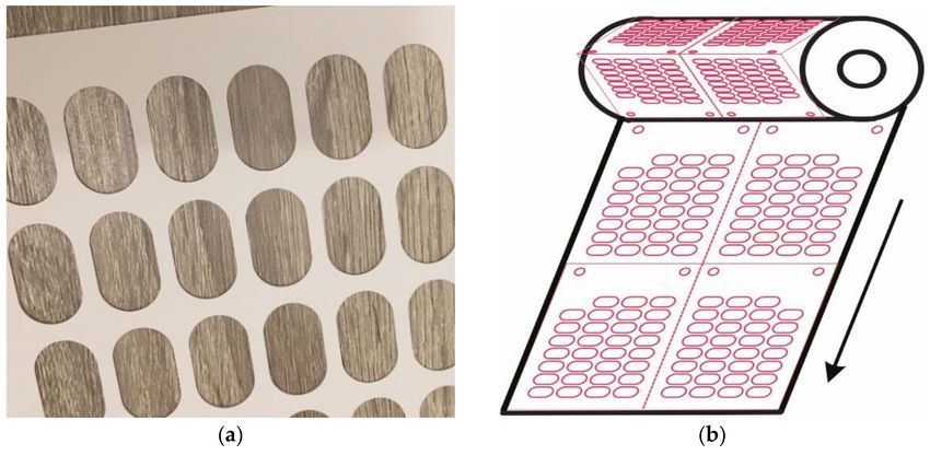
Metals 2021, 11, 996                                                                                                                    2 of 22

                                     repetitive at a high rate of production. The commonly used cutting dies are the flexible
                                     ones. This type has the advantage of low price and versatility [6].
                                          The technical characteristics of flexible die refer to the following elements: metal sheet
                                     thickness, cutting blade angle, die cut nest shape, number of repetitions of die cut nests,
                                     die cut length (for calculating the product framing per die cut), and cutting/perforating
                                     blades height (Table 1).

                                             Table 1. Technical characteristics of flexible dies.

                 Characteristics                                                         Description
                                                    The die cut assembly is influenced by the size of the clearance between the active
              Metal sheet thickness
                                                                   part of the magnetic cylinder and against the anvil;
                                                   It depends on the material of the product that will be cut with the help of the die cut
               Cutting blade angle
                                                                      (paper, foils, cardboard, special materials);
                                                   The die cut nest is the finished product cut by shape: rectangle, circle, ellipse, special
                Die cut nest shape
                                                     shape, and particular shapes with transverse/longitudinal blade/perforation;
             Number of repetitions                        Number of nests per die cut, in transverse and longitudinal direction;
                                                   The longitudinal dimension of the die cut or the perimeter of the magnetic cylinder
                                                                              is calculated with the formula:
                Die cut repetition                                            Repetition (mm) = Z × p (mm)
                                                   where Z is the number of the gear teeth of the magnetic cylinder in question, and p is
                                                                  the gear pitch that is taken from the machine booklet;
                                                        The calculus is made according to the thickness of the print medium to be
      Cutting/perforating blades height
                                                                         cut/perforated and the type of die cut.

                                          Our research in this paper is focused on cold-work steel flexible dies.
                                          Tool steels used to cut or form materials’ environmental temperature are called cold-
                                     work tool steels. A cold-work steel die cut has a long working life, lower wear over time,
                                     and good hardness [7].
                                          Cold-work tool steels can operate at temperatures up to 200 ◦ C and are characterized
                                     by good wear resistance over time. These properties depend on the application field and
                                     process parameters’ set-up.
                                          Tools from this type of material can be used for dies, bending, and forming rolls,
                                     cutting tools for machining centers, taps, drilling, piercing, etc. Other applications are in
                                     mold industry, tube forming, metal cutting, and machining, etc.
                                          Due to large use in industry, the cold-work tool steel manufacturers continuously
                                     improve the material composition and treatments for specific customer requirements.
                                          This group of metallic materials has the largest use in the tool manufacture field due
                                     to good price-quality ratio and good behavior in heat treatment [8].
                                          In cycle processes, intensive contact and friction between the tool and work material
                                     can damage the active surfaces, which creates a poor-quality product over time, as well as
                                     gaps in the process workflow (due to repairing and replacing over time).
                                          To increase the cutting die working life strong stainless steel is recommended [9].
                                          The main objective of the paper was the analysis of how the values of the moment of
                                     die cut tightening force correlated with the die cutting speed both influence the wear of the
                                     knives on the die cut.
                                          The research aimed to optimize the variation of technological parameters correspond-
                                     ing to several flexographic flexible die.
                                          This considered parameters such as the height of die cut teeth, wear, speed of die
                                     cutting, moment of tightening force, and length of die cut material.
Metals 2021, 11, 996 3 of 22
2. Materials and Methods
2.1. Materials
A flexible die cut quality is defined by cutting edge geometry and material character-
istics. The die steel must be shock resistant and at the same time have high durability [10].
Additionally, it must allow for multiple cycle of mounting and unmounting of the die on
the magnetic cylinder. The workflow type and process parameters influence the choice of a
specific material for manufacturing the die cut.
The flexible die used in the experimental research were made of 50CrMo4 according to
EN 10083-3-2006, and the 50CrMo4 steel alloy had the chemical composition from Table 2.
Table 2. Chemical composition of 50CrMo4 steel (1.7228): EN 10083-3-2006.
C Si Mn P S Cr Mo
0.46–0.54 max 0.4 0.5–0.8 max 0.025 max 0.035 0.9–1.2 0.15–0.3
The 50CrMo4 steel for tools has a very good resistance to abrasion, stability, and
thermal conductivity. It is calibrated and has stability at high temperatures.
The die cutting is made for an abrasive material, specifically a thin cardboard used for
making foldable boxes, called “cardboard” [10], with a weight of 280 g/m2 and thickness
of 450 µm. The cardboard has a layered composition, with both sides coated but with
different degrees of roughness according to Table 3. The image of cardboard with a layered
composition is shown in Figure 1a.
Table 3. The cardboard has a layered composition.
Feature, Unit of Measurement Standard Tolerance Value
Thickness µm ISO 534 +/−3% 50
Weight g/m2 ISO 536 +/−2% 80
Moisture content % ISO 287 +/−1.0% 8.5
Roughness of the face of material µm ISO 8791-4 max 1.3 0.8
Roughness of the back of material µm ISO 8791-4 max 6 4
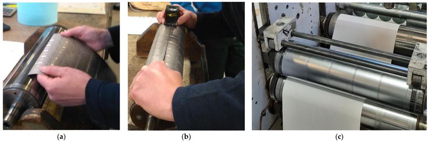
Figure 1. The final product: (a) sample of the cardboard with a layered composition and (b) design
of a finished roll.
The product is delivered in a roll with an outer diameter between 800 and 900 mm and
a width of 310 mm. The roll with the finished product is obtained directly from the printing
machine, going through the following manufacturing processes: printing, die cutting,
lateral cutting at the ordered width [11,12] and on the winding direction requested by the
customer without having to be moved for finishing on the longitudinal cutting machines.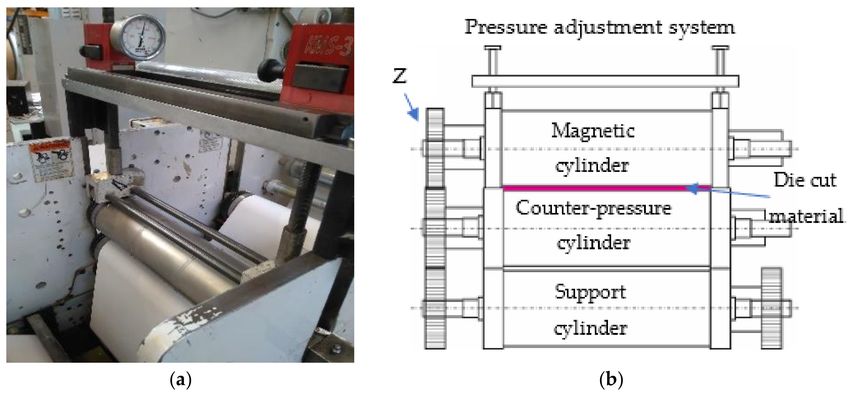
Metals 2021, 11, 996                                                                                             4 of 22

                            The finished product is then cut from the roll, piece by piece, having a flat, rectangular
                       shape that folds in the middle after perforation [13]. Holes are arranged symmetrically
                       and are placed on both halves, so that after folding they overlap perfectly (Figure 1a,b).
                       The shape of the holes corresponds to a rectangle with two opposite sides in the shape of a
                       semicircle, measuring 27 mm × 11 mm.
                            The finished roll (Figure 1b) has a total of 62 such holes on the product that is to be
                       die cut, 31 for each half. The folded product also has a φ = 11 mm diameter hole in two
                       corners and close to the edges, for a total of 4 holes per product. The printing direction of
                       the product is longitudinal, along the folding perforations. The dimensions of the die cut
                       products were 310 mm × 228.6 mm, where:
                       •    Th width of the product is 310 mm, represented by the dimension measured trans-
                            versely, perpendicular to the printing direction;
                       •    The perforator is positioned in the middle of the width and divides the two halves
                            into 155 mm each;
                       •    The length of the product is 228.6 mm, represented by the dimension measured
                            longitudinally, in the printing direction.

                       2.2. Die Cutting Technology
                             Flexographic printing machines can have one or two die cut assemblies [14]. De-
                       pending on the type of machine, these dies cut assemblies can be an integral part of the
                       construction of the printing line, or they can be independent, mobile structures, which can
                       be mounted in the machine line when die cutting is required and detached when un-died
                       products are printed, for example, foils.
                             In both types of machines, the die cut assemblies are positioned at the exit end of the
                       material from the printer, following the printing assemblies. Immediately after die cutting
                       the product is pulled on a roller shaft in the roller, when the product is delivered in rolls, or
                       is taken on a conveyor when the product is delivered in pieces [5]. The construction of a
                       die cut assembly essentially involves two cylinders engaged vertically, of which at least
                       one is magnetic, on which the flexible die cut is mounted, and the other cylinder plays the
                       role of providing counter pressure.
                             The arrangement of the cylinders in the assembly in the up or down position, corre-
                       lated with the type of each cylinder, magnetic or counter pressure, favors the obtaining of
                       certain types of products; thus [6]:
                       •    The magnetic cylinder mounted on top engages with a counter-pressure cylinder, self-
                            adhesive or non-self-adhesive labels are die cut, and thin cardboard is perforated/cut
                            out/cut into sheets;
                       •    A counter-pressure cylinder mounted on top engages with the magnetic cylinder, and self-
                            adhesive labels are stamped on the back with longitudinal or transverse perforations/cuts
                            with functional role (faster removal of the label from the silicone support).
                            When the machines have two die cut assemblies (fixed in the machine or removable)
                       more complex products can be obtained by successive die cutting of the material, such as
                       the following:
                       •    In the first die cut assembly, the magnetic cylinder with die cut is mounted at the
                            bottom, and in the second die cut assembly, the magnetic cylinder with die cut is
                            mounted at the top; both magnetic cylinders run with counter-pressure cylinders;
                            the dies used are paired, and self-adhesive products or thin cardboard labels with a
                            functional role are obtained;
                       •    When the construction allows it, this last process can be extended by mounting two
                            magnetic cylinders in a single die cut assembly, one up and the other down; thin cardboard
                            products with ribs are obtained (bending lines for the finished, preformed product).
                            In either variant, an engraved cylinder could be used instead of the magnetic cylinder
                       and the die [13].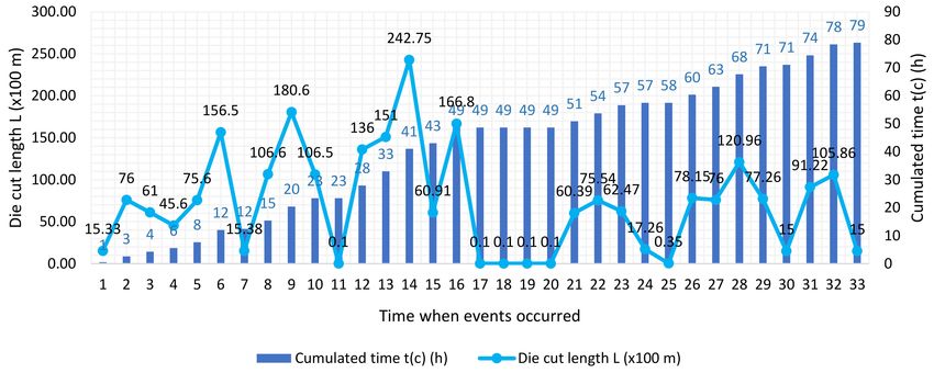
Metals 2021, 11, 996                                                                                                               5 of 22

                                       From the constructive point of view of the printing machine, the die cut assembly, as
                                  shown in Figure 2, is the last station through which the printing medium passes before
                                  re-rolling on the shaft as a semi-finished or finished product.

                                  Figure 2. Flexographic die cut assembly: (a) die cut assembly picture and (b) schematic representation
                                  of the die cut assembly.

                                      The construction of a flexographic die cut assembly generally involves the following el-
                                  ements: die cut pressure adjustment system/device, and flexible die mounted (Figure 3) on
                                  a magnetic cylinder tangent to a counter-pressure cylinder running on a support cylinder.

      Figure 3. Mounting die cut: (a) positioning the die cut on the marking line of the cylinder, (b) checking the alignment of the
      edges of the die cut with a 10× printing magnifying glass, and (c) cylinder with die cut mounted in the die assembly.

                                        The number of rotations of the magnetic cylinder depends on the number of teeth
                                  of the gear and is equal to the number of rotations of the printing cylinder. The printing
                                  medium is die cut in the passage between the two cylinders, the resulting waste being
                                  lifted on an upper shaft and rolled.

                                  2.3. Presentation of the Shape of the Teeth and Their Characterization from the Point of View of the
                                  Obtaining Technology
                                       Generally, the flexible dies have specific recommendations for the cutting angle,
                                  corresponding to the manufacturer. From the production data and the experience of the
                                  manufacturers [5,6], the cutting angle depends on the type of printing medium to be die
                                  cut (Figure 4). The cutting of the paper media is done by a strong pressing of the fiber by
                                  means of the blade, so that the material is practically broken by thinning in the contact area.
                                  In the case of foils, the edge of the cutting blade must be sharp to pierce the material.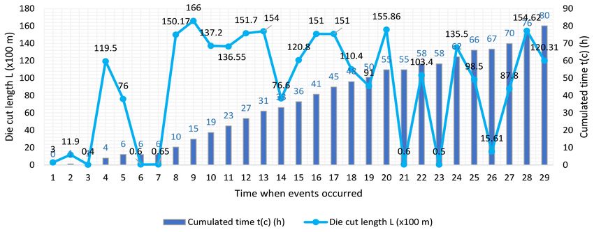
Metals 2021, 11, 996                                                                                                   6 of 22

                       Figure 4. Schematic representation of the correlation of the printing media with the angle of the
                       cutting blade.

                            The product is cut to the finished width by die cutting with a flexible die cut mounted
                       on the magnetic cylinder in the die cut assembly, which is mounted in line with the printing
                       machine. After passing through the die cut assembly, the product is cut, perforated, and
                       cut laterally to the finished width. In this context, it will be possible to apply the formula
                       for establishing the number of measurement intervals [15].
                            By die cutting, the cardboard is perforated by the knives on the die (Figure 5). The
                       piercing is initiated by the tension of the material strip in the machine (30 daN) and is
                       completed by the extreme pressing of the cardboard fibers followed by their breaking. This
                       operation is programmed on the control panel of the machine depending on the processed
                       material and its thickness [16].

                       Figure 5. Die cut knives: (a) die cutting process and (b) geometry of the die cut knives. H—the height
                       of the knives; h—the thickness of the die cut sheet; α—the cutting angle for cardboard or paper.

                            The geometry of the knife (Figure 5b) is the result of machining on numerically
                       controlled machines and is characterized by the following parameters: α = 60◦ ÷ 75◦ —the
                       cutting angle for cardboard or paper; H (mm)—the height of the knives; h (mm)—the
                       thickness of the die cut sheet.

                       2.4. Parameters Used to Adjust the Flexible Die
                            The following parameters are defined in the die cut assembly involving the magnetic
                       cylinder on which the die cut, and the counter-pressure cylinder are mounted:
                       •    Gap—the space between the body of the magnetic cylinder and the counter-pressure
                            cylinder (Figure 6a), which is calculated as follows:

                                              Gap = (Φ Bearer ring − Φ Magnetic cylinder)/2                               (1)
                            For the magnetic cylinder used to die cut the finished product studied, the value of
                       the gap is:
                                            Gap = 145.586 mm − 143.806 mm = 0.890 mm                         (2)
                       •    Clearance—the empty space between the tip of the knife and the counter-pressure
                            cylinder; in the case of metal-on-metal die cutting it has a positive or zero value, and
                            in the case of self-adhesives it has a negative value (cut the face of the material to the
                            liner) (Figure 6b).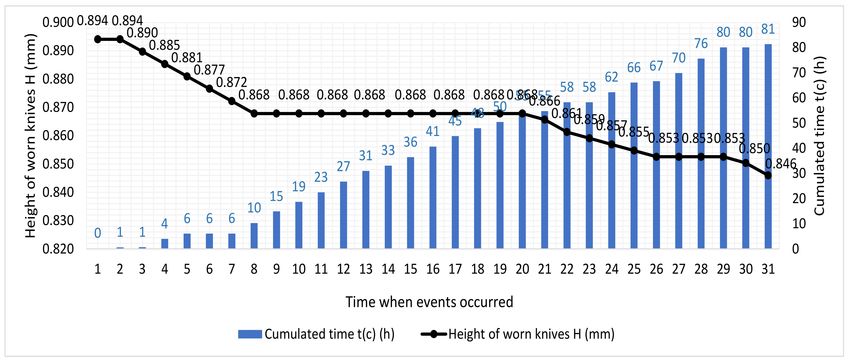
Metals 2021, 11, 996                                                                                                                   7 of 22

                                   Figure 6. Parameters of the die cut assembly: (a) gap definition and (b) clearance definition.

                                         With this data, the height of the knives on the die cut is calculated as follows:

                                                                            H = Gap + Clearance                                            (3)

                                        Depending on the print run of the die cut product and the printing medium, the die
                                   cut can be chrome plated with the possibility of laser hardening of the tip of the knives
                                   (Figure 7a). The height of the knife can be obtained by a final finishing by milling the
                                   faces of the knife (Figure 7b) or by grinding the back of the die in the areas where there
                                   are knives on the face of the die (Figure 7c). These fineness operations are performed on
                                   numerically controlled machines [16].

      Figure 7. (a) Improving the quality of the die cut; (b) finishing by milling of the face of the knife; (c) grinding of the back of
      the die cut under the knife.

                                   2.5. Parameters Used in the Construction of the Analyzed Representative Flexible Die
                                         The parameters used in the construction of the analyzed representative flexible dies
                                   are presented in the Table 4. The experimental studies were performed on 3 types of flexible
                                   dies (M1, M2, M3) for processing the same product.
                                         The flexible dies are designed so that for each complete die cutting obtained by a rotation
                                   of the magnetic cylinder on which the die cut is mounted, 2 pieces of product with the following
                                   characteristics result: 8 circular holes, Φ = 11 mm, 124 rectangular holes with two semicircular
                                   sides measuring 27 mm × 11 mm, and die cut repetition = 2 × 228.6 mm = 457.2 mm.
                                         All 3 flexible dies, M1, M2, and M3, had the same dimensions of the flat contour of
                                   500 mm × 457.2 mm and were made with the same knife geometry, height, and angle at
                                   the top, each with the same total number of lengths of knives per die that were processed.
                                         At the non-chrome-plated M1 die cut and the chrome-plated M2 die cut, the height
                                   of the knives was obtained by a last fine passage with a milling cutter on the knife faces.
                                   At the chrome-plated M3 die cut, after the laser hardening of the knife tip, the height was
                                   obtained by fine grinding of the die on the back, only in the areas with a knife on the front
                                   of the die [17,18].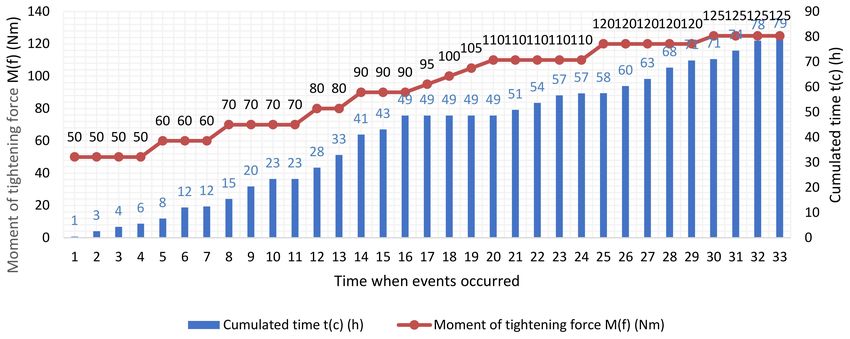
Metals 2021, 11, 996                                                                                                             8 of 22

                                 Table 4. Flexible die—technical parameters for adjustment of the die cutting.

                                                      Parameters                           Notation            UM           Value
                                                               Geometrical parameters of die cut knife
                                  Knife height (nominal value)                                 H               mm           0.893
                                  Cutting angle                                                α                ◦            60
                                                                   Production technical parameters
                                  Moment of tightening force with torque spanner             M(f )             Nm          40 ÷ 125
                                  Arm length of the spanner                                   d                 m            0.460
                                  Material tensioning                                         T                daN             30
                                  Material clearance in the machine                           j                mm           0.5 ÷ 1
                                  Normal printing speed                                       v               m/min         50 ÷ 60

                                      In the die cutting assembly all 3 dies, M1, M2, and M3, were mounted on the magnetic
                                 cylinder positioned above, in engagement with the counter-pressure cylinder positioned
                                 below, and the die cutting was done by actuating from top to bottom.
                                      By chrome plating the die cut, an increase in hardness and wear resistance is obtained,
                                 as well as an increase in refractoriness. From this perspective, the flexible dies are divided
                                 into the following generic quality steps: standard, basic, and basic plus (Table 5).

                                                  Table 5. Classification of die cuts.

       Quality                       Treatment                                            Recommendations
                                                                    -    Print runs of hundreds of meters;
                                   No treatment                     -    It is not possible to die cut metal-on-metal (the product
      Standard
                                   (50CrMo4-1)                           must not be cut-out, perforated, cut by piercing the material
                                                                         on the entire thickness);

                                                                    -    Print runs of thousands of meters;
        Basic                     Chrome plating
                                                                    -    For metal-on-metal die cutting;

                                                                    -    Print runs of hundreds of thousands of meters;
                       Chrome plating + laser hardening at the      -    For die cutting of paper/cardboard;
     Basic Plus
                                 tip of the knives                  -    For abrasive materials: thermal paper, substrate printed
                                                                         with white ink.

                                      The chrome-plating process consists of a technique of galvanizing a thin layer of
                                 chromium on the steel plate. The chrome layer hardness and resistance to corrosion
                                 and wear increases the surface behavior to hard working conditions. An average of
                                 0.03–0.3 mm thickness chrome layer must be uniformly deposed over the steel base. For
                                 extreme conditions of working, the layer thickness can be increased up to 15 µm or more.
                                 For punches, dies, and molds, the hardness specification starts from 50 HRC [19–21].
                                      The chromium layer is electrolytically deposited, as it has a controlled thickness. Thus,
                                 the deposited chromium layer in this study had a thickness of 15 µm. In the case of the
                                 chrome die, the tolerance of the knife height was +/−0.0025 mm, and the final height was
                                 obtained by a last grinding operation. In the case of the chrome-plated and laser-hardened
                                 punch, the tolerance of the knife height was +0.0025/−0.005 mm and the final height was
                                 obtained by a last grinding operation.
                                      A separation of ions from the chemical bath by using a flow current is needed to
                                 depose a chrome layer on the part surfaces. The process parameters, like flow current and
                                 process time, depends on the part size. Usually 30–40 Amps per 0.01 m2 applied for 1 h
                                 generates a deposition rate between 25 and 30 µm.
                                      The properties of hard chrome-plating processes are reported in [22].
                                      High hardness is usually 63–70 HRC—considered to be hard chrome. It is ideal for
                                 use in molds and dies area, for bearing and sliding parts [23].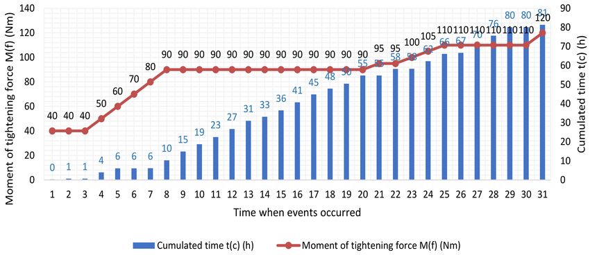
Metals 2021, 11, 996                                                                                            9 of 22

                            Wear layer is when the chrome layer is used and can be removed by chemical methods,
                       only in the defective area, and re-plated without damaging the base part. The re-plated
                       process can be repeated until the base part is damaged. By replacing only the wear layer
                       instead of all parts, the cost of maintenance decreases in the field of molds and dies working
                       in abrasive environments [24].
                            The third die cut studied, M3, was first chrome plated and then laser hardened.
                            Laser hardening is a simple way to improve and increase the hardness of a metal part.
                       This has the effect of increasing the lifetime of the component [25]. The laser processes are
                       state of the art in industrial applications due to flexibility and accuracy. Laser can be used
                       for heat treatment, cutting, vaporizing, melting, and welding metal parts together with
                       other applications for different types of materials.
                            The laser-hardening process is known as surface layer hardening. The laser beam
                       can heat up the part surface up to hardening temperature. The process is very precise for
                       application where some small areas need to be heated in a short time. The temperature
                       is rapidly increased to more than 1000 ◦ C at a high rate to austenitize a surface layer [26].
                       The cooling of the part can be done by different methods like conduction, convection, or
                       radiation modes. No supplementary cooling is needed [26].
                            Other advantages of laser hardening [27] include a lower risk of warping and cracking,
                       and at the same time, an increase of the fatigue strength. Compared with the traditional heat
                       treatment method, the main advantage consists of high accuracy control of the temperature
                       and high speed of the process with low distortion and hardness stress [28–31].
                            A high degree of wear occurs when we die cut by piercing the material to its full
                       thickness, because the cutting edges of the knives on the die directly hit the counter-pressure
                       cylinder, which is why laser hardening of the tip of the knives is recommended.

                       2.6. Tooth Wear Measurement Technology
                            The following parameters were measured for the experimental study:
                       •    Variation of the height of die cut teeth;
                       •    Die cutting length measured in linear meters of die cut material with each type of M1,
                            M2, and M3 die cut.
                           For the calculation n, the number of measurement intervals, the experimentally deter-
                       mined relation of Sturges was applied [15]:
                                                            n = 1 + 3.322 lg(N)                                    (4)
                       where lg(N) is the logarithm in base 10 of the total number of N measurements; the result
                       obtained was rounded to the nearest whole number.
                            To determine K, the size of intervals based on H.A. Sturges, the following relation
                       was applied:
                                                         K = (Hmax − Hmin )/n                                (5)
                       where Hmax and Hmin represent the maximum and minimum values in the series of mea-
                       surements for each die cut, respectively. For each measurement interval the arithmetic
                       mean was calculated and with it the arithmetic mean value of the height of the worn knives
                       was obtained.
                            The intervals I (Imin, Imax) are calculated as follows:
                            The minimum value for each interval Imin is the maximum from the previous one,
                       and the maximum is calculated by adding the size of intervals K.
                                            Imini = Imaxi−1 ; Imaxi = Imini + K, where i = 1 to n                  (6)
                             The application of the arithmetic mean shows a lack of consistency in the case of
                       dispersed measurements, so that if the extremes have a low frequency compared to the
                       rest of the measurements, they may distort the value of the calculated average. Because of
                       this, the extreme intervals that had a frequency between 1 and 3 were eliminated from the
                       series of measurements, a number accepted for the series of 80 measurements. The values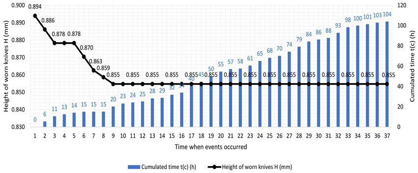
Metals 2021, 11, 996                                                                                            10 of 22

                       of the new intervals, which became limits of the series of measurements, determined the
                       maximum and minimum values of the height of the worn knives.
                            The wear of the knives on the die cut is directly proportional (as noted by experimental
                       tests) to the increase in the moment of tightening force, so:
                       •    It is necessary to bring the die close to the anvil to penetrate by cutting the entire
                            thickness of the material, and tightening shall be done with the machine running;
                       •    By changing the printing speed, the thickness of the material can be penetrated by cutting.
                            These two considerations were considered when determining the number of degrees
                       of knife height wear over the entire period of use of each die cut analyzed.
                            The highest wear degree of the knife height was the variation from the maximum height
                       of the new knife, noted as H new max., to the minimum height of the worn knife, noted as H
                       worn min., with these values being allowed for the graphical analysis of knife wear.
                            All values in the experiment were calculated to 8 decimal places and the final figures
                       were rounded as follows:
                       •    The height of the knives to 3 decimals, to be in accordance with the order of size of the
                            gap and the clearance given in 3 decimals;
                       •    Time in integers to facilitate the image of evolution over time.

                       2.7. Experiments Scheduling
                            The experiments were scheduled by applying the method of factorial experiments.
                       Thus, for the tightening of the dies, small values of the die tightening were respectively
                       chosen, such as M(f ) = 50; 70 Nm, as well as usual values of the tightening of the die,
                       M(f ) = 90; 110 Nm, and for the die cutting speed, accepted values were chosen for printing
                       in the printing process of the products from this range, namely v = 50; 60 m/min.
                            The flexible die M1 (non-chrome-plated die) and M2 (chrome-plated die), as well as the
                       M3 chrome-plated and laser-hardened die were tested, and two variable parameters with
                       four and two levels, respectively, were established, performing 24 experiments according
                       to Table 6.

                       Table 6. Programming of M1, M2, and M3 experiments by the method of factorial experiments.

                              Number of              The Moment of Tightening Force M(f ) (Nm)     Speed v (m/min)
                             Experiments             50           70          90          110      50          60
                                M1_1                  X                                             X
                                M1_2                              X                                 X
                                M1_3                                           X                    X
                                M1_4                                                       X        X
                                M1_5                  X                                                        X
                                M1_6                              X                                            X
                                M1_7                                           X                               X
                                M1_8                                                       X                   X
                                M2_1                  X                                             X
                                M2_2                              X                                 X
                                M2_3                                           X                    X
                                M2_4                                                       X        X
                                M2_5                  X                                                        X
                                M2_6                              X                                            X
                                M2_7                                           X                               X
                                M2_8                                                       X                   X
                                M3_1                  X                                             X
                                M3_2                              X                                 X
                                M3_3                                           X                    X
                                M3_4                                                       X        X
                                M3_5                  X                                                        X
                                M3_6                              X                                            X
                                M3_7                                           X                               X
                                M3_8                                                       X                   X

                           The time analysis of the use of flexible die indicated the calendar working days in print
                       production, divided at intervals corresponding to the rotation of printing workers, which
Metals 2021, 11, 996 11 of 22
were 8 h, respectively. During these, the events at which variations of the die cut’s moment
of tightening force were required, or changes of the die cutting speed were necessary, were
recorded, both determining the wear of the knives measured by the length of the die cut
material, which was measured in linear meters. Marking these events allowed for the
graphical analysis of the experiments.
To reflect the succession of the steps of operation of the die cut, the time consumed for
each die cut length at the corresponding speed was calculated:
t = L/v (7)
where: t = time (minutes), L = die cut length measured in linear meters (m), v = die cut
speed (m/minute), and the values transformed in full hours were cumulated to mark the
evolution over time of the analyzed variables.
For all 3 types of flexible die analyzed—M1, M2, and M3—the periods in which they
worked in identical operating conditions were taken into account, respectively, until the
appearance of the first waste that was not completely ejected from the nests, in which
case the worn knives could no longer ensure total penetration of the material thickness.
In the graphical analysis we used the chronograms, and we represented the wear times.
Regarding the construction of graphs: on the Ox axis, the time at which the events occurred
was mentioned, the Oy axis corresponds to the values of the variable of interest, and on the
secondary axis Oy, the cumulative number of operating hours of the die cut, corresponding
to the moments marked by events, was noted.
The analyzed flexible die—M1, M2, and M3—were equipped with 2 longitudinal
knives for cutting the width of the material; they had the same number of knives per die,
thus the same number of wastes at each rotation of the cylinder, which were, respectively,
128 pieces being ejected.
3. Results and Discussion
3.1. Results Obtained in the Case of Teeth without Chrome Plating (Die Cut M1)
In order to assess the behavior in operation of the three types of dies, the wear of
the knives was analyzed by measuring the height H of the knives and the length of the
die cut material. The results from Table 7 reflect the molds durability obtained in the
experimental research.
During the entire period of operation of the M1 die cut, a number of 31 moments were
registered, in which the moment of tightening force of the die cut or the die cutting speed
was modified. The knives registered a continuous and relatively constant wear with short
intervals of small quantities of die cut material at constant tightening and speed.
Thus, the largest amount of die cut material was made at the value of 90 Nm of the
moment of tightening force (Figure 8) and the speed of 50 m/min (Figure 9), cumulating
in a die cut length of 47,046 m (Figure 10). Due to the wear of the knives, their height
decreased to 0.875 mm (Figure 11). These values were recorded starting with time 14
when the die cut had 41 h of operation and until time 16 when the die cut reached 49 h of
operation. Basically, the die worked 16 h at the most with the moment of tightening force
and speed remaining constant. After 239,253 m of die cutting over 79 h of operation, the
first non-ejected waste appeared. Until now, the die cut worked in technical conditions
identical to the M2 and M3 flexible die.Metals 2021, 11, 996 12 of 22
Table 7. Experimental results on the durability of molds.
Knives’ Height Length of Die Cut Material
Number of Experience
H (mm) L (×100 m)
M1_1 0.894 15.33
M1_2 0 0
M1_3 0.875 470.46
M1_4 0.867 0.10
M1_5 0.894 182.60
M1_6 0.886 393.70
M1_7 0 0
M1_8 0 0
M2_1 0 0
M2_2 0 0
M2_3 0 0
M2_4 0.855 98.50
M2_5 0.885 119.50
M2_6 0.877 0.60
M2_7 0.868 1752.28
M2_8 0 0
M3_1 0.894 0.35
M3_2 0.787 257.70
M3_3 0.863 0.50
M3_4 0 0
M3_5 0 0
M3_6 0 0
M3_7 0 0
M3_8 0 0
Figure 8. Variation of the moment of tightening force of the M1 die cut during the operating period.
Figure 9. Variation of die cutting speed during the period of operation of the M1 die cut.Metals 2021, 11, 996 13 of 22
Figure 10. The length of the die cut material with each change in the moment of tightening force or speed for the M1 die cut.
Figure 11. The wear of M1 die cut knives depends on the variation of the knife height at each event.
In order to increase the life cycle of the M1 die, waste disposal was improved as follows:
• In the first stage, the waste trapped by the nests was removed with a lamella stop
before winding on the finished roll;
• Subsequently, it was necessary to install additional blowers to remove all waste.
These steps were considered when determining the decrease for the wear degree from
the maximum height of the new knives to the minimum height of the worn knives when
they were withdrawn from use at 0.846 mm.
At the appearance of the first waste that was not completely ejected from the nests,
the M1 non-chrome-plated die had a height of 0.852 mm of the worn knives (Figure 11).
Keeping them in production after this moment, with the supplementation of waste ejection
methods, led to an increase in the wear of the knives, their height decreasing to 0.846 mm,
a value measured when withdrawing the die cut.
The same value of 0.846 mm was measured when withdrawing the M2 chrome-plated
die cut, with the difference being that here, only then did the first non-ejected waste from
the nest appear.
These identical values obtained at the physical withdrawal of the two flexible die from
production, namely the M1 non-chrome-plated die (value resulting in extreme conditions)
and M2 chrome-plated die (value obtained under experimental conditions), emphasize that
the rolling of the flexible die takes place in the same empty space between the shoulders of
the running cylinders, between the magnetic cylinder on which the die cut is mounted and
the counter-pressure cylinder (Figure 6).Metals 2021, 11, 996 14 of 22
As long as the same thickness, type and quality of material is die cut (thin cardboard),
this space allows is to increase the moment of tightening force until the knives wear to
the threshold of 0.846 mm, after which the flexible die can no longer be used, and they
are withdrawn.
The durability of a die is related to the amount of die cut substrate until the time
of complete wearing of at least one knife per die. Complete wear means the inability of
the knife to completely cut/cut-out/perforate the entire thickness of the substrate due
to blunting.
Dd = LT /R [rotations] (8)
where Dd is the die cut durability, LT is the total length of die cut material (meters), R is the
repetition of the magnetic cylinder (m/rot).
R = Z · p [inch] = Z · 25.4 · p [mm] (9)
where Z it is number of teeth on the gear of the magnetic cylinder and p is the gear pitch
(Figure 2b).
The repetition of magnetic cylinder used is as follows:
R = (72 · 25.4 · 1/4)[mm]/1000 = 0.4572 [m/rotation] (10)
The durability of M1 non-chrome-plated die cut is:
Dd M1 = 239, 253 [m]/0.4572 [m/rotation] = 523, 300 [rotations] (11)
3.2. Results Obtained in the Case of Teeth with Chrome Plating (Die Cut M2)
The M2 die cut had the same geometry of the teeth as the M1 die cut but differed from
it in the sense that the active part was chrome plated.
During the entire period of operation of the M2 die cut, a number of 31 important
times were registered; thus:
• Time 6 is one of the transition times to a moment of the upper tightening force and is
characterized by a small length of die cut material at 60 m (Figure 12); this is because,
following the increase of the moment of tightening force at 70 Nm (Figure 13), the
cutting of the material was incomplete, causing the appearance of non-ejected waste
from the nests and causing a new increase of the moment of tightening force at the
next value, while keeping constant a speed of 60 m/min (Figure 14). At time 6, the M2
die cut had 6 h of operation and the height of the knives had decreased to 0.877 mm
(Figure 15);
• The highest amount of die cut material was obtained starting with time 8 when the die
cut had 10 h of operation, and up to time 20, including when the die cut had 55 h of
operation; during this period, the chrome-plated M2 die cut worked 49 h, cumulating
in a die cut length of 175,228 m (Figure 12), with constant values of the moment of
tightening force of 90 Nm (Figure 13), a speed of 60 m/min (Figure 14), and a knife
height of 0.868 mm (Figure 15). This constant over time of the height of the knives
indicated an increase in the durability of the die cut.Metals 2021, 11, 996 15 of 22
Figure 12. The length of the die cut material with each change in the moment of tightening force or speed for the M2 die cut.
Figure 13. Variation of the moment of tightening force of the M2 die cut during the operating period.
Figure 14. Variation of die cutting speed during the operating period of the M2 die cut.Metals 2021, 11, 996 16 of 22
Figure 15. The wear of the M2 die cut knives depending on the variation of the height of the knives at each event.
The M2 die cut was withdrawn when the first non-completely ejected waste from the
nests was removed, or when the worn knives no longer ensured the total penetration of
the material thickness, with the maximum moment of the tightening force being 120 Nm.
Durability of the M2 die cut = 271,157 m/0.4572 m/rotation = 593,081 rotations (12)
3.3. Results Obtained in the Case of Die Cut M3
The M3 die cut had the same structure as the M1 and M2 die cuts, respectively, except
that its teeth were subjected to hard chrome plating and a laser-hardening process.
Throughout the analyzed operating period, the M3 die cut recorded a number of
37 times. Starting with time 9, the only element that changed its value over time was the
length of the die cut material, the variable parameters such as the moment of tightening
force and the die cut speed remained constant, and the wear of the knives did not vary.
Thus, the largest amount of die cut material was made with a moment of tightening
force of 100 Nm (Figure 16) and a speed of 50 m/min (Figure 17), cumulating in a total of
266,597 m of die cut material (Figure 18). A die knife with a height of 0.855 mm (Figure 19)
was used. These values were recorded starting with time 9 when the die cut reached
20 operating hours, and up to time 37, when the die cut reached 104 operating hours.
Basically, the die cut worked for a maximum of 89 h with the moment of tightening force
and speed staying constant, and the die cut remaining in production.
Durability of the M3 die cut = 312,120 m/0.4572 m/rotation = 682,677 rotations (13)
Figure 16. Variation of the moment of tightening force of the M3 die cut during the operating period.Metals 2021, 11, 996 17 of 22
Figure 17. Variation of die cutting speed during the operating period of the M3 die cut.
Figure 18. The length of the die cut material with each change in the moment of tightening force or speed for the M3 die cut.
Figure 19. The wear of the M3 die cut knives depending on the variation of the height of the knives at each event.Metals 2021, 11, 996 18 of 22
3.4. Discussion
The heights of the knives on the flexible die were measured before the first printing
and after their withdrawal from production. In total, 80 measurements were performed,
and to establish the maximum and minimum values, the arithmetic mean values were
calculated on consistency intervals of the measurements.
The macrostructure analysis was performed with the help of a metallographic optical
microscope Basic VIS microscope produced by KERN. Analysis under a 50× microscope
of the two adjacent knives on the worn M1 non-chromed die (Figure 20) indicated the
existence of two different profiles, characterized as follows: one was strongly rounded and
the other flattened, which highlights their uneven wear in the context that both knives
simultaneously enter in the die cutting of the abrasive material, which was a thin cardboard.
The images were taken at the physical withdrawal of the die cut from production, when
the minimum height of used knives measured 0.846 mm.
Figure 20. M1 die cut: (a) wear of the knife on the left side and (b) wear of the knife on the right side.
The wear of the chrome-plated M2 die cut knives was highlighted with a 50× micro-
scope. Figure 21 shows how the tip area is strongly flattened in case of two knives, which,
being joined, simultaneously enter the die, so the shape of the worn tips is similar. The
images were taken when the M2 die cut was withdrawn from production, when the first
waste was not completely ejected, and with a minimum height of used knives of 0.846 mm.
After a maximum die cut length of 312,120 m was obtained with the chrome-plated
and laser-hardened M3 die cut knives, a low degree of wear was found on the tip of the
knives seen under a 50× microscope, which appeared slightly blunt compared to the other
flexible die (Figure 22).Metals 2021, 11, 996 19 of 22
Figure 21. M2 die cut: (a) wear of the knife on the left side (b) wear of the knife on the right side.
Figure 22. M3 die cut: (a) wear of the knife on the left side (b) wear of the knife on the right side.
The analysis of the experiments results of non-chromed M1, chrome-plated M2, and
laser chrome-plated M3 flexible dies by the method of factorial experiments (Table 6)
highlighted the following:
• On both intervals of the moment of tightening force related to the speed of 60 m/min
and the speed of 50 m/min; a higher wear of the chrome-plated M2 knives was found
compared to the non-chromed M1, the difference being 9 µm at the first set of valuesMetals 2021, 11, 996 20 of 22
of the moment of tightening force/speed, and gradually increased to 12 µm at the
last set of values of the moment of tightening force/speed. The total length of die cut
material in the first interval with small values of the moment of die cut tightening
force M(f ) = 50; 70 Nm, and the speed of 60 m/min, was higher at the M1 non-chrome-
plated die, at 82,378 m, compared to 19,550 m at the die cut with the chrome-plated
M2 die, in the same interval. This interval is not usually used for printing because it is
a transition interval;
• The M3 chrome-plated and laser-hardened die cut, for the working interval at a
constant speed of 50 m/min with a M(f ) of 90 Nm clamping moment, had a higher
wear than the M1 and M2 dies. The wear difference between M3 and M1 was about
14 µm and between M3 and M2 it was about 3 µm. A higher productivity was
achieved for the M3 die. The total length of cut material without any error was
266,697 m (Figures 16–18, times 7–37);
• The length of die cut material at the usual values of the moment of the tightening force
M(f ) = 95 to 110 Nm, and at a speed of 50 m/min, was higher at the chrome-plated M2
punch, at 33,790 m (Figures 12–14, times 22–25), compared to the non-chrome-plated
M1 die cut, which, at each moment of the tightening force, had a minimum length
of material of 10 m (Figures 8–10, times 17–20), a fact indicating successive moments
of transition of the moment of tightening force from 95 Nm to 100 Nm, and then to
105 Nm and 110 Nm, after which the moment of tightening force was kept constant,
but the speed decreased to 45 m/min. This is the optimal interval for the moment of
tightening force;
• The identification of the highest heights of the knives at the non-chrome-plated M1
die cut, at the same time as the existence of frequent changes of moments of tightening
force or die cutting speed, resulted from the fact that at least one sufficiently worn
knife appeared on the active surface of the non-chrome-plated die, as not to completely
penetrate the material, and the resulting waste remaining attached to the nest. The
random wear of the knives is owed to the variation in thickness of the die cut cardboard
and to the fact that the paper/cardboard are highly abrasive materials that affect the
integrity of the die cut knives;
• For the three die cuts, the appearance of waste attached to the nest resulted in the
immediate application of an additional moment of tightening force or a change in die
cutting speed; these moments were marked by small quantities of die cut material at
moments of tightening force and constant speed;
• The waste caught in the windings of the finished roll means scrap, which can be
corrected only by a double rerolling of the material on another machine: at the first
run the waste caught in the winding falls, and at the next reroll the correct direction of
the graphics on the roll is given;
• The immediate intervention of the printing worker in adjusting the moment of tight-
ening force or speed is necessary, otherwise, the much-accentuated wear of at least
one knife leads to waste caught in the nest by the greater thickness of material texture,
which allows for ejection only by pulling it manually; thus, the finished product roll is
compromised, and it cannot be recovered.
4. Conclusions
The experimental analysis of the M1 non-chromed, M2 chrome-plated, and M3 chrome-
plated and laser-hardened dies (Table 6) highlighted the following:
• The M1 non-chromed die had the highest values of the height of the knives, of
0.873 mm and 0.871 mm, but had a minimum amount of die cut material, of 10 m each,
thus indicating that both are in transition to higher values of the moment of tightening
force of the die, from 95 Nm to 100 Nm, and from 100 Nm to 105 Nm, respectively
(Figures 8 and 9, times 17 and 18); the transition values are indicators that on the
surface of the die there is at least one point on a knife edge that is below the calculatedMetals 2021, 11, 996 21 of 22
height, which does not allow for the complete penetration of the material in the point,
and un-ejected waste from the nest remains;
• The M2 chrome-plated and M3 chrome-plated and laser-hardened dies both recorded
a knife height of 0.859 mm with a quantity of 50 stamped meters; this indicates a
transition moment at a higher value as follows: at the M3 die cut, the moment of the
tightening force increased from 95 Nm to 100 Nm (Figures 16 and 17, times 8 and
9), and at the M2 die cut, the moment of the tightening force increased from 100 Nm
to 105 Nm (Figures 12 and 13, times 23 and 24); both flexible die showed a greater
wear in at least one point on the edge of a knife, which did not allow for the complete
cutting of the material in that point, with the waste remaining trapped in the nest;
• The M3 chrome-plated and laser-hardened die had the lowest knife height, of 0.855 mm,
with the longest length of material that was die cut at 266,600 m (Figures 12 and 13,
times 9–37); this die cut length indicates the uniformity of the height of the knives
over the entire surface of the die, namely, the uniform wear of all knives at any point
on the edges, as well as the ability of the die to completely penetrate the material in
all cutting areas. The extrapolation analysis of the data on the durability of the flexible
die through Equations (11)–(13) highlighted the following:
• The durability of the M3 die cut was higher than that of the other two, because it
had chromed and laser-hardened knives, and the fact that it remained in operation in
production for a longer time indicates a further increase in durability over the value
of 682,677 rotations, with a constant wear of all knives on the surface of the die and at
any point on the edges;
• The durability of the chrome-plated M2 die cut was higher than that of the non-chrome-
plated M1 die by 69,781.27 rotations, which means that it die stamped ~31,900 m more
than the non-chromed die; thus, the chrome plating of the M2 die cut improved
the resistance of the knives to cutting cardboard, which is an abrasive material; the
durability of the non-chromed M1 die cut compared to that of the chrome-plated
M2 die cut indicates the low die cutting strength of an abrasive material (cardboard),
which had thickness variations of +/−3% (Figure 1), from 0.4635 mm to 0.4365 mm,
resulting from the manufacture.
It was demonstrated that by chrome plating and laser hardening the knives, an
increase of the maximum stamped length was obtained, together with a uniform wear
of the knives and a decrease of the number of adjustment times. In the future, we will
determine how the variation of the thickness and roughness of the abrasive, stamped
material (thin cardboard) can influence the type of wear of the knives.
Author Contributions: Conceptualization, G.V.N., C.M., D.F.A., and D.D.; methodology, validation,
G.V.N., C.M., and D.F.A.; formal analysis, G.V.N. and D.D.; investigation, G.V.N., C.M., and D.F.A.,
resources, G.V.N.; data curation, G.V.N., C.M., and D.F.A.; writing—original draft preparation. All
authors have read and agreed to the published version of the manuscript.
Funding: This research received no external funding.
Data Availability Statement: Not applicable.
Conflicts of Interest: The authors declare no conflict of interest.
References
1. Kipphan, H. Hanbook of Print Media Technologies and Production Methods; Springer: Berlin/Heidelberg, Germany, 2001; Volume 1,
pp. 773–901. ISBN 978-3-540-29900-4. [CrossRef]
2. Kamp, F. Die-cutting—An important part of the process. Flexo Tech 2005, 74, 63.
3. Geilen, M.B.; Schoenherr, J.A.; Klein, M.; Leininger, D.S.; Giertler, A.; Krupp, U.; Oechsner, M. On the Influence of Control Type
and Strain Rate on the Lifetime of 50CrMo4. Metals 2020, 10, 1458. [CrossRef]
4. Rotary die-cutting around the world. Int. Pap. Board Ind. 2005, 48, 34–38.
5. Wink Stanzwerkzeuge GmbH & Co. KG, Supercut Flexible Dies for Labels, Cutting Angle & Material. Available online:
https://www.wink.de/products/flexible-dies/wwwwinkdesupercut/ (accessed on 5 May 2021).Metals 2021, 11, 996 22 of 22
6. Spilker GmbH. Flexible Dies. Innovative Run of Flexible Dies for Each Requirement. Available online: https://www.spilker.com/
en/products/flexible-dies.html (accessed on 5 May 2021).
7. Vieweg, A.; Ressel, G.; Ressel, G.; Prevedel, P.; Marsoner, S.; Ebner, R. Effects of the Inductive Hardening Process on the Martensitic
Structure of a 50CrMo4 Steel. HTM J. Heat Treat. Mater. 2017, 72, 3–9. [CrossRef]
8. Blaz, S.; Burja, J.; Medved, J. Modification of non-metallic inclusions with rare earth metals in 50CrMoV13-1 steel. MTAEC9 2019,
53, 441–447. [CrossRef]
9. Maharjan, N.; Murugan, V.K.; Zhou, W.; Seita, M. Corrosion behavior of laser hardened 50CrMo4 (AISI 4150) steel: A depth-wise
analysis. Appl. Surf. Sci. 2019, 494, 941–951. [CrossRef]
10. Telasang, G.; Majumdar, J.D.; Padmanabham, G.; Manna, I. Wear and corrosion behavior of laser surface engineered AISI H13 hot
working tool steel. Surf. Coat. Technol. 2015, 261, 69–78. [CrossRef]
11. HELIOS Elio Cavagna Srl. Top-Knives. Available online: https://www.heliosslitting.com/en/type_shear_cutting_blades.php
(accessed on 5 May 2021).
12. The World Material. DIN EN 1.2842 Steel 90MnCrV8 Material Equivalent, Datasheet, Properties, Composition. Available online:
https://www.theworldmaterial.com/din-en-1-2842-steel-90mncrv8-material (accessed on 14 March 2021).
13. Folea, G.V.; Cazac, V. The Analysis of the Particularities of Flexible Dies and of the Options to Ensure Quality in Flexo Die Cutting.
Ann. Acad. Rom. Sci. Ser. Eng. Sci. 2018, 10, 29–42.
14. Kocher+Beck GmbH + Co. Totationsstanztechnik KG, Tooling Technology IOC Flexible Dies. Available online: https:
//www.kocher-beck.com/en/productsdivisions/tooling-technology/deinline-offset-cutting-ioceninline-offset-cutting-ioc/
ioc-flexible-dies/ (accessed on 2 February 2021).
15. Sturges, H.A. The choice of a class interval. J. Am. Stat. Assoc. 1926, 21, 65–66. [CrossRef]
16. Steneholm, K.; Andersson, N.A.I.; Tilliander, A.; Jönsson, P.G. The role of process control on the steel cleanliness. Ironmak.
Steelmak. 2018, 45, 114–124. [CrossRef]
17. Fakir, R.; Barka, N.; Brousseau, J.; Caron-Guillemette, G. Analysis of the Mechanical Behavior of AISI 4340 Steel Cylindrical
Specimens Heat Treated with Fiber Laser. J. Manuf. Process. 2020, 55, 41–56. [CrossRef]
18. Barka, N.; El Ouafi, A. Effects of Laser Hardening Process Parameters on Case Depth of 4340 Steel Cylindrical Specimen—A
Statistical Analysis. J. Surf. Eng. Mater. Adv. Technol. 2015, 5, 124–135. [CrossRef]
19. Bielewski, M. Replacing Cadmium and Chromium. In RTO-AG-AVT-140; NATO Research and Technology Organization:
Neuilly-sur-Seine, France, 2011; Chapter 23; pp. 1–22.
20. Benaben, P. An Overview of Hard Chromium Plating Using Trivalent Chromium Solutions. Available online: https://www.
pfonline.com/articles/an-overview-of-hard-chromium-plating-using-trivalent-chromium-solutions (accessed on 25 April 2021).
21. Hardchrome Engineering Pty Ltd. Hardchrome Plating. Available online: http://www.hardchrome.com.au/wp-content/
uploads/2017/11/HCOnePageFlyerrev2.pdf (accessed on 25 April 2021).
22. Fukaura, K.; Yokoyama, Y.; Yokoi, D.; Tsujii, N.; Ono, K. Fatigue of cold-work tool steels: Effect of heat treatment and carbide
morphology on fatigue crack formation, life, and fracture surface observations. Metall. Mater. Trans. A 2004, 35, 1289–1300.
[CrossRef]
23. Saha, S.K.; Prasad, L.; Kumar, V. Experimental investigations on heat treatment of cold work tool steels: Part 1, Air-hardening
grade (D2). Int. J. Eng. Res. Appl. 2012, 2, 510–519.
24. Patwa, R.; Shin, Y.C. Predictive Modeling of Laser Hardening of AISI5150H Steels. Int. J. Mach. Tools Manuf. 2007, 47, 307–320.
[CrossRef]
25. Titanova, Inc. What is Laser Hardening. Available online: https://www.titanovalaser.com/blog/what-is-laser-hardening/
(accessed on 25 April 2021).
26. Dinesh Babu, P.; Balasubramanian, K.R.; Buvanashekaran, G. Laser surface hardening: A review. Int. J. Surf. Sci. Eng. 2011, 5,
131–151. [CrossRef]
27. Fakir, R.; Barka, N.; Brousseau, J. Case study of laser hardening process applied to 4340 steel cylindrical specimens using
simulation and experimental validation. Case Stud. Therm. Eng. 2018, 11, 15–25. [CrossRef]
28. Laser Surface Engineering, Laser Hardening. Available online: https://www.nutech.de/en/services/laser-centre/surface-
engineering/laser-hardening.html (accessed on 5 May 2021).
29. Xiong, W.Y.; Liu, J.Q.; Luo, W.Y. Several new technologies to replace hard chromium plating. J. Electroplat. Finish. 2006, 25, 50–53.
30. ELUVIO, s.r.o. ELUVIO Flexible Dies. Available online: http://www.vyseky.cz/en/products/cutting-tools (accessed on 5 May 2021).
31. SINKOTECH Micro Industrial Technologies Inc. Flexible Dies. Available online: https://www.sinkotech.com/eng/kesim-
kaliplari.html (accessed on 5 May 2021).You can also read