Designing and Planning a Campus Wireless Local Area Network - Mengdi Ji Bachelor's Thesis Information Technology May 2017 - Theseus
←
→
Page content transcription
If your browser does not render page correctly, please read the page content below
Mengdi Ji
Designing and Planning a Campus
  Wireless Local Area Network
           Bachelor’s Thesis
        Information Technology

              May 2017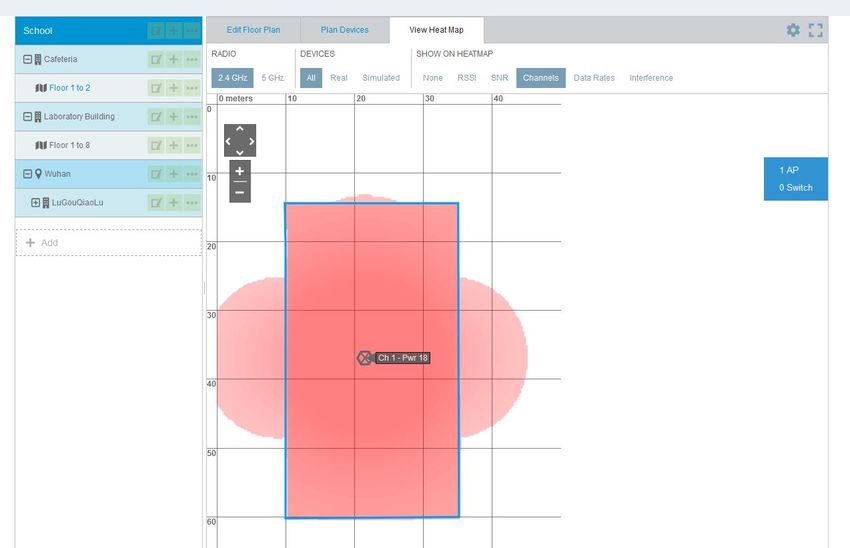
Author (authors)                       Degree                        Time

Mengdi Ji                              Bachelor of Engineering       May 2017

Title

Designing and Planning a Campus Wireless Local Area Network

Commissioned by

Supervisor

Reijo Vuohelainen
Abstract

With the speedy social and economic development networks have been progressing rap-
idly. But the current local area network couldn’t meet users’ demands to certain extent es-
pecially on campus. The aim of the study was to get full knowledge of WLANs and the
basic processes of designing a campus WLAN.

This paper introduced the theoretical part of WLANs, including advantages and limitations
of WLANs, protocol standards of WLANs, components of WLANs, different topologies of
WLANs and also the security of WLANs. The contents also included the basic process of
planning a campus WLAN, designing a topology by using VISIO and planning APs by using
HiveManager NG and Floorplanner tools, and also list hardware and the budgets with the
selected components.

In the end, the thesis is good for studying the basic idea about WLAN design but not
enough for the real environment. With the complexity of the wireless network, IT groups
should spend more time and consider more aspects about the WLAN design process.

Keywords

WLAN, campus network, technical standards, security
CONTENTS

1     INTRODUCTION .............................................................................................. 1
2     THEORY OF WIRELESS LOCAL AREA NETWORKS .............................. 2
  2.1      Definition of Wireless Local Area Networks ........................................ 2
  2.2      Advantages of Wireless Local Area Networks .................................... 3
  2.3      Limitation of Wireless Local Area Networks ........................................ 3
  2.4      Wireless LAN Transmission Media....................................................... 4
  2.5      Technical Standards of Wireless Local Area Network ....................... 4
      2.5.1 802.11 Series ........................................................................................... 4
      2.5.2 Bluetooth ................................................................................................ 7
      2.5.3 HomeRF................................................................................................... 8
  2.6      Wireless Network Components ............................................................ 8
  2.7      Channel .................................................................................................... 9
  2.8      Wireless Local Area Network Topologies .......................................... 11
  2.9      WLAN Security ...................................................................................... 12
      2.9.1 Open Authentication ............................................................................. 12
      2.9.2 Shared Key Authentication.................................................................... 13
      2.9.4 EAP Authentication ............................................................................... 14
      2.9.4 WEP....................................................................................................... 15
      2.9.5 WPA/WPA2............................................................................................ 16
3     PRACTICAL PART ......................................................................................... 16
  3.1      Background of the School ................................................................... 17
  3.2      Request Analysis .................................................................................. 17
  3.3      WLAN Topology..................................................................................... 19
  3.4      Channel Management .......................................................................... 20
  3.5      AP Management ................................................................................... 22
  3.6      Security of the WLAN ........................................................................... 28
  3.7      Lists of Hardware and Budgets ........................................................... 30
4     CONCLUSION ................................................................................................ 36
REFERENCE ............................................................................................................ 38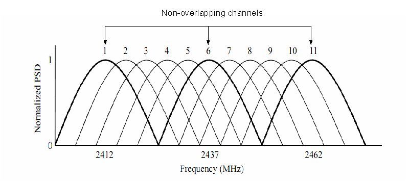
1

1   INTRODUCTION

Along with the constant development of social economy, computer networks
have changed people’s lifestyle in many aspects. Local area network, which is
widely applied, plays a more and more important role in medical treatment, mil-
itary, education and science. Not only enterprises and companies build LANs,
but also families and schools establish their own small LANs.

With LANs, work and study efficiency is improved, but it also brings some prob-
lems. Wired local area networks couldn’t work without the cable, which
means that we couldn’t change the structure of networks casually according to
actual situations. Therefore, we cannot implement mobile office and stud-
ies. Therefore, the current local area network couldn’t meet users’ demands to
certain extent. In order to make users access data at any place and at any time,
networks should develop from being wired and fixed to being wireless and mo-
bile.

Compared with local area networks, wireless local area networks offer ad-
vantages at different places. One of the advantage of a wireless local area net-
work is that if there is coverage of WLAN, users can move anywhere they want
with their devices and transmit data at the same time. Other advantages in-
clude easy installation, effective expansion, flexibility and cost savings.

In terms of campuses, most campuses now have their own wired local area net-
work, but teachers and students need a more convenient way to access the
network. According to my survey in WUHAN, over 90 percent of the high
schools didn’t have their WLAN right now but only some of the international
schools have the WLAN. With WLAN, teachers and students can use the same
device to get connected to the network at anytime and anywhere. Therefore, in
that case, WLAN is the most efficient way to extend the wired local area network,
especially on campus.

In this project, I will design a WLAN for my high school. I will introduce basic
knowledge of wireless LAN, designing and planning a wireless local area net-
work based on the actual situation of my high school. And, I will also introduce
2

the topology, AP management, channel management and which way I decided
to use for the security part. Most of my planning bases on the hardware part of
campus the wireless LAN.

The aim of the study is to get knowledge of the definition, background, charac-
teristics and technical standards of WLAN, to understand the advantages and
limitations of WLAN and to get to know the basic process of designing a cam-
pus WLAN. I will introduce the theory of wireless local area networks in the first
part of the paper and describe the basic process of designing a campus WLAN
in the second part of the paper. Then, I have a conclusion for the thesis.

2     THEORY OF WIRELESS LOCAL AREA NETWORKS

This chapter will define what WLAN is. The advantages and limitations of WLAN
and the technical standards and components of WLAN are introduced. This
chapter will also define different topologies, channel and authentication methods
in WLAN.

2.1   Definition of Wireless Local Area Networks

There are many different kinds of computer networks in the world, as shown in
Figure 1, including global area network (GAN), wide area network (WAN), met-
ropolitan area network (MAN) and local area network (LAN). Among them, wire-
less local area network is one type of LAN.

Figure 1. Different networks (Animasigaia 2014)
3

Wireless local area networks use infrared or radio waves to provide network for
wireless devices and allow users to transmit data between each other in the
coverage area without the limitation of wire and cable. WLANs have different
wireless network protocols, such as IEEE802.11, Bluetooth, HomeRF and
HiperLAN. Many wireless devices support WLAN, including mobile phones,
game consoles, some cameras, tablets and also GPS systems. WLANs may
contain two devices or up to one hundred and more. (Bradley 2016.)

2.2   Advantages of Wireless Local Area Networks

Wireless local area networks have unique advantages in many places. Firstly,
wireless local area networks are more flexible and mobile than the wired ones
and they will not be limited by cables. Users may have access to or receive
information at any network coverages in real time. Secondly, WLANs have good
scalability. Users can add more APs to effectively expand the network so as to
meet the needs of specific applications and installations. Thirdly, WLANs no
longer require a lot of wires and cables, which will reduce the workload of net-
work cabling. Finally, it is easier to set up a WLAN than a wired one and it cannot
be easily affected by the natural environment or disasters.

2.3   Limitation of Wireless Local Area Networks

There are also limitations of WLANs. Firstly, WLANs are based on radio fre-
quency for data transmission. Walls or buildings will block the transmission of
radio frequency, reduce the signal and then influence the performance of
WLANs. Secondly, some of the devices have the same frequency as 802.11
series and it may cause radio signal interference. Thirdly, wireless LANs are
less secure than wired LANs. When LANs travel through the air, it might be
intercepted at the same time. Some unauthorized devices may use user’s
WLAN at the same time. Fourthly, the coverage areas of WLAN is limited,
WLANs have a certain range of coverage, increasing the coverage area needed
to increase the wireless hot spots at the same time, therefore the cost will in-
crease at the same time. What’s more, if some wireless devices hack into the
user’s network, their bandwidth will be stolen at the same time. (Bradley 2016.)
4

2.4   Wireless LAN Transmission Media

There are three main transmission media for WLANs. The first one is microwave
and the range of frequencies is 1GHz to 40GHz. Microwave is not a true sense
of the LAN technology, it is used to interconnect the buildings’ local area network.
It is suitable for point-to-point transmission and also satellite communications.
The second media is radio and the range of frequencies is 3KHz to 300GHz.
This transmission media is currently widely used, because the radio wave has
wide coverage. It is suitable for all the applications. The difference between
broadcast radio and microwave is that the radio didn’t require antennas. And,
the radio’s former is omnidirectional and the microwave’s former is directional.
The third one is infrared. The infrared uses transmitter and receiver to modulate
non-coherent infrared light. The difference between infrared and microwave
transmission is that infrared will not penetrate walls. And, there is no frequency
allocation problem for the infrared, because it doesn’t required license. (Vittorio
2008.)

2.5   Technical Standards of Wireless Local Area Network

Users have many choices when they are looking for network gear. Many prod-
ucts conform to the 802.11 series wireless standards, also known as Wi-Fi tech-
nologies. There are also various other wireless technologies, such as Bluetooth,
HomeRF and HiperLAN. They are designed for specific networking applications.

2.5.1 802.11 Series

According to Microsoft, the IEEE 802 standards define two separate layers for
the Data-Link layer of the OSI model. The one is Logical Link Control Layer and
the other is media access control Layer. As shown in Figure 2, the IEEE 802.11
wireless standard defines the specification of the physical layer and the media
access control layer that communicate up to the LLC layer. The components of
the 802.11 architecture will fall into physical layer or media access control layer.
5

Figure 2. OSI model and 802.11 (Microsoft 2003)

The first standard of the 802.11 series appeared in 1997 and it was created by
the institute of Electrical and Electronics Engineers. The 802.11 only supports
2Mbps bandwidth and it can’t meet the demands of the users anymore.

The 802.11b version was introduced in 1999. It supports 11Mbps bandwidth and
it uses direct sequence spread spectrum technology. The 802.21b uses 2.4GHz
frequency and some of the devices will interference 802.11b, if they work at the
same frequency, like microwave. The effective range for indoor place is about
100 meters, for outdoor place about 300 meters. The cost of 802.11b is lower
than the later version 802.11a and the signal range is better than the 802.11a,
but the speed is slower than the 802.11a. The 802.11b uses Direct Sequence
Spread Spectrum for modulation.

The 802.11a version was created at the same time as 802.11b. It uses orthog-
onal frequency division multiplexing for data modulation. It supports voice, data
and image transmission. It also supports 54 Mbps bandwidth and is suitable for
big business market while 802.11b is suitable for users’ home market at that
time. 802.11a uses Orthogonal Frequency-Division Multiplexing technology for
modulation. OFDM is a coding technique that splits the radio signal into several
sub signals before they reach a receiver. Using OFDM will reduce the interfer-
ence between signals. The 802.11a has higher speed and frequency than
6

802.11b, but 802.11a has short range signal and it’s easily obstructed. (National
Instruments 2015.)

The 802.11g version appeared in 2002. It supports 54 Mbps bandwidth and 2.4
GHz frequency. It was created to come up with the interoperability between
802.11a and 802.11b. 802.11g uses OFDM technology. According to Bradley,
the 802.11 g was designed for cross compatibility, the devices can join the net-
works, even the APs running at a different 802.11 version.

The 802.11n version was the development of 802.11g. The rate was increased
to 600Mbps. And, it supports 2.4GHz and 5GHz frequency. 802.11n can im-
prove the quality of wireless transmission. It combines MIMO and OFDM tech-
nologies. MIMO means multiple in multiple out and it is commonly used in home
routers for coordinated use of the multiple radio antennas in wireless network.
The MIMO technology can increase the bandwidth and the range of the network.
(Bradley 2017.)

The 802.11ac version is popular one in the market. It appeared in 2012. It is a
faster and scalable version than 802.11n. 802.11ac supports 1Gbps data rate
and 5GHz frequency. The comparison between different 802.11 WLAN technol-
ogies is in Table 1.

Table 1. 802.11 Wireless Standards

 IEEE         802.11b     802.11a      802.11g         802.11n      802.11ac
 Standard
 Release      1999        1999         2003            2009         2012
 Year
 Frequency 2.4GHz         5GHz         2.4GHz          2.4or5GHz 5GHz

 Data Rate    11Mbps      54Mbps       54Mbps          600Mbps      1Gbps

 Modula-      DSSS        OFDM         DSSS,OFDM OFDM               OFDM
 tion

It's clearly that the data rate has become faster with time going by. The 802.11
series use different frequency and modulation to meet different situations.
7

2.5.2 Bluetooth

Bluetooth is a wireless communication protocol created in 1994 by Ericsson
company and used for connecting devices through the air. It is slower than WIFI,
but it is easy to set up and usually used for data transfer between devices. It
can help devices transmit data between each other within 10 meters. It works
at the frequency of 2.4GHz and the data rate is about 1Mb/s. Bluetooth is most
commonly used between mobile phones for photos or files transfer. According
to Samraiz(2014), there are number of Bluetooth versions which all are being
developed to meet the particular requirements of the time. All the updated ver-
sions of Bluetooth offer backward version compatible. This means whichever
newer version you are using then it is compatible with the older version as well.
Users may also transfer data through WLAN. But there are differences between
WLAN and Bluetooth. The Bluetooth works in lower distance range than in
WLANs. The WLANs are also faster than Bluetooth. But sometimes Bluetooth
is a better option when users need to transfer data between mobile phones.
Table 2 shows about the comparison between 802.11b and Bluetooth.

Table 2. Comparison between 802.11b and Bluetooth

                        Wireless LAN                    Bluetooth
                        Wireless LAN stands for
                        Wireless Local Area Net-        Bluetooth is a short range
                        work. It refers to a network    technology standard
Definition              that connects two or more       which allows devices to
                        devices by using wireless       communicate in a wireless
                        data connections over short     manner.
                        distances.
Distance Range          Up to 200 feet                  Less than 30 feet
Bandwidth               High                            Low
Security issues         Can occur, still controllable   Minimum
Speed                   Comparatively more              Comparatively less
Central Access Point Required                           Not required
                                                        By checking out the Blue-
Identification of the   By locating a central router of
                                                        tooth control panel (on
network                 a wireless network switch.
                                                        phone or computer)
8 Even Bluetooth is a short range technology and the bandwidth is lower than WLAN but it’s still an important wireless technology for users to transfer data between devices. 2.5.3 HomeRF HomeRF was designed for home users to enable wireless communication be- tween computers and other wireless devices in 1998 by the Home Radio Fre- quency Working Group. It works at the frequency band of 2.4GHz and the data rate is about 1Mb/s. The communication range for HomeRF is about 50 meters and the main purpose is to establish an interoperable network for families. There are something in common between HomeRF and Bluetooth technologies. Both of them operate at the frequency band of 2.4GHz and all of them are de- signed for short-range, low-power applications. There are also difference be- tween these two technologies. HomeRF was designed for home networking en- vironments but Bluetooth technology is optimized for mobile phones. The com- munication range of HomeRF is about 50 meters and for Bluetooth is about 10 meters. Both of these two technologies have similar rate at about 1Mbps but HomeRF version 2.0 has data rate up to 10Mbps, so HomeRF require more power than Bluetooth. (Brent 2011.) 2.6 Wireless Network Components The main components of WLANs including client devices, access point, wire- less network adapters, wireless routers, wireless controller and wireless anten- nas. Client devices are also known as stations. All the end devices with wireless capabilities will act as client devices, for example, mobile phones, laptops and PDA. The network interface cards, also known as wireless adapters, act as the inter- faces of WLAN, and they are required for the devices when they want to access the WLANs. There are three different types of network interface cards, including PCMCIA, PCI and USB. The PCMCIA cards are designed for the laptops and supports hot swapping, it means that users can replace or add the network in- terface cards without shut down the devices. The PCI cards are suitable for
9

desktop computers while the USB sticks are suitable for both desktop comput-
ers and laptops.

The wireless router can function as a normal router or a access point. Most of
the wireless routers are designed for home users. The wireless routers have
firewall inside in order to protect home users from being hacked. Even if wire-
less routers differ in many different ways, normally just one router is required
for an entire family.

The access point acts as a bridge between wireless devices and wired networks.
APs are commonly used in large buildings in order to create a wireless local
area network that expands to a wide range of area. Home users can add an AP
but not router if they want to expand their network, while office users can add
more than one APs to expand the network to the whole building.

The wireless controllers used to automatically manage and configure a set of
APs. The features of the wireless controllers including load balancing, coverage
hole detection and correction and interference detection and avoidance. (Wik-
ipedia 2017) What’s more, there are also antennas in WLANs. The function of
antennas is to transmit and receive electromagnetic waves, users can expand
the coverage of wireless LAN by using antennas. The transmission rate is sig-
nificantly reduced when wireless devices are far from the AP or other devices,
and antennas will come in handy to enhance the signal and speed up the trans-
mit rate at the same time.

2.7   Channel

The interference is an issue which will influence users’ WLANs performance.
The three main causes of the interferences are: Co-Channel, Adjacent-Channel
and Non-Wi-Fi, as shown in Figure 2. And, the channel related interferences
can be reduced or eliminated by selecting the proper channels for the networks.
( Metageek no date.)
10

Figure 3. The three main causes of WiFi interference (Metageek no date)

The IEEE divides 14 channels for 2.4GHz band. As shown in Figure 8, the dis-
tance between each channel is 5MHz and they may overlap frequency, because
each of the channel is 22MHz wide and the entire spectrum is 100 MHz (Aldxn-
dra 2015). Only channels 1,6 and 11 will not overlap each other.

Figure 4. 2.4GHz band channel ( Stefan & Vladimir 2012)

Selecting the right channels will reduce the interference and increase the net-
work performance.
11

2.8   Wireless Local Area Network Topologies

There are three different kinds of WLAN topologies, including IBSS, BSS and
ESS. The IBSS refers to Independent Service Sets, also known as ad-hoc net-
work. As shown in Figure 2, users can directly transmit data between each other
without access points. At least two wireless stations are needed for each topol-
ogy. We can easily build a small WLAN in an office by using IBSS topology. But
all the nodes have to use the same channel.

Figure 5. Independent basic service sets

The BSS refers to Basic Service Set, also known as Infrastructure BSS. It re-
quires an access point when users want to communicate with each other, as
shown in Figure 3.

Figure 6. Basic service set

The ESS refers to Extended Service Set. It can be regarded as combining mul-
tiple BSSs together with a distribution system on the same network, as shown
12

in Figure 4. ESS often has two or more APs and it can cover a wider area than
BSS.

Figure 7. Extended service set

IBSSs are suitable for huge enterprises because they need many devices and
all the devices need high speed transmission. BSSs are suitable for home users
because the devices don’t need high speed data transmission.

2.9    WLAN Security

Security has always been an important part of wired or wireless network. As
time goes by, threats for all privacy information transferred from client devices
through WLAN are growing. It’s time to protect WLAN from being attacked. At
very beginning, WLANs use Service Set Identifier for their security. Clients use
SSID to join WLAN. Some WLANs will enter the media access control in access
point to control access devices. Both of these two methods are not good solu-
tions for security anymore.

2.9.1 Open Authentication

There are different ways for WLAN authentication. The open authentication
method is the the default and easiest way for authentication in 802.11 standards.
This method allows any workstations access the AP. Users send an authentication
request to the access point to get an authentication response from the access point.
13

After that process users can access the AP successfully. This method can be eas-
ily used for unauthorized access. But if the device wants to pass data, its Wired
Equivalent Privacy keys must match the access point's Wired Equivalent Pri-
vacy keys. As shown in Figure 5, the device's WEP key does not match the access
point's key, it means that the device can authenticate but can not transfer data.
(Cisco 2009.)

Figure 8. Open Authentication      Cisco 2009

Now, most of the enterprises and schools will not use the open authentication for
security any more.

2.9.2 Shared Key Authentication

The shared key authentication, as shown in Figure 6, The users send an authenti-
cation request to the AP and when the AP received request it will send a challenge
text back to the user, then the user encrypts the text and sends the text to the AP.
And, the AP will authenticate the user after AP decrypt the text successfully and
match the text to the original one. The user can access to the AP after these pro-
cess.

Figure 9. Shared key authentication (Cisco 2009)
14

The shard key authentication will cause problem. Because both the unen-
crypted challenge text and the encrypted challenge can be monitored, it means
that the hacker can calculates the WEP key by comparing the unencrypted and
encrypted text to attack the APs, so the shared key authentication can be less
secure than open authentication. (Cisco 2009.)

2.9.4 EAP Authentication

The EAP authentication will provide the highest level of security for the wireless
network. The wireless device and the RADIUS server will mutual authentication
by using EAP authentication. The process of EAP authentication are shown in
Figure 9.

The EAP authentication will provide the highest level of security for the wireless
network. The wireless device and the RADIUS server will mutual authentication

by usi
ng EAP authentication

Figure 10. EAP authentication (Cisco 2009)

The client devices will send a authentication to the access point, then the ac-
cess point will identity the request, after the client send the username and the
AP relay it to the RADIUS server, the RADIUS server will send an authentication
challenge back to the client. The client will use a one-way encryption of the
15

password to give a response to the challenge then send the response to the
RADIUS server. The RADIUS server will create it’s own response and compare
with the client’s response. When the RADIUS server authenticates the client,
the authentication is completed. The client and the RADIUS server will create a
unique WEP key for the client to access the appropriate level of network. Then
the client will use the key for logon session. During the logon session, the
RADIUS server will encrypt the WEP/session key then send it to the access
point. The access point will encrypt its broadcast key and also the session key
then send the encrypted broadcast key to the client, the client will use the ses-
sion key to decrypt it. The client and AP will use the session and broadcast WEP
keys for all communications. Even there are many different types of EAP au-
thentication, but the access point has the same behaves. The AP will relay au-
thentication messages from the wireless client to the RADIUS server and also
from the RADIUS server to the wireless client. (Cisco 2009.)

2.9.4 WEP

WEP refers to Wired Equivalent Privacy and it was introduced in 1999. It’s a
security protocol in order to protect the wireless network from being attacked.
As shown in Figure 7, WEP utilizes RC4 encryption algorithm to encrypt data.
WEP supported encryption keys of 40 bits and 24 additional bits of system-
generated data, the length of the key is 64 bits. Later WEP extended to support
longer keys including 104-bit, 128-bit and 232-bit variations. WEP is unsafety
and useless because it’s easy for hacker to determine the WEP key in several
minutes by using simple tools. (Bradley 2017.)

Figure 11. WEP encryption (RF Wireless World 2012)
16

2.9.5 WPA/WPA2

WEP is the weakest method for the security of the WLAN compare to WPA and
WPA2, so it was replaced by WPA in 2003. The are different kinds of WPA and
WPA2 mode types, as shown in Table 2.

Table 3. Comparison of WPA and WPA2 Mode Types

                                     WPA                         WPA2

 Enterprise Mode (Business,   • Authentication: IEEE   • Authentication: IEEE
                              802.1X/EAP               802.1X/EAP
 Government, Education)
                              • Encryption: TKIP/MIC   • Encryption: AES-CCMP

 Personal Mode (SOHO,         • Authentication: PSK    • Authentication: PSK
 Home/Personal)
                              • Encryption: TKIP/MIC   • Encryption: AES-CCMP

WPA stands for Wi-Fi Protected Access. WPA is also known as the draft IEEE
802.11i standard. It provides stronger encryption than WEP by using temporal
key integrity protocol and advanced encryption standard technologies. WPA de-
signed for home user is called WPA-PSK. It’s the most simplified and powerful
form of WPA. A person who uses WPA-PSK will configure a static key for secu-
rity. And, WPA uses the Temporal Key Integrity Protocol to generate the en-
cryption key. WPA2 is another version of WPA to security the network and
WPA2-PSK a simple and safety choice for most of the home users. But WPA2
will decrease the performance of the network because encryption and decryp-
tion process are needed. (Bardley 2017.)

3   PRACTICAL PART

In the practical part, the main purpose is to introduce the basic process of the
campus WLAN design. I will introduce the background of the school, the request
analysis of the school, the topology of the WLAN, the channels and APs man-
agement of the WLAN, the security of the WLAN and the hardware of the WLAN.
17 3.1 Background of the School The campus is a special place for the students to learn something new and campus network has become an important platform to gain deeper knowledge. Due to this, the construction of the network in the campus environment has become an important necessity. The number of students who uses their own device is increasing rapidly, this increase the stress on the network. Only using the devices available on the campus is not enough and it cannot meet the re- quirement of the students. Many universities have switched to wireless network, which is easy to access and cost efficient. The advantages of the wireless net- work cannot be matched by the wired network. In this project, I will design a WLAN for my high school. The actual situations of the campus should be considered before designing the WLAN. This school has one main building, one student dormitory, one complex building, one gym and one laboratory building. About 2,000 students are studying and 250 teachers are working there. 3.2 Request Analysis In this project, the basic goal is using wireless network technology to expand teaching area network and make it possible for students connect to the net- work at anytime and anywhere. In the real environment, it’s impossible to ex- pand signals to every corner by using wired networks, that’s one of the reason why we need WLAN. The goals of campus WLAN should focus on efficiency, stability and safety. And, easy to install, maintain and manage. The WLAN should have a better perfor- mance and low cost at the same time. It should provide teachers a flexible teaching platform and students an effective study environment. The establish- ment of campus WLAN mainly consider about the following aspects of require- ments. The first is the teacher's teaching requirements. WLAN will make full use of the multimedia resources, so the teachers can use the WLAN at any time to obtain the relevant teaching resources and course information, then all the val- uable information will pass to the students clearly and accurately. The second
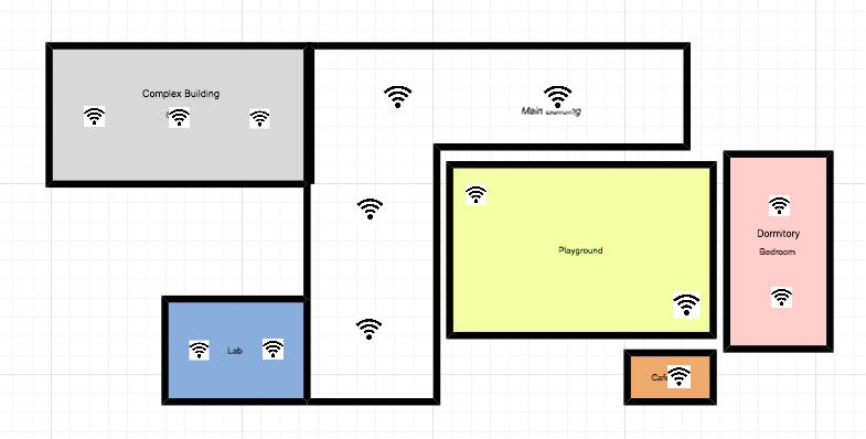
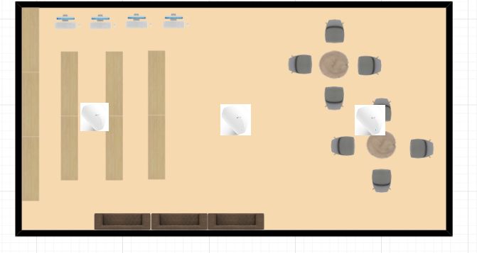
18

is the student's learning requirements. Students can access information re-
sources, submit assignments or conduct group activities in a WLAN environ-
ment. The third is the number of ports requirements. There are many of the
existing network terminal equipment in campus. And, there are large demand
of network ports in library or classroom environment. The WLAN will meet the
needs of information points. The fourth is the construction wiring requirements.
The WLAN allows smooth communication between various buildings in campus.
The wireless networks can coverage the signals to the places where there are
difficult to arrangement of wires.

I will design WLAN for five different buildings and one outdoor area. The build-
ings include the main building, complex building, dormitory, cafeteria and the
laboratory building, as shown in Figure 12.

Figure 12. The plan of the campus

There are six floors in the main building, consisting of classrooms and offices.
And, there are eleven floors in the complex building, consisting of the library
and activity rooms. What’s more, there are six floors in the dormitory, two floors
in the cafeteria and eight floors in the laboratory building.
19

3.3   WLAN Topology

In this part I planned a basic topology for the WLAN, as shown in Figure 13.

Figure 13. WLAN topology

In this figure, the core of the campus network is the network center. The router
is connected to the external network and firewall. There are different kinds of
servers connect to the router. I used one core switch connected to the wired
network and the wireless controller connected to the core switch. Then I have
several PoE switches connected to the core switch and access point connect
to the PoE switches. PoE refers to Power over Ethernet and it is a technology
that lets network cables carry electrical power. It means that only one cable is
enough for the PoE switch to provide network and power connection at the
same time. Then the APs will spread out the wireless signals so that all the
clients in the coverage area are able to access the WLAN.
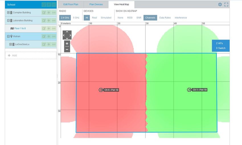
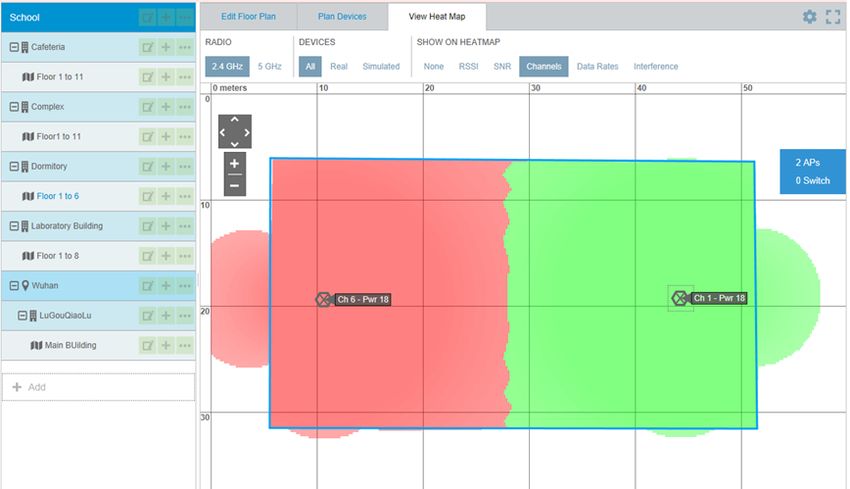
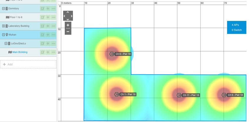
20

3.4   Channel Management

I introduced channels in the theory part and here I will elaborate which channel
I will use for each building by using the HiveManager NG tool. And, I will also
explain why I select that channel. Here I planned channels for each building.
For the main building, each floor uses 4 APs and all the APs work on the 2.4GHz
bandwidth, so I used the channels 1, 6 and 11. As shown in Figure 14, channels
will not overlap each other. What’s more, I used different permutations to man-
age the APs for each floor. It means that I used different channels for the same
locations of the neighboring floors. I will also use this method for other buildings.

Figure 14. Channel management for the main building

For the laboratory building, each floor uses 2 APs and all the APs work on the
2.4GHz bandwidth, so I selected channel 1 and channel 6. As shown in Figure
15, red and green colors show that the channels will not overlapping each other.

Figure 15. Channel Management for Laboratory Building
21

For the cafeteria, one AP is required for each floor and I used different channels
in different floors. I used channel 1 for the first floor, as shown in Figure 16 and
I use channel 6 for the second floor. So the channels will not overlapping each
other.

Figure 16. Channel Management for Cafeteria

For the dormitory building, each floor uses 2 APs and all the APs work on the
2.4GHz bandwidth, so I decided to use channel 1 and channel 6. As shown in
Figure 17, red and green colors show that the channels will not overlap each
other.

Figure 17. Channel Management for Dormitory
22

For the complex building, each floor uses 3 APs and all the APs work on 2.4GHz
bandwidth, so I decide to use channel 1, channel 6 and channel 11. As shown
in Figure 18, different colors clear reality that the channels will not overlapping
each other.

Figure 18. Channel Management for Complex Building

If there are channels that overlap each other, it will cause interference between
signals. Then there is slower throughput and packet loss at the same time.
That’s the reason why channel management is needed here.

3.5   AP Management

In this part I will introduce how many APs are used for each building and where
I decided to place them. The 2.4GHz frequency is used for each APs, because
there are many walls or other objects in each building and I need better cover-
age of the WLAN. What’s more, in the campus environment, I don't need to care
about some 2.4GHz household appliances interferencing the network. Floor-
planner and HiveManager NG are used in this chapter for AP management.

For the main building, the main coverages of the networks are classrooms. In
this case, I used ceiling APs and planned 4 APs for each floor, as shown in
Figure 19. The model of the AP is TL-AP1750C-PoE from TP link company. It’s
23

easy for IT managers to manage the APs, if all the APs are of the same model.
So, I used the same model for all indoor places. This model of AP has a built-in
directional antenna and it can improve the signal quality of the coverage area,
especially where there is a need for penetration. Each AP can support 80 clients’
access in the network at the same time. I decided to install the APs on the ceiling
of the corridor, near the window or the door of the classrooms.

Figure 19. AP Management for the Main Building

The lab building has seven floors. I used 2 APs for each floor, as shown in
Figure 20. The model of the AP is TL-AP1750C-PoE. The main coverage areas
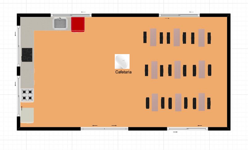
24

are each laboratory and corridors. I decided to install the APs on the ceiling of
the corridor, close to the laboratory. Some specific needs have to be determined
according to the network cabling situation.

Figure 20. AP Management for the Laboratory

The cafeteria has two floors. I used one AP for each floor, as shown in Figure
21. The signal will transmit well, because there is a large open area in the caf-
eteria. The type of the AP is ceiling AP and the model is TL-AP1750C-PoE. I
25

decided to install the APs in the middle of the ceiling. One AP used, full cover-
age achieved.

Figure 21. AP Management for the Cafeteria

The complex building has 11 floors and it is the second biggest building in the
campus. The library and some wide range activities room is inside the building.
In this case, I put 3 APs for each floor, as shown in Figure 22. The model of the
AP is TL-AP1750C-PoE. I decided to install the APs in the ceilings, depending
on the environment of each floor.
26

Figure 22. AP Management for the Complex Building

For the dormitory, I considered the coverage of each room. Actually I planned
two ways to place the APs. The first one is by using ceiling APs in the aisle and
the other is by using panel APs in every room. Considering the budgets and the
real situation, I found that I didn’t need that many APs. Only ceiling APs are
enough for the network coverage. So, in this building I used 2 ceiling APs for
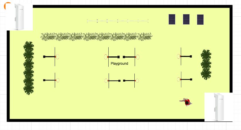
27

each floor, as shown in Figure 23. The model of the APs is TL-AP1750C-PoE.
Because of It’s stronger penetration.

Figure 23. AP Management for the Dormitory

The last coverage area is outdoor place. When I selected an outdoor AP, I had
to consider the location, the range of service, the power supply, the coverage
of the network, the rate of the network and whether it would be easy to install
and manage. The model I used is TL-AP300P from the TP-LINK company. The
TL-AP300P is a high power AP for the outdoor place and it can work at any
harsh environment. I will introduce the model in later chapters. I decided to use
the 5GHz band for the outdoor place, because there are no obstacles. I decided
28

to install the APs at the diagonal corner of the playground, as shown in Figure
24.

Figure 24. AP management for the playground

3.6   Security of the WLAN

The use of broadcast in WLAN may cause a security problem. Planning for the
security of the campus wireless local area network is a complex thing. Some of
the hackers might corrupt data without promise. To solve the problem, WLANs
always need user authentication and data privacy. Securing the network pro-
tects the organizations from threats and controls who can access the network.
So, for the security part, I will assign VLAN for each building, and then I will use
portal authentication to control the access to the WLAN. As Table 4 shows, each
building has its own VLAN number and I also configure IP for each place, but I
still need discuss it with the school, if I can use these IPs or not. The table clearly
shows how many floors I have for each building and how many APs I used for
each floor.
29

Table 4. Division of VLAN

  Building     VLAN         IP          Gateway           Floor   AP

                                                           1      4

                                                           2      4
   Main
                101     192.168.101.0   192.168.101.254    3      4
   Building
                                                           4      4
                                                           5      4
                                                           6      4
                                                           1      2
                                                           2      2
                                                           3      2
                                                           4      2
  Complex                                                  5      2
  Building      102     192.168.102.0   192.168.102.254    6      2
                                                           7      2
                                                           8      2
                                                           9      2
                                                           10     2
                                                           11     2
                                                           1      2
                                                           2      2
                                                           3      2
  Laboratory                                               4      2
  Building      103     192.168.103.0   192.168.103.254    5      2
                                                           6      2
                                                           7      2
                                                           8      2
                                                           1      2
                                                           2      2
                                                           3      2
  Dormitory     104     192.168.104.0   192.168.104.254    4      2
                                                           5      2
                                                           6      2
                                                           1      1
  Cafeteria     105     192.168.105.0   192.168.105.254
                                                           2      1
  Playground    106     192.168.106.0   192.168.106.254    1      2

  Total                                                           78
30 For the authentication, I used the portal authentication to control the access to the network. With portal authentication, all the students and teachers must log in to the portal website, and then each of them might access the portal website. And if they want to access the internet, they have to pass the portal authentica- tion on the portal website. The benefit is that it authenticates clients directly through the web page, without the use of any client software. It’s for the IT man- ager to manage the clients. 3.7 Lists of Hardware and Budgets For the campus WLAN, I have to consider about the hardware from all sides. When selecting the APs, I considered the following sides: the first ones are the environmental characteristics, whether the AP is used in an indoor area or an outdoor area. The second is the way of installation, whether to install on the ceiling or panel. The third is the power supply, whether it is standard PoE or passive PoE. The Forth is the coverage of the WLAN, whether it is a single room or multiple rooms. How many clients will access each AP. All of the hard- ware is manufactured by the TP-LINK company from China, as they are much suitable for the real situation of this project. I selected TL-AP1750C-PoE as the model of indoor AP, as shown in Figure 25. TL-AP1750C-PoE is one kind of ceiling AP from the TP-LINK company. It can work in 2.4GHz or 5GHz bands and more clients are allowed to access the AP than the parity price of the other APs. This model of AP has built-in directional antenna in order to improve the signal quality of the coverage area. In the com- plex environment, we can increase the AP transmit power to enhance the cov- erage effect of the WLAN. According to the needs of the building, this model of AP can be installed on the ceiling or wall. It uses standard PoE for power supply and each AP only need one network cable. It is convenient for construction. The price of this model is EUR 120. Figure 25. TL-AP1750C-PoE AP TP-LINK 2017
31

The hardware specifications and software specifications of the model
TL-AP1750C-PoE AP are shown in Table 5.

Table 5. Hardware and software specifications of TL-AP1750C-PoE

Hardware specifications
Product number            •   TL-AP1750C-PoE
Installation              •   Ceiling Mounting
Size                      •   264 * 241 * 55mm
                          •   2.4GHz Frequency Band: 450Mbps
Wireless
                          •   5GHz Frequency Band: 1300Mbps
Port                      •   One 10/100 / 1000M RJ45 port
Power supply              •   PoE Power Supply
Total power consumption   •   15.31W
                          •   Operating Temperature: 0 ℃ ~ 40 ℃
                          •   Operating Humidity: 10% to 90% RH Non-condensing
Use of the environment
                          •   Storage Temperature: -40 ℃ ~ 70 ℃
                          •   Storage Humidity: 5% to 90% RH Non-condensing
Software specifications
                          •   SSID Broadcast: Supported
                          •   Network Type: Guest network, Employee network
                          •   Wireless Encryption: WEP, WPA, WPA2, WPA-PSK,
                              WPA2-PSK
Wireless                  •   User Isolation: Isolation between wireless networks, AP in-
                              ternal isolation
                          •   VLAN Settings: support SSID and Tag VLAN binding
                          •   Transmit Power Setting: Supports 1dBm linear regulation
                          •   Number of Wireless clients: Restricted
The number of clients
                          •   100
that can be associated
                          •   System Log: Yes
                          •   Factory Reset: Supported
                          •   Backup Configuration: Supported
System management         •   Import Configuration: Supported
                          •   Software Upgrade: Support

I selected TL-AP300P as the outdoor AP for the WLAN, as shown in Figure 26.
TL-AP300P is a model of high power AP for outdoor place. It uses ASA outdoor
plastic shell and professional components in order to possessing good proper-
ties for damp-proof, dustproof, anti-statics, shocking-resistance and lightning
protection. It will adapt to wind, sun, rain, snow and other harsh environments.
It will operate properly even in the extreme high and low temperature (-30 ° C ~
70 ° C) environment. TL-AP300P provides 300Mbps transmission rate and it
has built-in 9dBi high-gain dual-polarized antenna, so that it has stronger signal
and a wider range covering area. TL-AP300P has 500mW emissive power and
32
-95dBm acceptance sensitivity, and is especially suitable for outdoor long-dis-
tance WLAN applications. It uses passive PoE cable for power supply and 60
meters electric power transmission. The price of the model is EUR 70.
Figure 26. TL-AP300P AP (TP-LINK 2017)
The hardware specifications and software specifications of the model
TL-AP300P AP are shown in Table 6.
Table 6. Hardware and software specifications of TL-AP300P AP
Hardware specifications
Product number • TL-AP300P
Installation • Pole installation
Size • 224 * 79 * 60mm
• Working frequency band: 2.4GHz-2.483GHz (China)
Wireless
Wireless rate: 300Mbps
Power supply • 24VDC / 1A Passive PoE power supply, distance of 60M
• 6kV lightning protection, 15kV ESD protection
Environmental
ASA engineering plastic housing, IP55 grade dustproof,
protection
waterproof
• Operating temperature: -30 ~ 70
• Operating humidity: 10% to 90% RH non-condensing
Use of the environment
• Storage temperature: -40 ~ 70
• Storage humidity: 5% to 90% RH non-condensing
Software specifications
• SSID Broadcast: Supported
• Network type: Guest network, employee network
• Wireless encryption: WEP, WPA, WPA2, WPA-PSK, WPA2-
PSK
Wireless
• User isolation: isolation between wireless networks, AP inter-
nal isolation
• VLAN settings: support SSID and Tag VLAN binding
• Transmit power setting: Supports 1dBm linear regulation
The number of clients
• 100
that can be associated
• System Log: Yes
• Factory Reset: Supported
System management
• Backup Configuration: Supported
• Import Configuration: Supported33
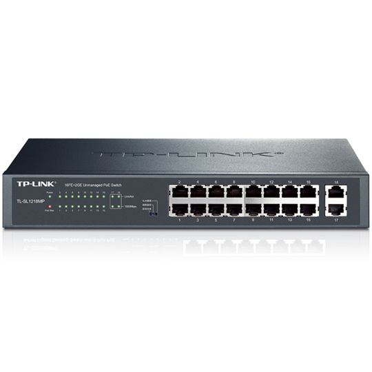
I selected TL-SL1218MP as the model of access switch, as shown in Figure 27.
TL-SL1218MP is a PoE switch designed by the TP-LINK company. It will pro-
vide standard switching, video monitoring and VLAN isolation. The manage-
ment and maintenance of the switch is simple. And, It's designed to meet the
requirements of a medium sized enterprise, community, hotel, office network
and campus to set up their cost-effective network. The price of the PoE switch
is EUR 150.
Figure 27. TL-SL1218MP switch (TP-LINK 2017)
The hardware specifications and software specifications of the model
TL-AP300P AP are shown in Table 7.
Table 7. Hardware and software specifications of TL-AP1750C-PoE
Hardware specifications
Product number • TL-SG5428
Size • 290* 180* 44 mm
• 16 10 / 100Mbps RJ45 ports, support PoE power supply
Port
• 2 10/100 / 1000Mbps RJ45 ports
• Operating temperature: 0 ℃ ~ 40 ℃
• Operating humidity: 10% to 90% RH non-condensing
Use of the environment
• Storage temperature: -40 ℃ ~ 70 ℃
• Storage humidity: 5% to 90% RH non-condensing
Software specifications
• M1: Standard switching
Basic features • M2: Video monitoring
• M3: VLAN isolation
I selected TL-AC100 as the wireless controller of the WLAN, as shown in Figure
28. TL-AC100 is one of the TP-LINK wireless controller products designed for
hotels, enterprises, schools, shopping malls and restaurants. And, it can be uni-
fied to manage up to 100 TP-LINK ceiling APs and panel APs. It can meet a
wide range of wireless engineering requirements. TL-AC100 regularly collects34
the working status of each AP, and, as all the APs’ working state will be dis-
played on the interface in an intuitive way, it’s easy for IT managers to manage
the APs. IT managers can unified upgrade all the APs’ software through TL-
AC100 in order to avoid the trouble of a separate upgrade. It will reduce the
complexity of maintenance. In my case, I have 78 APs for the campus, so it’s a
good idea to select TL-AC100 as the wireless controller when considering the
efficiency and cost at the same time. The price of the wireless controller is EUR
50.
Figure 28. TL-AC100 wireless controller (TP-LINK 2017)
The hardware specifications and software specifications of the model
TL-AC100 wireless controller are shown in Table 8.
Table 8. Hardware and software specifications of TL-AP1750C-PoE
Hardware specifications
Product number • TL-AC100
Size • 209* 126 * 26mm
Port • 5 10/100M RJ45 ports
• Operating temperature: 0 ℃ ~ 40 ℃
• Operating humidity: 10% to 90% RH non-condensing
Use of the environment
• Storage temperature: -40 ℃ ~ 70 ℃
• Storage humidity: 5% to 90% RH non-condensing
Software specifications
• SSID Broadcast: Supported
• Network type: Guest network, employee network
• Wireless encryption: WEP, WPA, WPA2, WPA-PSK, WPA2-
PSK
Wireless
• User isolation: isolation between wireless networks, AP inter-
nal isolation
• VLAN settings: support SSID and Tag VLAN binding
• Transmit power setting: Supports 1dBm linear regulation
The number of clients
• 100
that can be associated
• System Log: Yes
• Factory Reset: Supported
System Management • Backup Configuration: Supported
• Import Configuration: Supported
• Software Upgrade: Support35
I selected the TL-SG5428 as the core switch of the WLAN, as shown in Figure
29. The TL-SG5428 is a gigabit three-tier network management switches that
TP-LINK company designed for high-security high-performance network. It sup-
ports RIP, static routing, DHCP server, DHCP relay, ARP proxy. It will provides
comprehensive security policy, perfect QoS strategy and VLAN function. It is
easy to manage and maintenance. It can be acts as the core switch of medium
enterprises, residential, hotel and campus network, in order to meet the high
performance, stable, reliable and affordable network needs. The price of this
model is EUR 350.
Figure 29. TL-SG5428 core switch (TP-LINK 2017)
The hardware specifications and software specifications of the model
TL-SG5428 core switch are shown in Table 8.
Table 9. Hardware and software specifications of TL-SG5428 core switch
Hardware specifications
Product number • TL-SG5428
Size • 440* 180* 26mm
Port • 5 10/100M RJ45 ports
• Operating temperature: 0 ℃ ~ 40 ℃
• Operating humidity: 10% to 90% RH non-condensing
Use of the environment
• Storage temperature: -40 ℃ ~ 70 ℃
• Storage humidity: 5% to 90% RH non-condensing
Software specifications
• SSID Broadcast: Supported
• Network type: Guest network, employee network
• Wireless encryption: WEP, WPA, WPA2, WPA-PSK, WPA2-
PSK
Wireless
• User isolation: isolation between wireless networks, AP inter-
nal isolation
• VLAN settings: support SSID and Tag VLAN binding
• Transmit power setting: Supports 1dBm linear regulation
The number of clients
• 100
that can be associated
• System Log: Yes
• Factory Reset: Supported
System Management • Backup Configuration: Supported
• Import Configuration: Supported
• Software Upgrade: Support36 It is important to select suitable hardware for the campus WLAN. All the hard- ware should meet the needs and the real situation of the WLAN. For the cam- pus, always ensure high performance WLANs and save cost at the same time. The cost for the list hardware of the WLAN was about EUR 10000, except wires and all the other installation fee. 4 CONCLUSION We are now in a new era of information and it has become the core factor of social and economic development. Information technology has become the trend of the world. The use of the networks is more closely linked to human society, political, economic and daily work, and all aspects of life. What’s more, the computer networks will be destined to become the most important infra- structure for the 21st century global information society. The WLAN is the product that combine computer technology and wireless com- munication technology. It brings a lot of convenience to people's lives. The aim of the project was to create a WLAN for campus. In theory part I gained deep knowledge of the features of WLANs, including the advantages and limitations of WLANs, technical standards of WLANs, security and authentications of WLANs, components of WLANs and different kind topologies of WLANs. After that, I successfully built a topology for the WLAN in the practical part by using the VISIO tool. I also managed channels and APs by using HiveManager NG. Then, I selected the suitable security methods and hardware for the WLAN. There were still some difficulties left during the implementation of this project. For example, how to deploy APs in a real environment, how to calculate the attenuation power according to the material of the barrier and what kinds of software should be installed in the WLAN? What’s more, in this project I just defined an abstract concept for WLAN. If you want to build WLANs, you need an IT group to discuss and consider more about the project, it is not an easy job
37

in the real environment, you have to consider about all the hardware and soft-
ware at the same time. With the progress and continuous innovation of network
technology, WLANs still play an important role in our daily life for many aspect.
38

REFERENCE

Bradley, M. 2017. Wireless Standards 802.11a, 802.11b/g/n, and 802.11ac.
WWW document. Available at: https://www.lifewire.com/wireless-standards-
802-11a-802-11b-g-n-and-802-11ac-816553[Accessed 01 April 2017].

Bradley, M. 2017. What Hardware Is Required to Build a Wireless Network?
WWW document. Available at: https://www.lifewire.com/required-to-build-wire-
less-networks-816542 [Accessed 01 April 2017].

Karen, S and Derrick, D. 2007. Wireless Network Security for IEEE
802.11a/b/g and Bluetooth. PDF document. Available at: http://citese-
erx.ist.psu.edu/viewdoc/download?doi=10.1.1.109.6200&rep=rep1&type=pdf
[Accessed 01 April 2017].

Abdelkarim, R. 2006. Security in Wireless Data Networks: A Survey Paper.
WWW document. Available at http://www.cs.wustl.edu/~jain/cse574-
06/ftp/wireless_security/index.html[Accessed 20 April 2017].

Stefan, P and Vladimir, W. 2012. Wireless Mesh Networks - Efficient Link
Scheduling, Channel Assignment and Network Planning Strategies.
WWW Document. Available at :http://www.intechopen.com/books/wireless-
mesh-networks-efficient-link-scheduling-channel-assignment-and-network-
planning-strategies/channel-assignment-schemes-optimization-for-multi-inter-
face-wireless-mesh-networks-based-on-link-loa [Accessed 08 March 2017].

Cisco. 2008. Authentication Types for Wireless Devices. WWW document.
Available
at :http://www.cisco.com/c/en/us/td/docs/routers/access/wireless/software/guid
e/SecurityAuthenticationTypes.html [Accessed 25 April 2017].

Alexandra, G. 2015. Getting Familiar with Wi-Fi Channels? WLAN Back to Ba-
sics. WWW document. Available
at :http://boundless.aerohive.com/experts/WLAN-Channels-
Explained.html[Accessed 26 March 2017].

Cisco. 2011. Wireless LAN Controller Web Authentication Configuration
Example. WWW document. Available
at :http://www.cisco.com/c/en/us/support/docs/wireless-mobility/wlan-
security/69340-web-auth-config.html [Accessed 20 April 2017].

H3C. Portal Authentication Technology White Paper.
WWW document. Available at :http://www.h3c.com.hk/Products___Technol-
ogy/Technology/Secu-
rity_and_VPN/Technology_White_Paper/200809/617218_57_0.htm[Accessed
08 March 2017].
39

RF Wireless World. no date. WEP vs WPA vs WPA2 . WWW Document.
Available at: http://www.rfwireless-world.com/Terminology/WEP-vs-WPA-vs-
WPA2.html[Accessed 02 April 2017].

Difference Between. no date. Difference between Wireless LAN and Bluetooth.
WWW Document. Available at:http://www.differencebetween.info/difference-
between-wireless-lan-and-bluetooth [Accessed 12 March 2017].

Abby, S. 2014. WHAT IS A WLAN CONTROLLER (PART 1) . WWW Docu-
ment. Available at:http://boundless.aerohive.com/blog/what-is-a-wlan-control-
ler-part-1.html[Accessed 12 April 2017].

Brent, A. 2001. HomeRF and Bluetooth Wireless Communication Compared.
WWW Document.          Available at:  http://www.informit.com/articles/arti-
cle.aspx?p=24265&seqNum=4[Accessed 02 April 2017].

National Instruments. 2015. WLAN - 802.11 a, b, g and n. WWW Document.
Available at:http://www.ni.com/tutorial/7131/en/[Accessed 08 March 2017].

Mark, C. 2013. CWNA Guide to Wireless LANs. WWW Document. Available at: h
ttps://books.google.fi/books?id=VbAKAAAAQ-
BAJ&pg=PA168&lpg=PA168&dq=FHSS+DSSS+WLAN&source=bl&ots=8uVK
cTsKBr&sig=EXwMq0qaDGrsO5jZrTUUlg2cbtU&hl=zh-
CN&sa=X&ved=0ahUKEwjw_b_7p6fTAhWC3iwKHXsxCfcQ6AEIcjAJ#v=onep
age&q=FHSS%20DSSS%20WLAN&f=false [Accessed 26 March 2017].

Samraiz, T. 2014. Bluetooth. WWW Document. Available at: https://www.sli-
deshare.net/Samraiz1/bluetooth-32312039[Accessed 02 April 2017].

Animasigaia. 2014. NETWORKING AND COMMUNICATIONS. WWW Docu-
ment. Available at:
https://animasigaia.wordpress.com/2014/11/26/networking-and-
communications/ [Accessed 28 April 2017].

Wikipedia. 2017. Wireless LAN controller. WWW Document. Available at:
https://en.wikipedia.org/wiki/Wireless_LAN_controller [Accessed 28 April
2017].

Microsoft. 2003. How 802.11 Wireless Works. WWW Document. Available at:
https://technet.microsoft.com/en-us/library/cc757419(v=ws.10).aspx [Ac-
cessed 28 April 2017].

Metageek. no date. Why Channels 1, 6 and 11? WWW Document. Available
at: http://metageek.com/training/resources/why-channels-1-6-11-
2.html?utm_expid=190328-
189.BCYMV3QrTsW_lMQM0PlqcA.1&utm_referrer=https%3A%2F%2Fwww.g
oogle.fr%2F [Accessed 28 April 2017].
You can also read