THE COMMON INFORMATION MODEL - AN INTRODUCTION TO IEC 61970-301 & 61968-11: DR ALAN W. MCMORRAN
←
→
Page content transcription
If your browser does not render page correctly, please read the page content below

An Introduction to IEC 61970-301 & 61968-11:

     The Common Information Model

                     Dr Alan W. McMorran
             Institute for Energy and Environment
       Department of Electronic and Electrical Engineering
                    University of Strathclyde
                           Glasgow, UK

                          January 2007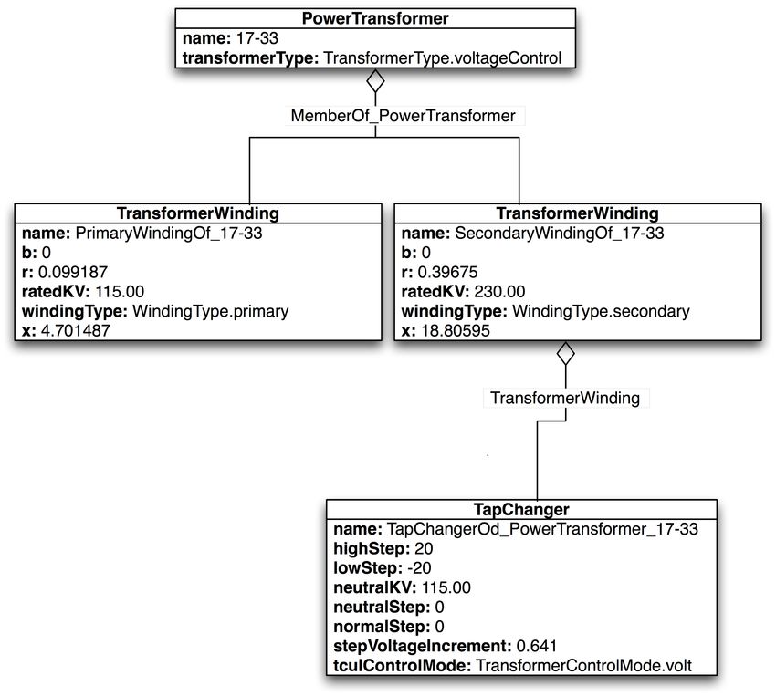
The copyright of this publication belongs to the author under the terms of the United
Kingdom Copyright Acts. Due acknowledgement must always be made of the use of
any material contained in, or derived from, this publication.
1     Background

1.1 Introduction
Since deregulation, both in the UK and internationally, there has been an increasing
need for power companies to exchange data on a regular basis. This is to ensure the
reliable operation of the interconnected power networks owned and operated by a
number of different utilities.     Power companies use a variety of different formats to
store their data, whether it be asset and work scheduling information in a proprietary
internal schema within a database, topological power system network data within a
control system, or static files used by simulation software.
While much of this data is only required within a company, there is often a need to
exchange the data both internally between different applications and externally with
other companies. The large number of proprietary formats used by these applications
requires a myriad of translators to import and export the data between multiple
systems. This exponential growth in complexity when integrating increasing numbers
of applications and exchanging between multiple companies has driven the requirement
for a common format that covers all the areas of data exchange in the power electrical
domain.
The IEC standard 61970-301 [1] is a semantic model that describes the components of a
power system at an electrical level and the relationships between each component. The
IEC 61968-11 [2] extends this model to cover the other aspects of power system software
data exchange such as asset tracking, work scheduling and customer billing. These two
standards, 61970-301 and 61968-11 are collectively known as the Common Information
Model (CIM) for power systems and currently have two primary uses: to facilitate the
exchange of power system network data between companies; and to allow the exchange
of data between applications within a company.
The development of the CIM has primarily taken place in North America, where the
North American Electric Reliability Council (NERC) has adopted the CIM as the format
for exchanging network data between transmission companies. The majority of the
application integration activities have similarly taken place within North American
utilities.
This paper describes the pitfalls of the traditional methods of storing power system
data, then introduces the concepts behind class modelling and how this approach is
used to define a power system in the IEC 61970 Common Information Model (CIM)
standard. The use of the Extensible Markup Language (XML) to encapsulate this data
for the exchange of both full power system models and inter-application messages is
then described.

1.2 Power System Data Formats
Since the advent of the modern digital computer, power system engineers have utilised
the capabilities of this tool in a variety of areas, whether it be performing complex
analysis calculations on a power system or to control its operations in real-time. All of
these applications require the operator to digitally store and exchange data about the
system.
Large-scale Energy Management Systems (EMS) and asset-management systems use
database schemas for defining the structure of the data storage data, often custom-
written to reflect the operator’s specific requirement. Offline applications for performing
load-flow and fault-level analysis simulations use application-specific file formats that
represent the data required by each application.
In modern utilities’ IT infrastructures, large-scale applications such as the EMS and
asset-management system communicate with each other, generally using a vendor’s
own custom format based on the internal database schema. In the past this often
required the user to purchase each piece of enterprise-level software from the same
vendor to ensure compatibility when integrating them.
The deregulation of the power industry, however, has resulted in multiple utilities,
running software from a number of different vendors, having to exchange large data
sets on a regular basis. The use of proprietary, custom formats complicates this
exchange, requiring complex translation between each of the custom formats.
Similarly, offline applications traditionally use a rigid, proprietary format containing
only the data required by that particular version of the application. When subsequent
versions of the program require additional details the file format is changed, resulting in
multiple formats for a single application. Of course, such a scenario is not limited to
power system applications. Changing the file format for each new software version is
common practice within the software industry but usually only causes minor irritation
since each new version of a vendor’s software contains import facilities to convert
previous versions of the file format into the new format.
Problems occur when companies need to exchange data between software applications
from different vendors, and/or have multiple versions of the same software running
within their company. Such a scenario requires a company to either:
1. Maintain multiple copies of the same data in multiple formats
2. Store the data in a format compatible with every piece of software, requiring the
removal of application-specific data and a subsequent loss in precision
3. Store the data in a single, highly-detailed format and create software to translate
from this highly-detail format to the desired application file formats
4. Use a highly detailed format that is compatible with every application and whose
standard format contains the basic data required to represent the power system
while simultaneously allowing additional, detailed, application-specific data to
be contained without invalidating the format.
The third option requires additional software engineering on the part of the company to
create translation tools, but requires them to maintain only a single format containing all
the data required. The fourth option represents the ideal solution, allowing a company
to maintain a single, highly detailed format that is compatible with any of their
software.
This option does, however, requires three things:
A highly detailed model to describe the power system
A file format capable of storing extended data without affecting the core data
Power system software vendors and utilities to either adopt and embrace this
data model and format either for economic or regulatory reasons
The Common Information Model (CIM) for Power Systems has the potential to meet the
first requirement of the above list while the eXtensible Markup Language (XML),
combined with the Resource Description Framework (RDF) offers a means of fulfilling
the second requirement. The remaining requirement can be considered more of a
commercial challenge than a technical one. Universal acceptance of this format requires
both utilities and vendors to acknowledge the benefits of adopting the standard. At
present, all of the major power system application vendors are active participants in the
CIM Interoperability tests and the popularity of the format is spreading.
This paper will provide some background on the CIM and the CIM RDF XML format.
To understand the structure of the CIM, however, it is important to have an
understanding of class hierarchies within the object-oriented software paradigm and the
benefits of using such an approach to model the components of a power system. The
following sections will provide some general background on class hierarchies, followed
by more detailed background information on the CIM. Finally, it will be shown how this
data can be represented in the RDF XML format.

2 Class Hierarchies and UML Class Diagrams
When building any system to represent data, whether it be a software architecture or a
database schema, the design of the system will define how extensible and scalable the
system is, and ultimately, whether it succeeds or fails at its given task. This paper
provides an introduction to the concept of Class Hierarchies and how they are used in
system design, along with the Unified Modelling Language (UML).
Within a system, a class represent a specific type of object being modelled. A class
hierarchy is an abstract model of a system defining every type of component within a
system as a separate class. A class hierarchy should reflect the real-world structure of
the system.
While a full description of UML is outwith the scope of this thesis, UML class diagrams
provide a useful means of visually representing object hierarchies. This section will
provide a simple case study to show how a class hierarchy representing a small segment
of a University system can be constructed independently of the final platform on which
the design will be utilised.

2.1 Classes
Each class can have its own internal attributes and relationships with other classes. Each
class can be instantiated into any number of separate instances, known as objects, each
containing the same number and type of attributes and relationships, but with their own
internal values.

     Figure 2.1 The Person Class
A simple example of a class is that of a Person as shown in Figure 2.1. The Person class
contains two basic attributes: Name and Gender. If the system being created were to
represent every person in the University, it would require only this single class since
every person within the University can be represented at the most basic level by the
attributes defined in Person.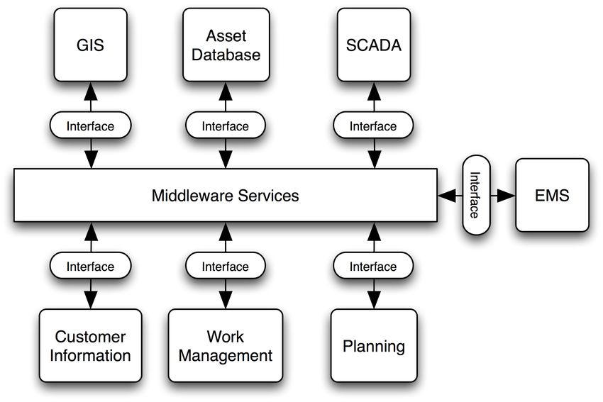
For a University containing 10,000 students and staff, the system would create 10,000
separate instances of the Person class, each containing a value for Name and Gender
independent of the other 9,999 instances (although not necessarily unique).
If the system is required to store more information than just a person’s Name and
Gender, and differentiate between staff, students and the different types of each, then
the class diagram becomes more complex.

2.2 Inheritance (Generalisation)
Inheritance (also known as Generalisation) defines a class as being a sub-class of another
class. As a sub-class, it inherits all the attributes of its parent, but can also contain its
own attributes.

     Figure 2.2 Class Hierarchy of people at a University
Figure 2.2 provides a class hierarchy to represent some of the different types of people
that exist within a University system. This diagram, as with all subsequent class
diagrams uses standard UML symbology. Student and Staff are both sub-classes of
Person. A Student is still a person and still has a Name and Gender, but has additional
attributes to denote the year they are in, their student number and the course they are
studying. Similarly, if someone is Staff they are still a Person, but have gained a new
attribute to indicate their salary.
The Student class itself has two sub-classes, Undergraduate and Postgraduate, both
inheriting all the attributes of Student (and in turn, of Person), but independent of each
other. The Postgraduate class also has two subclasses, Masters and PhD. A PhD is a
Postgraduate and a Student and a Person, with all of their attributes, but with the
addition of its own ResearchTopic attribute.
The Staff class also has two sub-classes, Research and Academic, both of which retain all
the attributes of Staff and Person.
So while a PhD is a Postgraduate, a Student and a Person, not all Students are PhDs.
Similarly, an Academic is Staff and a Person, but not every member of Staff is an
Academic.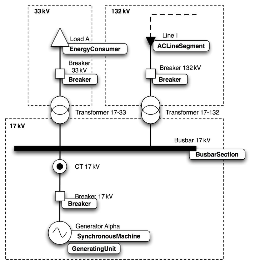
2.3 Association
Section 2.2 has shown how a class hierarchy can be formed to describe sub-classes of
Person, but other than the inheritance there are no other relationships defined between
classes the classes in Figure 2.2.

     Figure 2.3 Class hierarchy of students, staff and subjects
In Figure 2.3 we have introduced two additional classes: Subject and Period. Neither of
these classes are a type of Person, and as such do not inherit from the Person class. The
Subject class does however, have a relationship with the Undergraduate and Academic
classes.
An Undergraduate can study a number of subjects and an Academic can teach a number
of subjects. These relationships are shown on the diagram as associations between the
classes.
For the Undergraduate-Subject association, the role is given as “Studies” while the
location of the arrowhead indicates that it is the Undergraduate who Studies the Subject
(if the arrow were reversed, it would mean that the Subject studied the Undergraduate).
At each end of the association link is the multiplicity. For the Undergraduate-Subject
association, these indicate that a Subject must have from 1 to many (1..*)
Undergraduates, but an Undergraduate can have from 0 to many (0..*) subjects (since it
is possible that some Undergraduates may not be studying any subjects due to
industrial placements, sabbaticals etc. It is assumed that a subject will not exist in the
system if no students have chosen to study it).
Similarly, a Subject will have from 1 to many Academics who teach that Subject, but an
Academic may teach from 0 to many Subjects (since not all Academics have to teach).
The other additional class, Period, with Day, Time and Duration attributes, represents a
particular timetable period and as such a Subject has an association with a Period. As
with the other associations, the Subject-Period association has a role, isTaughtDuring and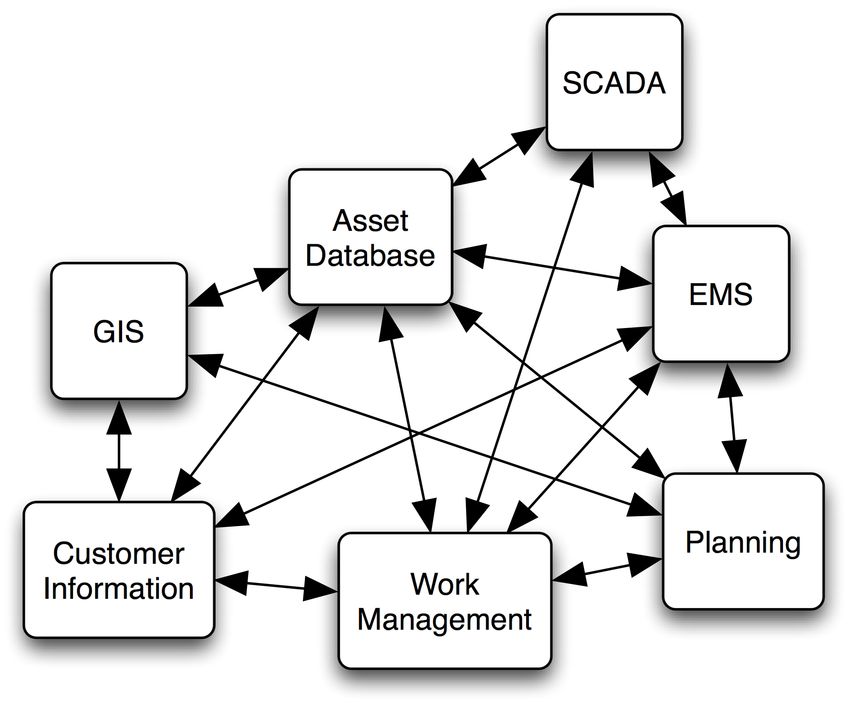
multiplicities which indicate that a Subject will be taught during 1 to many periods and
that a Period will have from 0 to many Subjects taught during its time-period.
This demonstrates how classes relate to each other on a very basic level and how UML
Class Diagrams provide a means of graphically displaying these relationships.

2.4 Aggregation

     Figure 2.4 Class Hierarchy of a University and Building
The Aggregation relationship defines a special kind of association between classes,
indicating that one is a container class for the other. In the example shown in Figure 2.4,
two new classes University and Building have been introduced, each very simple classes
containing only a single attribute to denote their name. The multiplicity on the diagram
operates in the same manner as to that of the Association, indicating that a Building can
be part of 0 or more Universities (we are assuming that some Universities operate joint
schools and not every building within the system will necessarily be part of a
University). The second multiplicity indicates that a University can contain 0 or more
buildings (0 if it operates solely by remote learning for example).
Unlike a simple Association relationship the line denoting a relationship on the diagram
contains a diamond instead of an arrowhead. This indicates that the two classes have an
Aggregation relationship. This can be thought of as “The University is made up of 0 or
more Buildings”, indicating that the relationship is stronger than a simple association.
The clear diamond, however, indicates that the two are not completely inter-dependent,
and that if the University were destroyed the buildings would still exist (assuming the
destruction was not a literal demolition but instead indicated that the University had
ceased to exist).

2.5 Composition

     Figure 2.5 Class Hierarchy of a University, Building and Room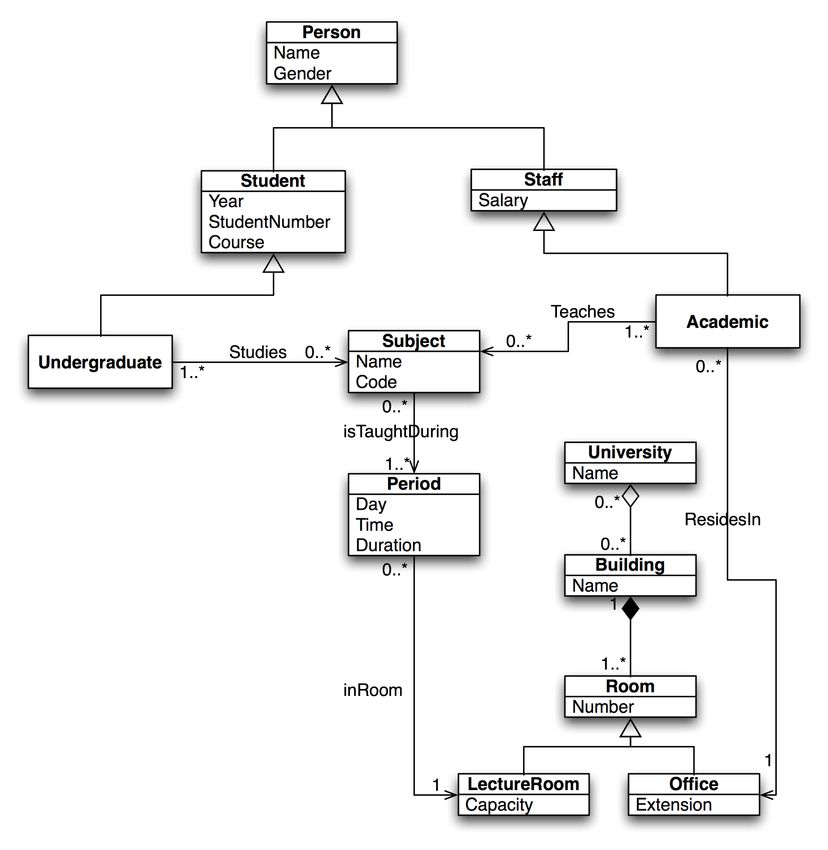
Composition is a specialised form of Aggregation where the “contained” object is a
fundamental part of the “container” object, and that if the “container” is destroyed, all
the objects that are related to it with a composition are similarly destroyed. An example
of this is shown in Figure 2.5 between the new Room class and the Building class.
The line here has a solid diamond, indicating that the relationship is a composition. The
multiplicity states that a building will have 1 or more rooms (since even an empty
building can be thought of as one giant room) and that a room will be contained within
1 building only. This reflects the real world makeup of rooms and buildings. If a
building is destroyed then the rooms within it are also destroyed.
Any system that implements this design will know that if a Building object is destroyed,
any Room objects that are contained within that particular instance will also be
destroyed.

2.6 Summary

     Figure 2.6 Class diagram showing some of previous classes and their relationships
The previous sections should have provided you with a basic understanding of what a
class hierarchy is and how this can be represented on a class diagram. Figure 2.6 shows
some of the classes from the previous sections (along with two extra sub-classes of
Room), and how the separate diagrams in Figure 2.3, Figure 2.4 and Figure 2.5 all relate
to each other. It should be clear that the system could be extended further to
incorporate more details about the University system such as timetables for students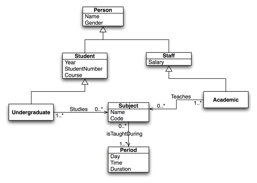
and staff or the computing facilities available in each room. Both of these examples
would make use of the existing classes by association along with the introduction of
new classes.
These fundamentals of the class system are essential in the understanding of the CIM as
described in the following sections.
3 The Common Information Model for Power Systems
This section provides some history of the CIM and how it represents the common
components within a power system. Examples are given to show where a common
power system component fits into the class hierarchy, how connectivity is represented
using CIM classes and how an example circuit, shown as a line diagram, can be
converted to CIM objects. Finally, each of the packages in the IEC 61970-301 standard is
summarised.

3.1 History
Exchanging power systems data between utility companies is always problematic when
proprietary formats are used. In the past, a company would traditionally use a single
software system, whether it is a custom in-house solution, or purchased from a large
software company, and there would be a single proprietary data standard and format
used. With the deregulation of the power industry both in the UK and abroad, there is
now a greater need to be able to share such power system data between companies. The
increase in choice provided by the number of power system software vendors, and the
different software packages and architectures available add to the challenge of data
exchange. These issues point to a requirement for a single, open standard for describing
power system data and to aid the interoperability between software packages and
exchange of information both within one company and between companies.
The Common Information Model (CIM)[1][2] is an open standard for representing
power system components developed by the Electric Power Research Institute (EPRI) in
North America. The standard was developed as part of the IEC TC57 WG13 on
developing a Control Centre Application Programming Interface (CCAPI) to provide a
common model for describing the components in power systems for use in a common
Energy Management System (EMS) Application Programming Interface (API). The
format has been adopted by the major EMS vendors to allow the exchange of data
between their applications, independent of their internal software architecture or
operating platform.
The data model itself is language-independent, defining the components of a power
system as classes along with the relationships between these classes: inheritance,
association and aggregation; and the parameters within each class are also defined. This
provides the foundation for a generic model to represent all aspects of a power system,
independent of any particular proprietary data standard or format. This simplifies the
interoperability between software applications, since there need only exist a translator to
convert to and from the CIM based data, where previously there would have been the
need for translators to convert to and from every other third party company’s
proprietary format.
For an engineer the format of the Common Information Model (CIM) may at first appear
confusing compared with a flat file format. This paper will explain how the CIM was
created using a class structure to describe components of a power system network; the
advantages of this approach; and how a power system network model can be translated
into a number of CIM objects.
3.2 CIM Class Structure
The CIM hierarchy currently has no official common super-class (i.e. a class from which
every component inherits). The majority of CIM classes, however, inherit from the
IdentifiedObject class so for this section it can be considered the base class for the
hierarchy.

3.2.1 Example: The Breaker Class
A simple example will be used to explain why it is advantageous to use a class structure
for defining components instead of simply specifying attributes for every different type
of component in the CIM as an independent entry.
A Breaker is one of the most common components in a power system described as a
“mechanical switching device capable of making, carrying and breaking currents under
normal circuit conditions and also making, carrying for a specified time, and breaking
current under specified abnormal circuit conditions”[1]. To understand how this fits
into the CIM class hierarchy the Breaker can be thought of at different levels of
abstraction.
At the most detailed level it is a Breaker, but since a breaker’s most basic functionality is
the ability to be open or closed it can be described as a specialised type of switch. Within
the power system a switch is part of the physical network that conducts electricity, and
as such can be considered a type of conducting equipment. Since the power system may
contain equipment that does not conduct electricity directly, conducting equipment can
be considered a type of generic equipment. A piece of equipment can similarly be
considered as a being resource within the power system.
A Breaker can therefore be considered to be a Power System Resource, a type of
Equipment, a type of Conducting Equipment and a type of Switch. This corresponds to
a class inheritance structure shown in Figure 3.1 below.
Figure 3.1 Breaker Class Inheritance Hierarchy
The Naming class is the root class for this particular branch of the CIM class hierarchy
and other CIM classes in the Breaker hierarchy are:
PowerSystemResource, used to describe any resource within the power system,
whether it be a physical piece of equipment such as a Switch or an organisational
entity such as a SubControlArea.
Equipment, which refers to any piece of the power system that is a physical
device, whether it be electrical or mechanical.
ConductingEquipment, used to define types of Equipment that are designed to
carry current or that are conductively connected to the network and contains an
attribute to denote the phases (A,B,C,N or any combination of each).
Switch, a generic class for any piece of conducting equipment that operates as a
switch in the network and hence has an attribute to define whether the switch is
normally open or closed.
ProtectedSwitch, a switch that can be operated by protection equipment
Breaker, a specific sub type of ProtectedSwitch, with additional attributes to
define the current rating and transit time.
As with the University system example in Section 2, all subclasses inherit the attributes
from their parent class, and as such a Breaker will contain a normalOpen, from the
Switch class, and phases attribute, from the ConductingEquipment class, as well as its
own native attributes.3.2.2 Subclasses of Switch
As well as Breaker, the CIM standard contains multiple subclasses of Switch, including
Jumper, Fuse, Disconnector, LoadBreakSwitch and GroundDisconnector.
Figure 3.2 Switch class with Breaker and LoadBreakSwitch subclasses
Figure 3.2 shows an example of how the LoadBreakSwitch class, a subclass of
ProtectedSwitch fits into the class hierarchy. Both Breaker and LoadBreakSwitch inherit
from ProtectedSwitch which in turns inherits from Switch, so they both contain a
normalOpen attribute whilst maintaining their own, internal attributes.
As well as dealing with them as their native class, the system can treat a Breaker or
LoadBreakSwitch component as being a ProtectedSwitch, Switch, a piece of Conducting
Equipment, a piece of Equipment, a Power System Resource or just an IdentifiedObject.
For example:
If a piece of software is performing a topological analysis on a power system network
then it will need to know whether a switch is open or closed to determine the status of
the network. The software does not need to know whether the Switch is a Breaker, a
LoadBreakSwitch or any other subtype of Switch since the attribute it is concerned with,
normalOpen, exists in all the classes that inherit from Switch. As the software traverses
the network model, if the component it reaches is of the class Switch or any of its
subclasses it extracts the value of normalOpen and proceeds accordingly.Figure 3.3 Switch Class diagram with new subclasses of Switch and Breaker If a new type of Switch, NewSwitchType is added to the standard at a later date as shown in Figure 3.3, assuming the original Switch class is not modified, then the software will still be able to treat NewSwitchType as if it were a Switch when performing its analysis. Even though the class did not exist when the software was originally written it is looking for any components that are of a class that inherits from Switch. Similarly, if a new subclass of Breaker, NewBreakerType, is added (as shown in Figure 3.3), it is still a type of Switch (since its parent class, Breaker is a subclass of ProtectedSwitch which itself is a subclass of Switch) and can be treated as Switch, ProtectedSwitch or a Breaker by the software. As has been shown, this use of an inheritance hierarchy to define components allows classes within the system to be defined as specialised subclasses of a general parent class until the desired level of detail has been reached, from the generic PowerSystemResource right down to the Breaker or LoadBreakSwitch class. This use of a class hierarchy also allows extensions to be made to the standard by extending the existing classes instead of introducing completely new, independent entries. This approach, as shown, can allow existing software applications to interpret the new data, albeit at a higher level of abstraction, without necessarily requiring extensive modification. 3.2.3 Defining Component Interconnections When defining how components within a power system network join together, rather than define direct connection between components, the CIM uses Terminals and Connectivity Nodes. To understand why this approach is taken consider the very simple, circuit shown in Figure 3.4 below.
Figure 3.4 Connectivity Example circuit
This circuit, containing a Breaker, Load and Line, would require three CIM Objects to
represent the pieces of physical conducting equipment: An Energy Consumer (to
represent the load), a Breaker and an AC or DC Line Segment for the line.
The CIM does not model interconnections by associating each component with the other
components it connects to, since having Breaker 1 contain associations to Load A and
Line Alpha; Load A contain associations to Line Alpha and Breaker 1; and Line Alpha
contain associations to Breaker 1 and Load A would result in the interconnections being
defined as shown in Figure 3.5.

     Figure 3.5 Connectivity Example circuit with direct associations
Instead, the CIM uses a Connectivity Node to connect equipment, so that should three
or more pieces of equipment meet at a T or Star point, the connectivity is accurately
represented as shown in Figure 3.6.

     Figure 3.6 Connectivity Example circuit with Connectivity Node
In CIM, however, pieces of conducting equipment are not directly associated with
Connectivity Nodes. A piece of conducting equipment will have one or more Terminals
associated with it, and these Terminals in turn are associated with a single Connectivity
Node.
Figure 3.7 Conducting Equipment and Connectivity class diagram
The relationship between the Terminal, ConnecitivtyNode and ConductingEquipment
classes is shown in Figure 3.7. Since only pieces of conducting equipment carry current
on the network, the association to the Terminal class is from the ConductingEquipment
class with a multiplicity of 0..n since a piece of conducting equipment can have zero or
more connections to the network. The corresponding Terminal to Conducting
Equipment relationship has a multiplicity of 1 since a Terminal can only ever be
associated with one Connectivity Node. Since the Breaker class (via its Switch class
parent), Energy Consumer and AC or DC Line Segment (via the Conductor class) all
inherit from Conducting Equipment, they too inherit the association relationship with
the Terminal class.
The connectivity relationship between the terminals, conducting equipment and
connectivity nodes is illustrated in Figure 3.8a) below.
a) b)
Figure 3.8 Connectivity Example circuit with Connectivity Node and Terminals
The inclusion of the Terminals may initially seem unnecessary, but as well as defining
connectivity, Terminals are also used for defining points of connectivity-related
measurement in the network such as power flows, currents and voltages.The importance of allowing the measurement point to be defined so exactly can be
shown in Figure 3.8b). In this diagram Breaker 1 has two Terminals associated with it to
represent the two distinct network connection points it would have in a real-world
power system network. If the Breaker is open then the measurement of voltage for the
Breaker will be different at these two points where the Breaker connects to the network.
This would result in an ambiguity if measurement were only defined as being on a
particular component without specific information about which point of connection the
measurement is to be made at.
3.3 Converting a Circuit to CIM Objects
The previous sections have described a small section of the class hierarchy for
describing CIM components and shown how Terminals and Connectivity Nodes are
used to define the interconnection of components within the network. This section will
use a more complex example to show how voltage levels, current transformers, power
transformers and generators are modelled by converting a standard line diagram into
CIM objects.
3.3.1 Identifying the CIM Classes
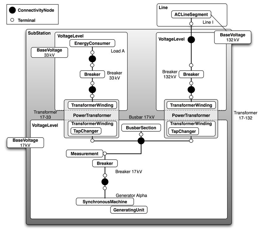
Figure 3.9 Example Circuit as a line diagramThe circuit shown in Figure 3.9 shows a circuit containing a single generating source,
load, line and busbar. The circuit also contains two power transformers resulting in
three distinct voltage levels of 17kV, 33kV and 132kV.
The load, line and breakers, as stated in Section 3.2.3 map to the CIM EnergyConsumer,
ACLineSegment and Breaker classes respectively while the busbar similarly maps to the
BusbarSection class. Generator Alpha will map to a single piece of conducting
equipment, the SynchronousMachine, an “electromechanical device that operates
synchronously within the network”[1]. When operating as a generator, the
SynchronousMachine object must have an association with an instance of the
GeneratingUnit class.
The GeneratingUnit class does not represent a piece of conducting equipment that
physically connects to the network; instead it represents “a single or set of synchronous
machines for converting mechanical power into alternating-current”[1]
Figure 3.10 Example Circuit with partial CIM Class mappings
These mappings are shown in Figure 3.10, leaving only the two power transformers and
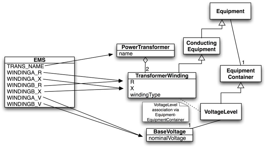
current transformer to be mapped to CIM classes.3.3.2 Representing Power Transformers as CIM Objects
A power transformer is not mapped to a single CIM class, instead it is split down into a
number of components with a single PowerTransformer container class. Thus a two-
winding power transformer becomes two TransformerWinding objects within a
PowerTransformer container. If a tap changer is present to control one of the windings
then an instance of the TapChanger class is associated with that particular winding
while still being contained within the PowerTransformer instance. The UML class
diagram for the classes that form a transformer is shown in Figure 3.11 below.
Figure 3.11 Transformer Class Diagram
Although a PowerTransformer is still a piece of Equipment in the system, it does not
conduct electricity itself and thus does not inherit from ConductingEquipment but from
its parent, Equipment. A TransformerWinding, however, does inherit from
ConductingEquipment since it is physically connected to the network and does conduct
electricity. The TapChanger is part of the TransformerWinding and as such cannot be
considered to be a separate piece of equipment in its own right and inherits from
PowerSystemResource.
The PowerTransformer and TransformerWinding classes have an aggregation
relationship1, meaning that a PowerTransformer is made up on 1 or more
TransformerWindings which in turn can be made up of zero or more TapChangers.
When considering a physical transformer sitting in a substation the PowerTransformer
container can be thought of as the shell of the transformer. The shell itself does not
conduct any of the electricity in the network, but instead holds the windings of the
transformer, the insulating material, magnetic core, and all the other components that
make up the transformer.
1
Although it could be argued that this relationship is composition rather than aggregation the CIM class structure contains no
composition relationships. This is due to the flexible design of the standard, where a composition relationship would indicate a
tighter relationship between classes than is necessary for a number of applications of the standard.The connections from the transformer to the network are made with the windings
themselves, a relationship that is mirrored in the CIM representation where it is the
TransformerWinding class that inherits from ConductingEquipment.
Figure 3.12 CIM Mappings for Transformer 17-33
Thus, Transformer 17-33 from Figure 3.9 can be represented as 4 CIM objects: two
TransformerWindings, one TapChanger and one PowerTransformer as shown in Figure
3.12.
Similarly, a transformer with a tertiary or quartiary winding can be represented as a
single PowerTransformer containing three or four instances of the TransformerWinding
class.
3.3.3 Representing a Current Transformer as a CIM Object
The current transformer CT 17kV does not map directly to a piece of conducting
equipment in the CIM hierarchy as would be expected. The current transformer’s
purpose is to measure the current at its location in the network, and as such when
modelling the network it is the measurement from that location that is modelled rather
than the piece of equipment doing the measuring.
This involves creating an instance of the Measurement class to measure the current at a
particular terminal. As described in Section 3.2.3, each piece of conducting equipment
has one or more terminals to represent the points at which it connects to the network. By
associating a Measurement object with a particular terminal and defining the
measurement taken by that instance to be current then the Measurement object will
reflect the role played by the current transformer.
3.3.4 Defining Containment
As well as having component interconnections defined using the
ConductingEquipment-Terminal-ConnectivityNode associations, the CIM has an
EquipmentContainer class that provides a means of grouping pieces of Equipment
together to represent both electrical and non-electrical containment.
Voltage Levels
Pieces of conducting equipment do not have a voltage attribute to define the voltage as a
specific value, instead they are associated with a VoltageLevel, a subclass of
EquipmentContainer. Each instance of the VoltageLevel class itself has an associatedBaseVoltage object that contains a single attribute to define the nominal voltage of that particular group of components. A BaseVoltage instance may be associated with more than one VoltageLevel, since standard voltage levels (e.g. 33, 132, 275, 400kV) will exist throughout the network. Each VoltageLevel instance, however, contains only the interconnected pieces of equipment at the same voltage level. This is an example of using a subclass of EquipmentContainer to represent electrical containment. Substations The Substation class is a subclass of EquipmentContainer that can contain multiple VoltageLevels and is used to define a collection of equipment “through which electric energy in bulk is passed for the purposes of switching or modifying its characteristics”[1]. In the example network shown in Figure 3.9, the three different voltage levels identified by the dashed bounding boxes are mapped to three instances of the VoltageLevel and contained within a single SubStation instance. Each VoltageLevel object also has an associated BaseVoltage object with a nominal voltage of 17, 33 and 132kV. The Substation class, being a subclass of EquipmentContainer can also contain other instances of Equipment, such as PowerTransformer, which, as previously explained, is itself a container, not a piece of conducting equipment. The Substation class is an example of a subclass of EquipmentContainer to represent non-electrical containment since it will contain pieces of equipment that are physically grouped, but not necessarily electrically connected. Lines The ACLineSegment, however, is not contained within a VoltageLevel, instead it is contained within an instance of the Line class. The Line class in CIM is used to define a “component part of a system extending between adjacent substations or from a substation to an adjacent interconnection point”[1]. A Line may contain multiple line segments of either the AC or DC variety, but does not itself represent a piece of physical conducting equipment. Since a line segment is used to represent “a wire or combination of wires … used to carry alternating [or direct] current between points in the power system”[1] it would be inaccurate to define it as being inside a specific voltage level within a substation. As such, the AC and DCLineSegment classes contain a direct association to the BaseVoltage class to define their nominal voltage level.
3.3.5 Equivalent CIM Representation

     Figure 3.13 Example Circuit with full CIM Mappings
When fully converted to CIM objects, the original example circuit shown in Figure 3.9 is
translated into the 45 CIM Objects shown in Figure 3.13. The BusbarSection’s position
may at first seem erroneous, but in the CIM the ConnectivityNodes are used to define
the point of interconnection for pieces of equipment. As such, the BusbarSection object is
used primarily to provide a point of association (via its terminal) for measurement
objects measuring the voltage at that particular busbar in the system. This reflects the
positioning of equipment in the physical system, since a voltage transformer will often
measure voltages at the busbars within a substation.
This representation of the example network could be extended further with the addition
of objects to represent control areas, equipment owners, measurement units and
generation and load curves, but for now it is enough to understand how an existing
network representation can be mapped to CIM objects.

3.4 IEC 61970-301 CIM Packages
As with any other complex class structure, classes in CIM are grouped together into
packages dependent on their role within the power system. The core IEC 61970-301
standard contains eight main packages, and a global domain package used for defining
data types. The Core, Wires and Topology packages contain all the basic classes for defining the physical characteristics of a power network and, with the exception of the Measurement class, all the classes used in the CIM representation of the example circuit in Section 3.3 come from these three packages. The Wires package defines classes that are required to represent the electrical components of a network, such as Transformers, Lines and Switches, while the Core and Topology packages define the interconnection of components: The Connectivity Node (contained in the Topology package) and Terminal (contained in the Core package). These three packages alone, however, do not fully describe a functioning power system, but provide only the basic electrical characteristics of the equipment and describe how they are connected. To provide a detailed description of a network at an operational level, other classes are required to define the operation and additional characteristics of the equipment, both electrical and non-electrical. The CIM is not only used for exchanging full power system models, as will be covered in more detail later on, the CIM is also used as a common model for defined business process messages. As such, a number of the packages contain classes that are used for business processes and not for defining the properties of a full power system model in CIM format. 3.4.1 Core The Core package contains the parent PowerSystemResource class, from which all other classes concerned with the physical properties of the network inherit (including all classes relating to physical pieces of equipment, as well as Equipment Containers which are used for organising pieces of equipment into groups, such as specific VoltageLevels, or equipment contained within a specific Substation). 3.4.2 Wires The Wires package defines all pieces of equipment electrically connected to the network, as well as supporting classes for defining additional properties and arrangement of objects. This includes classes for the components that are physically connected to the network at the points of power generation and consumption (Energy Consumer and Synchronous Machine, as previously mentioned), as well as several classes that detail the arrangement and settings for Power Transformers, properties for Lines (comprised of one or more Line Segments), and other pieces of conducting equipment including Switches, Busbar Sections and Regulating Conducting Equipment (Compensators). 3.4.3 Generation The Generation package is split into two sub-packages, Production and GenerationDynamics. Production The Production package is used for defining various kinds of generators, and includes a class hierarchy for defining the components of Thermal and Hydro generators. The package also includes definitions of production costing information such as Cost Curves and Net to Gross curves. To define power generation unit in the CIM requires an
association of a production class object with a SynchronousMachine, a class contained
within the Wires package.

GenerationDynamics
The GenerationDynamics package contains the description of Prime Movers, including
turbine types, and classes that define various types of steam supplies, such as
Pressurised or Boiling Water Reactors for nuclear power stations, and different types of
Fossil Fuel Boilers for coal oil and gas fired boilers.

3.4.4 LoadModel
 The LoadModel package deals with modelling energy consumers through curves and
associated data. The EnergyConsumer class (and its subclasses) within the Wires
package define the physical connection point between the network and customer.
Instances of the EnergyConsumer class also contain associations to Load Demand
Models and Schedules for non-conforming load (e.g. large industrial loads, or power
station services).

3.4.5 Topology
The Topology package, together with the Terminal class, provides definitions of how
equipment connects together in the form of Connectivity Nodes. The Topological Node
class is comprised of Connectivity Nodes connected by closed switches (and for many
applications can be considered analogous to a bus in a bus-branch representation). The
Topological Island class contains all electrically connected Topological Nodes, and as
such a fully interconnected power network should contain only one Topological Island.

3.4.6 Measurement
The Meas (Measurement) package is used to define the Measurements being taken from
a particular Power System Resource. There are two ways of connecting Measurements:
 The first option is to associate a measurement instance with a Power System Resource,
which covers measurements not related to electrical connectivity including temperature
or weight.
The second option, as described in Section 3.3.3 is to associate the Measurement with a
Terminal. This is used for measurements dependent on connectivity, such as current or
voltage where the Terminal defines the point of the network that the measurement is to
be taken from. The Measurement class acts as a Current or Voltage Transformer for
measuring the current or voltage at a point in the network, however it does not
represent a piece of physical equipment.

3.4.7 Outage
The Outage package define schedules for the planned network configuration, and
includes classes that associate with a Switch to define its state at a particular time. This is
used primarily for defining business process messages, however it could be used to
change network configurations at specific times during a simulation.
3.4.8 Protection
The Protection package defines the settings and parameters of pieces of protection
equipment that operate Switches. The classes defined in this package are used to
describe the behaviour of the Switch: its current limit, delay from detection of abnormal
conditions to operation, maximum and minimum limits.
4 The eXtensible Markup Language (XML)

4.1 XML
XML, the eXtensible Markup Language, is a “universal format for structured documents
and data”[3], which is quickly becoming the standard for storing machine-readable data
in a structured, extensible format that is accessible over the internet. XML is actually a
meta-language2 that allows the user to design their own markup language to describe
the structure of the data.
XML is a subset of SGML, the Standard Generalized Markup Language[6] designed for
both on and offline storage and transferral of data. The data is encoded as plain text,
thus allowing it to be both human and machine-readable and the use of standard
encoding schemes makes it platform independent.
The XML syntax uses tags to denote the elements within the document. Each element is
either expressed as an open and close tag containing data of the form:
...Contained Data...
Or with as a single empty entry closed with a slash at the very end:

An entry may also contain its own attributes which are expressed in the form:
 or
...
When an element has a start and end tag, any other elements contained within these two
tags are classed as “children” of the parent element.

4.1.1 Simple XML Example
As an example, a simple XML tag-syntax to store a book can be created. The contents
and properties of the book can then be expressed as XML, using self-descriptive tags of
the form:

     2006
     January
     1

     Welcome to this book…
     …
     …
     …and we shall continue

 2
     A meta-language is a language used to describe a language (whether it be another language or itself).
To understand the uses…
…
Here the book element contains its own attribute to describe the title and author, with a
child element to describe the revision of the book, plus several chapter elements. The
chapters in turn contain elements for each paragraph, which themselves contain mixed
data of other elements and text. Although to anybody with knowledge of the English
language, the names of these tags make their semantics clear, the tag syntax and
semantics must still be clearly defined if the data is to be interpreted correctly by an
application.
4.1.2 XML Schema
While XML itself has no set tag-syntax or semantics, schemas can be defined for
expressing almost any kind of data using XML notation. An application interpreting
XML data must be given this knowledge of the syntax and semantics used, otherwise it
will have trouble interpreting it. This requires the tag-syntax and semantics of the XML
to be expressed as a schema, which provides constraints on the structure and contents of
an XML document.
The most common formats for describing these schemas are in Document Type
Definition (DTD)[4] format or the newer XML Schema[5]. The XML Schema defines the
elements and attributes that can appear in a document; which elements are child
elements; the number of allowed child elements for each element type; whether an
element can include text (i.e. is an empty element or within an open and close tags); the
data types for elements and attributes; whether their values are fixed; and if they have
default values.
Using the previous book example, a simple XML Schema can be created to describe the
elements within the document and the restrictions placed on them. This example
schema is shown, along with additional comments, in Figure 4.1Figure 4.1 Annotated simple XML Schema Example describing the data within a book
The other notable feature of this document is the introduction of namespaces. In the
example above, every element is prefixed by xs:. The document’s root node contains an
xmlns:xs=”http://www.w3.org/2001/XMLSchema” attribute which indicates that every
element prefixed with xs is an XML element that is part of the namespace identified by
the Unique Resource Identifier (URI) http://www.w3.org/2001/XMLSchema3. An XML
document can contain elements from multiple namespaces simultaneously, each of
which denote a seperate XML Schema with its own set of restrictions. For the previous
example, the root node could become:
Indicating that the XML document may contain elements from the
http://www.other.com/2005/ABSchema namespace, identified by an ab prefix, along
with elements from http://www.something.com/2004/YZ-Schema namespace,
identified by a yz prefix in addition to the original
http://www.w3.org/2001/XMLSchema namespace.
3
The W3C is the World Wide Web Consortium, the governing body for web standards. Their domain is w3.org and as such W3C
standards such as XML Schema and RDF use this domain as part of their unique resource identifier.4.2 RDF With a basic XML document there is no way to denote a link between two elements that are not parent or child. For instance, consider a library system containing entries for multiple books with information on their shelf position in the form: Each book element is contained within the library as an independent entry, but should the user wish to add a link between the History of Glasgow, 1900-1950 and History of Glasgow, 1950-2000 books to indicate that reader may wish to read the former book before the latter, there is no standard way to do this using the basic XML constructs. The Resource Document Framework (RDF)[9] is an XML schema used to provide a framework for data in an XML format by allowing relationships to be defined between XML nodes. Each element can be assigned a unique ID attribute under the RDF namespace http://www.w3.org/1999/02/22-rdf-syntax-ns# (which uses the rdf prefix). Adding a resource attribute to an element allows references to be made between elements by having its value refer to another element’s ID. 4.2.1 Simple RDF Example For the library example above, assigning an ID under the RDF namespace to each book allows the addition of sequel and sequelTo elements. These elements contain only a single resource attribute that point to another element within the document by referencing their ID. To distinguish between the library elements and attributes, themselves governed by an XML Schema, and the RDF elements and attributes, an additional namespace http://www.strath.ac.uk/libraries/2006/library-schema# is added with the prefix lib. An RDF root element is also added with xmlns attributes to denote the namespaces and prefixes. The new Library RDF XML representation is shown below:
As shown, the RDF provides a means of showing relationships between elements
outwith the standard parent-child relationship. The schema contains additional
elements that go beyond the simple ID and resource attribute as will be shown in next
section, but it is these features of the framework that are utilised when expressing the
CIM in XML format.

4.2.2 RDF Schema
While RDF provides a means of expressing simple statements about the relationship
between resources, it does not define the vocabulary of these statements. The RDF
Vocabulary Description Language, known as RDF Schema[10] provides the user with a
means of describing specific kinds of resources or classes. The RDF Schema does not
provide a vocabulary for a specific application's classes like lib:sequel or lib:sequelTo, or
properties like lib:title and lib:author. Instead, the RDF Schema allows the user to
describe these classes and properties themselves and indicate when they should be used
together. For example, they may state that the property lib:title will be used in
describing a lib:book, or that lib:sequel is an element of lib:book and should indicate a
reference to another lib:book entry.
In essence, the RDF Schema provides a type system for RDF. The RDF Schema type
system is similar to that of object-oriented programming languages such as Java, .NET
and C++. Amongst other things, RDF Schema allows resources to be defined as
instances of one or more classes and for these classes to be organised in a hierarchy.
For the previous example, the RDF Schema would, amongst others, contain entries to
describe the class book and the properties sequel and sequelTo.
Indicates that the book is the sequel to another book also
within the library

Here, the class of book is defined, then the two properties sequel and sequelTo are defined.
Each of these properties has their domain (the class the property is within) referencing
the book class, as does their range (the class of element the property refers to). Should
the library schema be extended so that instead of just having a book element, fictional
novels could be differentiated with a separate novel element that, when modelled in
UML, would be a simple sub-class of the existing book class. This can be represented in
RDF Schema as:
TransformerWinding

  TapChanger

  MemberOf_PowerTransformer

  TransformerWinding

Each CIM Class has a corresponding rdfs:Class entry, while the two aggregation
relationships are expressed as RDF Property elements with the appropriate domains and
ranges. The entire CIM Class structure can be expressed in this manner, and then this
RDF Schema can be used to express a CIM power system model as RDF XML.

4.3.1 CIM RDF XML Example
As an example, the simple Transformer example from Figure 3.12 will be extended to
include attributes for each object. This produces four objects with their own internal
data as shown in Figure 4.2 below:
Figure 4.2 Transformer shown as four CIM Objects with attributes
Each of these objects can then be expressed as an XML node using the CIM RDF Schema
given the namespace http://iec.ch/TC57/2003/CIM-schema-cim10# and prefix cim:

  17-33

  0
  0.099187
  115.00

  4.701487

  PrimaryWindingOf_17-33
0
  0.39675
  230.00

  18.80595

  SecondaryWindingOf_17-33

  20
  -20
  115.00
  0
  0
  0.641

  TapChangerOf_PowerTransformer_17-33

The PowerTransformer.transformerType and TapChanger.tculControlMode elements
do not refer to other nodes within the document; instead their values are of an
enumerated type. Enumerated types consist of a fixed set of legal values (e.g. for a
variable of type Days, the enumerated type would be: Sunday, Monday, Tuesday,
Wednesday, Thursday, Friday, Saturday and any variable of this type must have one of
these values). Within the CIM there are certain class attributes that are also enumerated
types and do not contain a node value but instead refer to an enumerated type within its
RDF Schema.
This combination of the CIM, XML, RDF and RDF Schema allows an entire CIM power
system model to be expressed in a standard, cross-platform plain-text format that is both
human and machine readable and extensible.

5 XML Messaging
As well as exchanging full power system model data as CIM RDF XML, the other main
application of the CIM is as a common semantic model for enterprise application
integration.
5.1 Existing Inter-Application Communication Infrastructure
Within large companies there will be a number of computer applications that must
communicate with each other. This often results in a large number of point-to-point
links using custom formats and protocols to exchange data between software
applications from a number of vendors. Adding a new application to the system
requires additional communication links to be defined and implemented, further
increasing the complexity of the overall system with a corresponding financial penalty.

     Figure 5.1 Communication links between enterprise applications
As illustrated in Figure 5.1, even for a small section of the overall IT system, this can
result in a large number of inter-application communication links. As companies expand
their IT infrastructure or replace existing applications with products from other vendors
they must define new interfaces for each communication link, a process that is both time
consuming and expensive.

     Figure 5.2 Enterprise Application Bus model for inter-application communication
You can also read