High Effi ciency Nuclear Power Plants Using Liquid Fluoride Thorium Reactor Technology
←
→
Page content transcription
If your browser does not render page correctly, please read the page content below
NASA/TM—2009-215829                           AIAA–2009–4565

High Efficiency Nuclear Power Plants Using
Liquid Fluoride Thorium Reactor Technology
Albert J. Juhasz
Glenn Research Center, Cleveland, Ohio

Richard A. Rarick and Rajmohan Rangarajan
Cleveland State University, Cleveland, Ohio

October 2009
NASA STI Program . . . in Profile

Since its founding, NASA has been dedicated to the            •   CONFERENCE PUBLICATION. Collected
advancement of aeronautics and space science. The                 papers from scientific and technical
NASA Scientific and Technical Information (STI)                   conferences, symposia, seminars, or other
program plays a key part in helping NASA maintain                 meetings sponsored or cosponsored by NASA.
this important role.
                                                              •   SPECIAL PUBLICATION. Scientific,
The NASA STI Program operates under the auspices                  technical, or historical information from
of the Agency Chief Information Officer. It collects,             NASA programs, projects, and missions, often
organizes, provides for archiving, and disseminates               concerned with subjects having substantial
NASA’s STI. The NASA STI program provides access                  public interest.
to the NASA Aeronautics and Space Database and
its public interface, the NASA Technical Reports              •   TECHNICAL TRANSLATION. English-
Server, thus providing one of the largest collections             language translations of foreign scientific and
of aeronautical and space science STI in the world.               technical material pertinent to NASA’s mission.
Results are published in both non-NASA channels
and by NASA in the NASA STI Report Series, which              Specialized services also include creating custom
includes the following report types:                          thesauri, building customized databases, organizing
                                                              and publishing research results.
•   TECHNICAL PUBLICATION. Reports of
    completed research or a major significant phase           For more information about the NASA STI
    of research that present the results of NASA              program, see the following:
    programs and include extensive data or theoretical
    analysis. Includes compilations of significant            •   Access the NASA STI program home page at
    scientific and technical data and information                 http://www.sti.nasa.gov
    deemed to be of continuing reference value.
    NASA counterpart of peer-reviewed formal                  •   E-mail your question via the Internet to help@
    professional papers but has less stringent                    sti.nasa.gov
    limitations on manuscript length and extent of
    graphic presentations.                                    •   Fax your question to the NASA STI Help Desk
                                                                  at 443–757–5803
•   TECHNICAL MEMORANDUM. Scientific
    and technical findings that are preliminary or            •   Telephone the NASA STI Help Desk at
    of specialized interest, e.g., quick release                  443–757–5802
    reports, working papers, and bibliographies that
    contain minimal annotation. Does not contain              •   Write to:
    extensive analysis.                                           NASA Center for AeroSpace Information (CASI)
                                                                  7115 Standard Drive
•   CONTRACTOR REPORT. Scientific and                             Hanover, MD 21076–1320
    technical findings by NASA-sponsored
    contractors and grantees.
NASA/TM—2009-215829 AIAA–2009–4565 High Efficiency Nuclear Power Plants Using Liquid Fluoride Thorium Reactor Technology Albert J. Juhasz Glenn Research Center, Cleveland, Ohio Richard A. Rarick and Rajmohan Rangarajan Cleveland State University, Cleveland, Ohio Prepared for the Seventh International Energy Conversion Engineering Conference (IECEC) sponsored by the American Institute of Aeronautics and Astronautics Denver, Colorado, August 2–5, 2009 National Aeronautics and Space Administration Glenn Research Center Cleveland, Ohio 44135 October 2009
Acknowledgments

                             This work was conducted at NASA Glenn Research Center’s
                       Thermal Energy Conversion Branch and Cleveland State University (CSU).

                                         This report is a formal draft or working
                                         paper, intended to solicit comments and
                                           ideas from a technical peer group.

                                        This report contains preliminary findings,
                                         subject to revision as analysis proceeds.

                           Trade names and trademarks are used in this report for identification
                              only. Their usage does not constitute an official endorsement,
                              either expressed or implied, by the National Aeronautics and
                                                 Space Administration.

                 Level of Review: This material has been technically reviewed by technical management.

                                                     Available from
NASA Center for Aerospace Information                                                 National Technical Information Service
7115 Standard Drive                                                                                   5285 Port Royal Road
Hanover, MD 21076–1320                                                                                Springfield, VA 22161

                                   Available electronically at http://gltrs.grc.nasa.gov
High Efficiency Nuclear Power Plants Using
Liquid Fluoride Thorium Reactor Technology
Albert J. Juhasz
National Aeronautics and Space Administration
Glenn Research Center
Cleveland, Ohio 44135
Richard A. Rarick and Rajmohan Rangarajan
Cleveland State University
Cleveland, Ohio 44115
Abstract
An overall system analysis approach is used to propose potential conceptual designs of advanced
terrestrial nuclear power plants based on Oak Ridge National Laboratory (ORNL) Molten Salt Reactor
(MSR) experience and utilizing Closed Cycle Gas Turbine (CCGT) thermal-to-electric energy conversion
technology. In particular conceptual designs for an advanced 1 GWe power plant with turbine reheat and
compressor intercooling at a 950 K turbine inlet temperature (TIT), as well as near term 100 MWe
demonstration plants with TITs of 950 and 1200 K are presented. Power plant performance data were
obtained for TITs ranging from 650 to 1300 K by use of a Closed Brayton Cycle (CBC) systems code
which considered the interaction between major sub-systems, including the Liquid Fluoride Thorium
Reactor (LFTR), heat source and heat sink heat exchangers, turbo-generator machinery, and an electric
power generation and transmission system. Optional off-shore submarine installation of the power plant is
a major consideration.
Introduction
In meeting the increasing demand for electrical energy today’s global economies are faced with the
dual problem of declining fossil fuel resources (Hubbert 1956) and climate change due to atmospheric
accumulation of “greenhouse gases,” principally CO2 and methane. An obvious solution to both issues
would be a power generation process that does not require fossil fuels and also does not have any gas
emissions. Among the proposed near term “alternative energy” sources, the reliability and capacity factor
of traditional nuclear fission power plants has steadily improved over the years to a level of ~ 92 percent,
which is more than twice that of “solar” or “wind”. Additional benefits from nuclear power are possible,
if investment in “nontraditional” nuclear power generation is undertaken. The inherent advantages of such
advanced power generation schemes were recognized by the United States Congress when it passed the
“Energy Policy Act of 2005” (U.S. 109th Congress, 2005). Development of advanced nuclear power
plants was advocated under “Title VI—Nuclear Matters” and the goals of the “Generation IV Nuclear
Energy Systems Initiative” were spelled out under Subtitle C “Next Generation Nuclear Plant Project”
(NGNPP). In essence, these goals were to generate electric power for base load energy demands and to
produce hydrogen as a new carbon free fuel for vehicular transportation. Furthermore, Generation IV
(Gen IV) power plants were to be highly economical, equipped with safety enhancements, have minimal
waste, and be proliferation resistant. To meet these objectives a number of “closed cycle gas turbine”
(CCGT) energy conversion systems either directly coupled to high temperature gas (cooled) reactors
(HTGR), (Richards et al., 2005), or indirectly coupled via intermediate heat exchangers (IHX) to liquid
cooled reactors have been proposed. For both configurations the gas turbine working fluid is helium (He),
with power plant output ranging from tens of megawatts (MW) to gigawatt (GW) levels.
NASA/TM—2009-215829 1Figure 1—Energy conversion cycle comparisons.
A good comparison of the performance of power plants using either gas turbine (Brayton), or steam
turbine (Rankine) energy conversion systems, in terms of the thermodynamic plant efficiency is shown in
Figure 1, which was adapted from the literature (LaBar 2002), except for the abscissa coordinates altered
from “F” to “K”. Due to the higher cycle temperature ratios enabled by the higher turbine inlet
temperatures for gas turbine systems, a 50 percent increase in CCGT plant efficiency can be realized,
when compared to the highest efficiency achievable with the steam cycle. Hence most Gen IV energy
conversion systems are based on the CCGT power cycle, also referred to as the Closed Brayton Cycle
(CBC). For optimum rotor-dynamic performance vertical orientation of the compressor- turbo-alternator
machinery has been proposed (Zhao and Peterson 2005, Kodochigov 2008). Acronyms like High
Temperature Gas Reactor (HTGR) or Gas Turbine Modular Helium Reactor (GT-MHR) (Baxi, 2006,
2009) refer to the directly CBC systems, while CBC energy conversion via the Very High Temperature
Reactor (VHTR), MSR(Molten Salt Reactor), or LFTR (Liquid Fluoride Thorium Reactor) refer to
indirectly heated cycles. Note that, due to the much higher heat transfer capability of liquid (molten) salt
or metal, a VHTR can operate at higher outlet temperatures than the HTGR. The drawback is that
additional investment in liquid-to-gas heat exchangers and circulating pumps must be made. However,
such investment may be warranted if one considers that for a 1000 MWe plant generating power at
5 c/KW-hr ($50/MW-hr) each percent increase in plant efficiency translates into nearly $4.5 M in
additional revenue.
Hence the objective of this paper is to examine how gas turbine power systems could use fission
reactor heat sources based on the LFTR technology, developed at ORNL (Engel, 1980) during the
“Molten Salt Reactor Experiment” (MSRE) program.
The Thorium Fuel Cycle and LFTR Power Plant
The Thorium fuel cycle is based on a series of neutron absorption and beta decay processes initiated
by neutron absorption and beta decay reactions starting with naturally occurring thorium-232 as the fertile
material and the artificial uranium-233 (92 U233) isotope as the fissile reactor fuel. Table I shows the three
essential nuclear reactions (Glasstone and Sesonske, 1967):
NASA/TM—2009-215829 2TABLE I.—THORIUM—URANIUM BREEDING CYCLE
232
1. 90Th + 0n1 Æ 90Th233 + γ (neutron absorption)
233
2. 90Th Æ -–1β0 + 91Pa233 (β decay – λ = 22.3 min)
233
3. 91Pa Æ – 1β0 + 92 U 233 (β decay – λ = 27 days)
The nuclear reaction indicated by “step 1” shows, that a neutron absorbed by thorium-232 will bring
about a transmutation to a new isotope, namely thorium-233 and emission of a gamma photon. Note that a
logical source for the neutron required for absorption is a power producing fission reactor with the fertile
thorium-232 contained in an annulus or blanket enveloping the reactor core. The thorium-233 isotope
next (step 2) emits an electron (beta decay) as it rapidly transmutes to protactinium-233. With a half life
of only 22.3 min over 99.9 percent of the 90Th233 is converted into 91Pa233 in 4 hr. In step 3 the
protactinium-233 isotope itself undergoes a slow transmutation process by beta decay, with a half life of
27 days, there is a storage requirement or about 10 months for the protactinium-233 to decay to the fissile
uranium-233.
Molten Salt Reactor Technology
The originators of this ‘fluid fuel reactor’ technology were nuclear researches at ORNL, under the
direction of Alvin Weinberg who served as director of ORNL from 1955 to 1973. The motivation for and
the intended first application was in support of the Nuclear Aircraft project in the late 1940s under the
‘Homogeneous Reactor Experiment” (HRE) and the ‘Aircraft Nuclear Propulsion (ANP) project. Reactor
outlet temperatures near 1100 K (820 °C) were achieved before the program was discontinued in 1961.
However the technology acquired was shifted to a ground based civilian version of a “meltdown proof”
reactor, serving as heat source for both a steam power plant and later for a CBC (Engel et al., 1980).
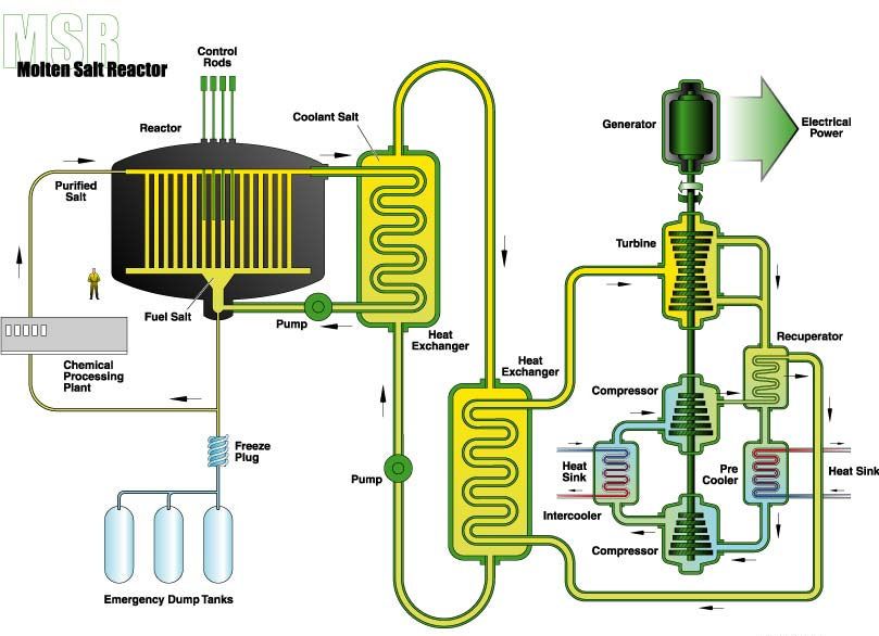
A schematic diagram of the ORNL-MSR Gas turbine power plant is displayed in Figure 2. Shown on
the left side of the figure is a graphite matrix moderated MSR reactor with fuel salt mixture (ThF4-U233F4)
being circulated by a pump through the core and to a primary (shell-tube) heat exchanger. Note that a
parallel loop permits part of the fuel salt to be diverted to a processing plant and reintroduced into the
core as ‘purified salt’. - As one of the unique safety features, a melt-plug at the reactor bottom would
permit the reactor fluid fuel to be drained into subcritical dump tanks, located in a underground storage
facility, should the fuel salt temperature exceed a preset limit. A second pump circulates the liquid heat
transfer fluid (LiF-BeF2) through an intermediary heat exchanger where the helium working fluid is
heated to turbine inlet temperature. The high pressure-high temperature He is shown to flow through two
parallel turbines which drive two intercooled series compressors and the electric power generator, all
mounted on the same shaft. The turbine exhaust flows pass through the hot side of a recuperator where
thermal energy is transferred to the high pressure compressor discharge flow before entering the water
cooled heat sink heat exchanger (HSHX) which lowers the working fluid temperature to the value
required by the LPC (low pressure compressor) inlet condition. The compressor raises both pressure and
temperature of the He working fluid before the fluid is cooled back to near inlet temperature by the
intercooling He-water heat exchanger. Due to the lower temperature at the inlet of the HPC (high pressure
compressor), the compressor work will be reduced significantly, thus allowing more shaft power for the
generator and thereby leading to higher plant efficiency. As a final step in completing the circuit, the He
working fluid exiting the high pressure compressor enters the cold side of the recuperator where it is
preheated by the turbine exhaust stream. The helium then enters the secondary heat exchanger where it is
heated to the turbine inlet temperature requirement as explained above.
Although not shown in the schematic, reactor core heat can also be used for H2 production by
processes like high temperature electrolysis of water, or the water gas shift reaction. Thus all of the
objectives set forth under the Energy Policy Act of 2005 could be accomplished with advanced nuclear
technology as represented by MSR or LFTR.
NASA/TM—2009-215829 3Gen-4 Liquid 2 Salt Configuration
LiF-BeF2 Reactor Concept –
He
ThF4 – UF4
LiF-BeF2
#1
#2 He
2
Figure 2.—ORNL’s MSR/LFTR Power Plant with CBC conversion.
Technological Advantages of LFTR Power Plants
Compared to traditional nuclear reactors which “burn” the fissile uranium isotope U235 the LFTR uses
fissile U233 which is derived from Th232. But whereas U235 constitutes only 0.7 percent of mined natural
uranium, practically all of the Thorium can be converted to U233, and no processing for enrichment is
needed. As will be shown in a later section of this paper, at turbine inlet temperatures of 1200 K closed
cycle gas turbine thermal energy conversion efficiency, ηt, of over 50 percent can be attained, as
compared to a 30 to 35 percent efficiency for currently operating steam turbines plants with inlet
temperatures of approximately 570 K (300 °C). Thus a factor of three hundred times as much output
electric power per unit mass of raw fuel ore (uranium oxide (U3O8) versus Thoria (ThO2) can be obtained
via the Thorium fuel cycle with closed cycle gas turbine energy conversion. As a result fission fragment
waste products are reduced by a commensurate amount, and their radioactivity would decay to
background levels in less than 300 years, as contrasted to over 10,000 years for currently used reactors,
thus obviating the need for long term storage, such as at Yucca Mountain. The thermal spectrum LFTR
concept is inherently safe, with a negative temperature coefficient of reactivity, thus making a “core
meltdown” due to loss of coolant impossible. Since the fuel is a pumped liquid solution of LiF-BeF2-UF4,
refueling can be accomplished without reactor shutdown. The fissile fuel can also be made “proliferation
resistant” by permitting it to be contaminated (denatured) with small amounts of U232 to increase its dose
rate which would greatly reduce its unshielded exposure time and greatly increase detectability.
With Thorium ores, such as Monazite, being four times more abundant in the earth’s crust than
uranium ores, over 60 percent of the worlds resources are located in the following democratically
NASA/TM—2009-215829 4governed countries: Australia (18 percent), United States (16 percent), India (13 percent), Brazil
(9 percent), and Norway (5 percent). Thus future global energy demands could be met by these Thorium
sources for over several tens of millennia.
Conceptual Design Modeling of Gas Turbine LFTR Nuclear Power Plants
Having established that Closed Cycle Gas turbine power plants with both directly or indirectly
supplied thermal energy from nuclear heat sources would best meet the NGNPP-Gen IV power plant
requirements, an author generated CBC code previously used in the modeling of space and planetary
surface power systems (Juhasz 2005, 2006, 2007) was modified to meet the modeling requirements of
terrestrial nuclear power plants. Special emphasis was placed on incorporating the two series heat
exchanger requirements of LFTR–reactors as exemplified by ORNL MSRE technology.
Furthermore the provision for treating CBC compression and turbine expansion processes as
composed of separate incremental series steps allowed for realistic modeling of power systems with
compressor intercooling and/or turbine reheat options. Since cycle reject heat and intercooling heat
transfer is accomplished via gas-water heat exchangers, the space radiator heat rejection sub-routines
were bypassed in the modeling computations. Allowing for the working fluid passing through heat
exchangers on the cycle hot side, recuperator, compressor intercooler and heat sink, the cycle pressure
drop was set at 4 percent. Thus the turbine overall turbine pressure ratio for up to three series machines
was 96 percent of the overall pressure ratio produced by the compressors. Provision was added to
compute and display local pressure and temperature state points along the system schematic diagrams for
moiling simulations for different cycle configurations, TITs and power output levels.
A list of key input values which were kept constant is shown in Table II.
TABLE II.—KEY CYCLE INPUT PARAMETERS
Compressor Inlet Temperature (TIC), K........................................ 300
Cooling Water Temperature, K...................................................... 288
Reactor Heat Loss, percent ............................................................. 1.0
Polytropic Efficiency—Compressor, percent ................................. 86
Polytropic Efficiency—Turbine, percent ......................................... 92
Recuperator Effectiveness, percent .................................................. 95
Intercooler HX Pressure Loss, percent ........................................... 0.5
Reheat HX Pressure Loss, percent .................................................. 0.8
Turbine Pressure Ratio Fraction, percent ......................................... 96
Generator Efficiency, percent .......................................................... 98
Several conceptual power plant cycle configurations were modeled using the code briefly described
above. As shown in Figure 3, the first of these is for a 1000 MWe power plant with turbine reheat and
compressor intercooling (availability of water cooling reservoirs assumed), with a TIT of 950 K. With
three series turbines and compressors, and the required heat exchangers on the hot side and cold side of
the cycle, a fairly convoluted cycle schematic was analyzed. Note that the total He mass flowrate was
only about 681kg/s for this three series turbomachine configuration with an overall pressure ratio of 8,
with each stage ratio of 2. The specific work parameter of 1468 kJ/kg expresses the ratio of total power
output of 1000 MWe = 106 kJ/s to 680 kg/s. This flowrate is only a third of the over 2100 kg/s that would
have been required for accomplishing the same power output with one large single compressor and
turbine and the resulting specific work for this case would be less than 500 kJ/kg. So the system
complexity is offset somewhat by much smaller rotating machinery and heat exchanger size. However
another drawback is that, due to the cascading pressure levels the turbo-generator speeds (in rpm)
optimize at 7200 for the HPT, 5400 for the MPT and 3600 for the LPT. This would require speed reducer
transmissions for changing the intermediate and high pressure turboset speeds to 3600 rpm, for generation
of 60 Hz electric power via 2 pole alternators.
NASA/TM—2009-215829 5743 K
984 K
1.01 MPa 300 K
950 K 410 K
333 MWe
2.0 MPa 2 MPa
P HS3 LPT Gen 3 LPC IC1
HX HX
P 3600 rpm P
743 K
2.02 MPa 300 K
950 K 410 K
333 MWe
Thorium 4.0 MPa 4 MPa
Reactor
HS2 MPT Gen 2 MPC IC2
2365 MWth HX HX
P 743 K 5400 rpm P
4.04 MPa 300 K
950 K H2O
333 MWe
7.99 MPa 288 K
HS1 HPT Gen 1 HPC
HX
P 7200 rpm
727 K 410 K
7.99 MPa 8 MPa
768 K P
& LiF = 7220 kg / s
m Recuperator SKHX
Specific Work = 1468 kJ / kg 427 K
& He = 681 kg / s
m
Figure 3.—Schematic of 1 GW liquid fluoride thorium reactor power plant with 950 K turbine reheat and compressor
intercooling. Plant efficiency is ~42 percent.
The reactor thermal power is shown to be 2365 MWt, which indicates a pant thermal efficiency of
42.3 percent. Even after subtracting the approximately 3 MWe for combined pump power requirements
the plant efficiency is still above 42 percent for the 950 K TIT, requiring a reactor outlet temperature of
under 990 K, assuming high effectiveness heat exchangers. Of course, just like for the ORNL MSR
system, the primary reactor fuel-coolant is uranium tetra fluoride (U233F4) which may also contain LiF-
BeF2 eutectic in solution. The secondary heat exchanger fluid is LiF-BeF2 liquid salt with a melting point
of ~ 630 K.
The next cycle analyzed, shown in Figure 4, has been greatly simplified by removing the reheat
feature, but keeping the three series intercooled compressors. The TIT is still 950 K, but the output power
level is reduced to 100 MWe. Note that the overall pressure ratio for this system is ~ 2.21 (i.e., 2.08 MPa:
0.94 MPa). Even though there is no ‘reheat’, the total turbine expansion work is split into two sections.
The HPT (high pressure turbine) work is dedicated to driving the three series compressors with
intercooling after the first and the second stage. The output of the low pressure turbine (LPT) at a
TIT—834 K is used to drive the 100 MWe generator. Although the turbine speed still optimized at
7200 rpm, higher power output levels with higher machine diameters would lead to optimum turbine
speeds near 3600 rpm. But to design a 3600 rpm turbo-generator for a 100 MWe output the operating
pressure levels could be reduced, albeit the turbomachine diameters would thereby need increase.
NASA/TM—2009-215829 6834 K
Notation: 1 P = 1 MPa 1.37 P
100 MWe
LPC MPC HPC HPT Gen LPT
950 K 7200 rpm 746 K
340 K 300 K 340 K 300 K 340 K
2.01 P 0.943 P
1.22 P 1.22 P 1.59 P 1.59 P 2.08 P
974 K 997 K
IC1 IC2
HX HX
Thorium
HS2 HS1 Reactor
P P
HX HX
242 MWth
P
H O 288 K
2
730 K
P
P 706 K 754 K
2.05 P
m=480 kg/s
300 K SKHX 359 K Recup
0.94 P m He = 189 kg/s
0.941 P
Specific Work = 529 kJ / kg
Figure 4.—Schematic of 100 MWe liquid fluoride thorium reactor power plant with 950 K turbine (no reheat) and
compressor intercooling. Plant efficiency is ~ 41.3 percent.
Note, that even without reheat the plant thermal efficiency only dropped about one percent.
Compared to Figure 3, the number of hot side heat exchangers has been reduced from four to two. Such
beneficial results with intercooling only were also pointed out in the reference literature (Frutschi, 2005).
Note that the ‘specific work’ parameter has decreased to about 530 kJ/kg. This is indicated by the
relatively high He mass flowrate requirement of 189 kg/s for this 100 MWe power output, when
compared to the 681 kg/s mass flow for the 1000 MWe case of Figure 3. The primary and intermediate
heat exchanger mass flows were computed on the basis of thermal capacity and density of the respective
‘liquid fuel’ (U233F4) and LiF-BeF2 heat transfer fluids.
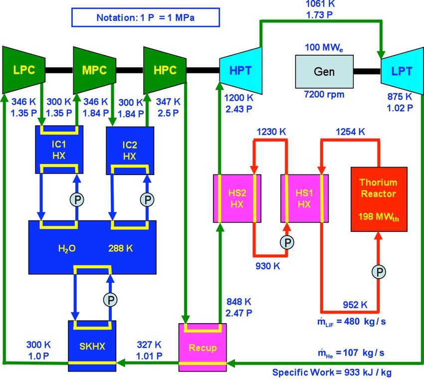
NASA/TM—2009-215829 7Figure 5.—Schematic of 100 MWe liquid fluoride thorium reactor power plant with 1200 K turbine (no
reheat) and compressor intercooling. Plant efficiency is ~ 50.5 percent.
As shown in Figure 5, the last case analyzed was for a 100 MWe power output with the ‘intercool
only’ option. But the TIT was increased to 1200 K, thus providing a cycle temperature ratio of 4. For this
higher temperature ratio the plant thermodynamic efficiency increased to 50.5 percent and the overall
optimum pressure ratio to 2.5. The specific work parameter almost doubled to 933 kJ/kg. This is as also
reflected by the reduced He mass flowrate of 107 kg/s. Note also that the high pressure turbine exit
temperature, which is also the inlet temperature for the low pressure turbine, increased from 834 K for the
case discussed in Figure 4 to 1061 K for this higher TIT.
The higher plant thermal efficiency and specific work values, coupled with lower working fluid mass
flowrate requirement, reinforce the fact that higher peak cycle temperatures enabled by advances in high
temperature materials technology are the key to achieving economies in lower heat input requirements
and lower component sizes. These promising trends augur well for rewards in the future if required
investments are made in the present.
The results of a systematic increase in TIT from 650 K to 1300 K for ‘Intercooled Only’ and
‘Intercooled + Reheated’ gas turbine systems are shown in Figures 6 and 7, respectively. The first case,
illustrated by the red curves, represents configuration of three series compressors and a single turbine.
NASA/TM—2009-215829 8100 MWe – 3 Compressor Closed-Loop Brayton Cycle
55
50
Plant Efficiency ( % ) 45
40
35
30
25
1 Turbine
3 Turbine
20
600 700 800 900 1000 1100 1200 1300
Temperature ( K )
Figure 6.—Power plant efficiency as a function of turbine inlet temperature
for only intercooled (one turbine) and intercooled + reheated (three
turbines)—100 MWe CCGT power plant.
100 MWe – 3 Compressor Closed-Loop Brayton Cycle
700
1 Turbine
3 Turbine
600
He Mass Flow Rate ( kg / s )
500
400
300
200
100
0
600 700 800 900 1000 1100 1200 1300
Temperature ( K )
Figure 7.—Power plant mass flowrate as a function of turbine inlet temperature
for only intercooled (one turbine) and intercooled + reheated (three
turbines)—100 MWe CCGT power plant.
NASA/TM—2009-215829 9The second case, illustrated by the blue curves, is representative of the three reheated series turbines
plus three series intercooled compressor case, as shown in Figure 3. The dramatic increase in power plant
thermal efficiency from the low 20’s percent range for a TIT of 650 K, to over 53 percent at a TIT of
1300 K is shown in Figure 6. For the change in turbine inlet temperature shown the optimum pressure
ratios increase from about 1.8 to 2.5 for the ‘Intercool only’ case. But for the ‘Intercool + Reheat’ case
the optimum pressure ratios increase from about 2.8 to near 8.0 over the same temperature range. Due to
the higher pressure ratios, the isentropic compressor efficiencies are lower for the same polytropic value
of 86 percent as shown in Table II. This explains why the efficiency values for the ‘Intercooled only’
configuration surpass those for the ‘Intercool + Reheat’ at the high turbine inlet temperatures. But,
regarding total helium mass flowrate, Figure 7 shows that while the mass flow decreases by a factor of
~ 6 over the temperature range, the three turbine ‘Intercool + Reheat’ configuration requires less than half
the mass flow of the ‘Intercool only’ option. Since turbo-machine and heat exchanger size at the same
operating pressure is proportional to working fluid mass flow, having larger sized components is the cost
for reduction in system complexity offered by the single turbine ‘Intercool only’ option.
Plant Sub-Marine Basing and High Voltage dc Power
Although proposed here only in conceptual form with detailed designs to be generated at some future
time, an LFTR-CBC power plant could be based off shore in a large submarine pressure vessel and the
three phase ac power generated could be transformed to high voltage before rectification-conversion to
HVDC and transmission via submarine cables to users in coastal regions. A preliminary electrical wiring
scheme for power output from two parallel turbo-generators is shown in Figure 8.
The generator employed for the conversion process is an ac synchronous generator. The generated ac
voltage is converted into dc voltage using a rectifier. A converter transformer is employed to step up the
generated voltage to the necessary transmission voltage level. The converter transformer has two
secondary windings, a delta and a Y-winding. This construction facilitates a 12-pulse rectification in the
Figure 8.—Possible wiring for HVDC power transmission between source and load.
NASA/TM—2009-215829 10rectifiers. The construction of the converter transformer also suppresses the fifth and the seventh
harmonic in the system. The dc voltage output from the ac-dc rectifier has very low ripple and hence low
losses. Smoothing reactors are employed to reduce ripples from the system in conjunction with dc The
layout of a HVDC transmission system is shown in figure below. The mechanical energy filters. This
improves the power quality of the transmitted power. The smoothing reactor, dc filter also act as
protective devices and reduce the current surges in the system, in case of a fault. The smooth, filtered dc
voltage is transmitted via submarine HVDC transmission cable. The transmitted dc has to be converted
back to ac voltage for transmission and distribution purposes. The dc is converted into ac by employing a
low loss, high efficiency multilevel converter. The inverted voltage is stepped up or down depending on
the voltage on the terrestrial grid. The layout shows the other protective devices in the system. Some
obvious advantages of a HVDC over HVAC transmission system are:
1. Economically cheaper—two cables only
2. Efficiency as the system losses are lower
3. Reliability—underground cable location
4. Security—buried or underground cables are less prone to sabotage
The offshore basing of nuclear power plants would also make them more acceptable for location within a
few miles of metropolitan centers.
Concluding Remarks
Conceptual designs for ground based gas turbine energy conversion power plants with advanced
nuclear fission reactor heat input were analyzed using an author generated code with the capability to
model gas turbine power systems with compressor intercooling and/or turbine reheat provisions. It was
shown that, given high quality heat exchanger and turbomachine technology with 1200 K inlet
temperature, power plants with a thermodynamic efficiency of 50 percent could be constructed.
In particular a nontraditional nuclear fuel, namely uranium-233, derived from natural thorium, nuclear
power plants using a Liquid Fluoride Thorium Reactor (LFTR) would offer great benefits for ensuring
future energy supplies, reduction of adverse climate effects due to greenhouse gas emissions, and
invigoration of the world wide economy. With the inherently higher proliferation resistance of the
Thorium fuel cycle LFTR’s meet the requirements of the Gen IV nuclear power plants as spelled out in
the Energy Policy Act of 2005.
As confirmed by an author generated CBC code, even without the complexity of turbine reheat
cycles, using ‘intercooled only’ option, at least 50 percent of the thermal energy from (LFTRs) could be
converted by gas turbine driven generators (operating at ~1200 K turbine inlet temperature) for electric
power production during peak demand periods. Both thermal and electrical energy would be available
during “off peak” periods for hydrogen production by elevated temperature electrolysis of water or
chemical processes such as the water gas shift reaction. This approach would both supply electric power
by using environmentally clean nuclear heat which does not generate green house gases, and it would also
provide a clean fuel for the future, when, due to increased global demand and the decline in discovering
new deposits, our supply of liquid fossil fuels will have been used up within the next 30 to 50 years, as
predicted by the Hubbert model and confirmed by other global energy consumption prognoses.
The thermal spectrum LFTR concept is inherently safe, with a negative temperature coefficient of
reactivity, thus making a “core meltdown” due to loss of coolant impossible. Since the fuel is a pumped
liquid solution of LiF-BeF2-UF4 refueling can be accomplished without reactor shutdown. The fissile fuel
can also be made “proliferation resistant” by permitting it to be contaminated (denatured) with small
amounts of U232 to increase its dose rate which would greatly reduce its unshielded exposure time and
greatly increase detectability.
With Thorium ores, such as Monazite, being four times more abundant in the earth’s crust than
uranium ores, over 60 percent of the worlds resources are located in the following democratic countries:
NASA/TM—2009-215829 11Australia (18 percent), United States (16 percent), India (13 percent), Brazil (9 percent), and Norway
(5 percent). Thus future global energy demands could be met by these Thorium sources for over several
tens of millennia.
References
Baxi, C.B. et al: “Evaluation of alternate power conversion designs for the GT-MHR,” 3rd International
Topical Meeting on High Temperature Reactor Technology, Johannesburg, South Africa, Oct. 1–5,
2006. Published in Nuclear Engineering and Design, HTR–2006.
Baxi, C.B. et al: “Development of the GT-MHR Turbo Machine,” Proceedings of the ASME Turbo Expo
2009, Jun. 8–12, 2009, Orlando, FL.
Briant, Raymond C., and Weinberg, Alvin M. (1957). “Molten Fluorides as Power Reactor Fuels” (PDF).
Nuclear Science and Engineering; 2, 797–803.
http://www.energyfromthorium.com/pdf/NSE_moltenFluorides.pdf. (Retrieved on 2008-05-18.)
Engel, J. R. et al: “Conceptual Design Characteristics of a Denatured Molten-Salt Reactor with Once-
Through Fueling,” ORNL/TM-7207, Jul. 1980.
Frutschi, H. U.: “Closed Cycle Gas Turbines—Operating Experience and Future Potential,” 1st ed. 2005;
ASME, Three Park Avenue, New York, NY 10016.
Glasstone, S. and Sesonske, A.: “Nuclear Reactor Engineering” 3rd ed., D. Van Nostrand, Princeton, NJ,
1967.
Hubbert, M. K.: “Nuclear Energy and the Fossil Fuels,” Publication No. 95, Shell Development Co.—
Exploration and Product Research Division, Houston, TX, Jun. 1956.
Juhasz, A. J.: “Analysis and Numerical Optimization of Gas Turbine Space Power Systems with Nuclear
Fission Reactor Heat Sources” Doctoral Dissertation, Cleveland State University, May 25, 2005.
Juhasz, A. J.; and Sawicki, J. T.: “Lunar Surface Power Systems with Fission Reactor Heat Sources,”
NASA/TM—2005-214003, Nov. 2005.
Juhasz, A. J.: “Multi-Megawatt Gas Turbine Power Systems for Lunar Colonies,” NASA/TM—2006-
214658, Dec. 2006.
Juhasz, A. J. “Heat Transfer Analysis of a Closed Brayton Cycle Space Radiator,” NASA/TM—2007-
215003, Aug. 2007.
Kodochigov, N. G. et al “Development of the GT-MHR Vertical Turbomachine Design,” 4th International
Topical Meeting on High Temperature Reactor Technology, September 2008, Washington, D.C.,
USA.
LaBar, Malcolm P.: “The Gas Turbine—Modular Helium Reactor: A Promising Option for Near Term
Deployment,” General Atomics Report GA–A23952, Apr. 2002.
Richards, Matthew B., et al. “The H2-MHR: Nuclear Hydrogen Production Using the Modular Helium
Reactor,” Paper 5355 of Proceedings of the ICAPP ’05, Seoul, Korea, May 15–19, 2005.
U.S. 109th Congress Public Law 109–58 “Energy Policy Act of 2005,” Aug. 8, 2005.
Zhao, H. and Peterson, P.F.: “Optimization of Advanced High Temperature Brayton Cycles with Multiple
Reheat Stages,” 11th International Topical Meeting on Nuclear Reactor Thermal-Hydraulics
(NURET-11). Popes’ Palace Conference Center, Avignon, France, Oct. 2–6, 2005
NASA/TM—2009-215829 12Form Approved
REPORT DOCUMENTATION PAGE
OMB No. 0704-0188
The public reporting burden for this collection of information is estimated to average 1 hour per response, including the time for reviewing instructions, searching existing data sources, gathering and maintaining the
data needed, and completing and reviewing the collection of information. Send comments regarding this burden estimate or any other aspect of this collection of information, including suggestions for reducing this
burden, to Department of Defense, Washington Headquarters Services, Directorate for Information Operations and Reports (0704-0188), 1215 Jefferson Davis Highway, Suite 1204, Arlington, VA 22202-4302.
Respondents should be aware that notwithstanding any other provision of law, no person shall be subject to any penalty for failing to comply with a collection of information if it does not display a currently valid OMB
control number.
PLEASE DO NOT RETURN YOUR FORM TO THE ABOVE ADDRESS.
1. REPORT DATE (DD-MM-YYYY) 2. REPORT TYPE 3. DATES COVERED (From - To)
01-10-2009 Technical Memorandum
4. TITLE AND SUBTITLE 5a. CONTRACT NUMBER
High Efficiency Nuclear Power Plants Using Liquid Fluoride Thorium Reactor Technology
5b. GRANT NUMBER
5c. PROGRAM ELEMENT NUMBER
6. AUTHOR(S) 5d. PROJECT NUMBER
Juhasz, Albert, J.; Rarick, Richard, A.; Rangarajan, Rajmohan
5e. TASK NUMBER
5f. WORK UNIT NUMBER
WBS 138494.01.04.01
7. PERFORMING ORGANIZATION NAME(S) AND ADDRESS(ES) 8. PERFORMING ORGANIZATION
National Aeronautics and Space Administration REPORT NUMBER
John H. Glenn Research Center at Lewis Field E-17030-1
Cleveland, Ohio 44135-3191
9. SPONSORING/MONITORING AGENCY NAME(S) AND ADDRESS(ES) 10. SPONSORING/MONITOR'S
National Aeronautics and Space Administration ACRONYM(S)
Washington, DC 20546-0001 NASA
11. SPONSORING/MONITORING
REPORT NUMBER
NASA/TM-2009-215829
12. DISTRIBUTION/AVAILABILITY STATEMENT
Unclassified-Unlimited
Subject Category: 20
Available electronically at http://gltrs.grc.nasa.gov
This publication is available from the NASA Center for AeroSpace Information, 443-757-5802
13. SUPPLEMENTARY NOTES
14. ABSTRACT
An overall system analysis approach is used to propose potential conceptual designs of advanced terrestrial nuclear power plants based on
Oak Ridge National Laboratory (ORNL) Molten Salt Reactor (MSR) experience and utilizing Closed Cycle Gas Turbine (CCGT) thermal-
to-electric energy conversion technology. In particular conceptual designs for an advanced 1 GWe power plant with turbine reheat and
compressor intercooling at a 950 K turbine inlet temperature (TIT), as well as near term 100 MWe demonstration plants with TITs of 950
and 1200 K are presented. Power plant performance data were obtained for TITs ranging from 650 to 1300 K by use of a Closed Brayton
Cycle (CBC) systems code which considered the interaction between major sub-systems, including the Liquid Fluoride Thorium Reactor
(LFTR), heat source and heat sink heat exchangers, turbo-generator machinery, and an electric power generation and transmission system.
Optional off-shore submarine installation of the power plant is a major consideration.
15. SUBJECT TERMS
Liquid fluoride thorium reactor; Nuclear power
16. SECURITY CLASSIFICATION OF: 17. LIMITATION OF 18. NUMBER 19a. NAME OF RESPONSIBLE PERSON
ABSTRACT OF STI Help Desk (email:help@sti.nasa.gov)
a. REPORT b. ABSTRACT c. THIS PAGES 19b. TELEPHONE NUMBER (include area code)
U U PAGE UU 18 443-757-5802
U
Standard Form 298 (Rev. 8-98)
Prescribed by ANSI Std. Z39-18You can also read