AP1000 Nuclear Power Plant Overview
←
→
Page content transcription
If your browser does not render page correctly, please read the page content below
AP1000 Nuclear Power Plant Overview

  Gianfranco Saiu, Monica Linda Frogheri
  ANSALDO Energia S.p.A - Nuclear Division
   Corso Perrone, 25, 16161 Genoa, ITALY
                         Phone:++39 010 6558591,FAX: ++39 010 64018591
                                     Email: saiu@ansaldo.it

Keywords: AP1000, PWR, PASSIVE PLANTS, COST

Abstract –      The Westinghouse Advanced Passive PWR AP1000 Nuclear Power Plant
development program is aimed at making available a nuclear power plant that is economical
in the world-wide deregulated electrical power industry in the near term. The AP1000 is
designed to achieve a high safety and performance record.
The AP1000 is two-loop 1100 MWe pressurizer water reactor (PWR).           It is an uprated
version of the AP600. It uses passive safety systems to provide significant and measurable
improvements in plant simplification, safety, reliability, investment protection and plant
costs.     The AP1000 uses proven technology, which builds on over 35 years of operating
PWR experience. The AP1000 retains a maximum amount of the AP600 design so as to
maintain the licensing basis, detailed design information/analysis, construction plan, cost
estimate developed in the $400 million dollar AP600 FOKE program.
On March 28, 2002, Westinghouse submitted to the U.S. NRC the AP1000 Design Control
Document and Probabilistic Risk Assessment, thereby initiating the formal licensing review
process.     The results presented in these documents verify the safety performance of the
AP1000 and conformance with the U.S. NRC licensing requirements. Westinghouse and the
NRC had been engaged in a several rounds questions/answers. Technical issues have been
resolved and on September 13th 2004, the US Nuclear Regulatory Commission granted the
Final Design Approval (FDA) to the Westinghouse AP1000 Nuclear Power Plant; AP1000 is
expected to receive Design Certification by the NRC in 2005.
The FDA is a very important achievement for the AP1000 plant designed by Westinghouse
with the support of an international group of partners among which Ansaldo Energia –
Nuclear Division has been played a major role.      AP1000, together with the AP600, is the
only Advanced Plant that has obtained the FDA by US NRC. The FDA represent an
important advantage for the AP1000 commercialization in a moment in which nuclear energy
seems again to be a mandatory choice for the future energy mix in the industrialized
countries.
It is not a case, in fact, that the FDA has been granted just few weeks before the Request for
Offer of the Chinese Government for the construction of four advanced NPP in China.
Ansaldo Energia participates to this offer with a primary role between the Westinghouse
partners.
In addition to meet the US licensing requirements, the AP1000 meets all of the US utilities
requirements (URD) and a program is going on to assess plant compliance against European
Utilities Requirements (EUR).
Plans are being developed for implementation of the AP1000 plant. Key factors in this
planning are the economics of AP1000 in the de-regulated electricity market, and the
associated business model for licensing, constructing and operating these new plants.
1. INTRODUCTION
The Westinghouse Advanced Passive PWR AP1000 is a 1117 MWe pressurized water
reactor (PWR) based closely on the AP600 design. The AP1000 maintains the AP600 design
configuration, use of proven components and licensing basis by limiting the changes to the
AP600 design to as few as possible. The AP1000 design includes advanced passive safety
features and extensive plant simplifications to enhance the safety, construction, operation,
and maintenance of the plant. The plant design utilizes proven technology, which builds on
over 35 years of operating PWR experience. PWRs represent 76 percent of all Light Water
Reactors around the world, and 67 percent of the PWRs are based on Westinghouse PWR
technology.
The AP1000 is designed to achieve a high safety and performance record. It is conservatively
based on proven PWR technology, but with an emphasis on safety features that rely on
natural forces. Safety systems use natural driving forces such as pressurized gas, gravity flow,
natural circulation flow, and convection. Safety systems do not use active components (such
as pumps, fans or diesel generators) and are designed to function without safety-grade
support systems (such as AC power, component cooling water, service water, HVAC). The
number and complexity of operator actions required to control the safety systems are
minimized; the approach is to eliminate operator action rather than automate it.The AP1000 is designed to meet U.S. NRC deterministic safety criteria and probabilistic risk
criteria with large margins. Safety analysis has been completed and documented in the
Design Control Document (DCD) and Probabilistic Risk Analysis (PRA). The extensive
AP600 testing program, which is applicable to the AP1000, verifies that the innovative plant
features will perform as designed and analyzed. PRA results show a very low core damage
frequency, which meets the goals established for advanced reactor designs and a low
frequency of release due to improved containment isolation and cooling.
Based on the evidences of the design documentation, supported by the extensive testing
programs, on September 13th 2004, the US Nuclear Regulatory Commission granted the Final
Design Approval (FDA) to the Westinghouse AP1000 Nuclear Power Plant.
An important aspect of the AP1000 design philosophy focuses on plant operability and main-
tainability. The AP1000 design includes features such as simplified system design to improve
operability while reducing the number of components and associated maintenance
requirements. In particular, simplified safety systems reduce surveillance requirements by
enabling significantly simplified technical specifications.
Selection of proven components has been emphasized to ensure a high degree of reliability
with a low maintenance requirement. Component standardization reduces spare parts,
minimizes maintenance, training requirements, and allows shorter maintenance durations.
Built-in testing capability is provided for critical components.
Plant layout ensures adequate access for inspection and maintenance. Laydown space
provides for staging of equipment and personnel, equipment removal paths, and space to
accommodate remotely operated service equipment and mobile units. Access platforms and
lifting devices are provided at key locations, as are service provisions such as electrical
power, demineralized water, breathing and service air, ventilation and lighting.
The AP1000 design also incorporates radiation exposure reduction principles to keep worker
dose as low as reasonably achievable (ALARA). Exposure length, distance, shielding and
source reduction are fundamental criteria that are incorporated into the design.
Various features have been incorporated in the design to minimize construction time and total
cost by eliminating components and reducing bulk quantities and building volumes. Some of
these features include the following:
• Flat, common Nuclear Island basemat design minimizes construction cost and schedule.
• Integrated protection system, advanced control room, distributed logic cabinets, multiplexing,
and fiber optics, significantly reduce the quantity of cables, cable trays, and conduits.• Stacked arrangement of the Class 1E battery, dc switchgear, integrated protection system, and
the main control rooms eliminate the need for the upper and lower cable spreading rooms that
are required in current generation PWR plants.
• Application of the passive safeguards systems replaces and/or eliminates many of the
conventional mechanical safeguards systems typically located in Seismic Category I
buildings in current generation PWR plants.
In addition, the AP1000 is designed with environmental consideration as a priority. The
safety of the public, the power plant workers, and the impact to the environment have been
addressed as follows:
• Operational releases have been minimized by design features.
• Aggressive goals for worker radiation exposure have been set and satisfied.
• Total radwaste volumes have been minimized.
• Other hazardous waste (non-radioactive) have been minimized.
2. DESCRIPTION OF THE NUCLEAR SYSTEMS
The reactor coolant system of the AP1000 retains most of the general design features of
current designs, with added evolutionary features to enhance the safety and maintainability of
the system. The system consists of two heat transfer circuits each with a single hot leg and
two cold legs, a pressurizer, a steam generator, and two reactor coolant pumps installed
directly onto the steam generator, eliminating the primary piping between pumps and steam
generator. A simplified support structure for the primary systems reduces in-service
inspections and improves accessibility for maintenance.
The RCS arrangement is shown in Figure 1 and selected plant parameters are summarized in
Table 1.
2.1 Reactor core and fuel design
The core, reactor vessel, and reactor internals of the AP1000 are similar to those of conven-
tional Westinghouse PWR designs. Several important enhancements, all based on existing
technology, have been used to improve the performance characteristics of the design. The
AP1000 incorporates a low boron core design to increase safety margins for accident
scenarios such as Anticipated Transients Without Scram (i.e., Anticipated Transients with
concomitant failure of the reactor trip function). Fuel performance improvements include
ZIRLOTM grids, removable top nozzles, and longer burnup features. The reactor core iscomprised of 157, 4.3 m, 17×17 fuel assemblies. The AP1000 core design provides a robust
design with at least 15 percent in departure from nucleate boiling (DNB) margin.
Figure 1 - AP1000 Reactor Coolant System
The core consists of three radial regions that have different enrichments; the enrichment of
the fuel ranges from 2.35 to 4.8%. The temperature coefficient of reactivity of the core is
highly negative. The core is designed for a fuel cycle of 18 months with a 93% capacity
factor, region average discharge burnups as high as 60000 MWd/t.
The AP1000 uses reduced-worth control rods (termed "gray" rods) to achieve daily load
follow without requiring changes in the soluble boron concentration. The use of gray rods, in
conjunction with an automated load follow control strategy, results in simplified systems
through the elimination of boron processing equipment (such as evaporator, pumps, valves,
and piping).Parameter Doel 4/Tihange 3 AP600 AP1000
Net Electric Output, MWe 985 610 1117
Reactor Power, MWt 2988 1933 3400
Reactor operating pressure, MPa 15.5 15.5 15.5
Hot Leg Temperature, °C (°F) 330 (626) 316 (600) 321 (610)
Number of Fuel Assemblies 157 145 157
Type of Fuel Assembly 17x17 17x17 17x17
Active Fuel Length, m (ft) 4.3 (14) 3.7 (12) 4.3 (14)
Linear Hear Rating, kw/ft 5.02 4.1 5.71
Control Rods / Gray Rods 52 / 0 45 / 16 53 / 16
R/V I.D., cm (inch) 399 (157) 399 (157) 399 (157)
Vessel flow (Thermal) 10 m3/hr (103 gpm) 67.1 (295) 44.1 (194) 68.1 (300)
Steam Generator Surface Area, m2 (ft2) 6320 (68,000) 6970(75,000) 11,600 (125,000)
Pressurizer Volume, m3 (ft3) 39.6 (1400) 45.3 (1600) 59.5 (2100)
TABLE 1 - Selected AP1000 RCS Parameters
2.2 Primary components
Reactor pressure vessel – The reactor vessel (Figure 2) is the high-pressure containment boundary
used to support and enclose the reactor core. The vessel is cylindrical, with a hemispherical bottom
head and removable flanged hemispherical upper head.
The reactor vessel is approximately 39.5 feet (12.0 m) long and has an inner diameter at the core
region of 157 inches (3.988 m). Surfaces, which can become wetted during operation and refueling,
are clad with stainless steel welded overlay. The AP1000 reactor vessel is designed to withstand the
design environment of 2500 psia (17.1 MPa) and 650°F (343°C) for 60 years.
As a safety enhancement, there are no reactor vessel penetrations below the top of the core. This
eliminates the possibility of a loss of coolant accident by leakage from the reactor vessel, which could
lead to core uncovery. The core is positioned as low as possible in the vessel to limit reflood time in
accident situations.
Steam generators - Two model Delta-125 steam generators (Figure 3) are used in the AP1000 plant.
The high reliability of the steam generator design is based on design enhancements and a proven
design. The steam generator design is based on the following proven designs: Delta-75 replacement
steam generators for V.C. Summer and other plants; Delta-94 replacement steam generator for South
Texas plant; Replacement steam generators (1500 MWt per SG) for Arkansas (ANO); San Onofre and
Waterford steam generator designs with capacities similar to the AP1000 steam generators. The steam
generators operate on all volatile treatment secondary side water chemistry.C ORE SHROUD Figure 2 - AP1000 Reactor pressure vessel Figure 3 AP1000 Steam generator Steam generator design enhancements include full-depth hydraulic expansion of the tubes in the tubesheets, nickel chromium iron Alloy 690 thermally treated tubes on a triangular pitch, broached tube support plates, improved anti-vibration bars, upgraded primary and secondary moisture separators, enhanced maintenance features, and a primary-side channel head design that allows for easy access and maintenance by robotic tooling. All tubes in the steam generator are accessible for sleeving, if necessary. Pressurizer - The AP1000 pressurizer is of conventional design, based on proven technology. The pressurizer volume is 2100 ft3 (59.5 m3). The large pressurizer avoids challenges to the plant and operator during transients, which increases transient operation margins resulting in a more reliable plant with fewer reactor trips. It also eliminates the need for fast-acting power-operated relief valves, a possible source of RCS leakage and maintenance. Reactor coolant pumps - The reactor coolant pumps are high-inertia, highly-reliable, low- maintenance, hermetically sealed canned-motor pumps that circulate the reactor coolant through the reactor core, loop piping, and steam generators. The AP1000 pump is based on the AP600 canned- motor pump design with provisions to provide more flow and a longer flow coast down. The motor size is minimized through the use of a variable speed controller to reduce motor power requirements during cold coolant conditions. Two pumps are mounted directly in the channel head of each steam
generator. This configuration eliminates the cross over leg of coolant loop piping; reduces the loop
pressure drop; simplifies the foundation and support system for the steam generator, pumps, and
piping; and reduces the potential for uncovering of the core by eliminating the need to clear the loop
seal during a small loss-of-coolant accident (LOCA). The reactor coolant pumps have no seals,
eliminating the potential for seal failure LOCA, which significantly enhances safety and reduces
pump maintenance. The pumps use a flywheel to increase the pump rotating inertia. The increased
inertia provides a slower rate-of-flow coastdown to improve core thermal margins following the loss
of electric power. Testing has validated the manufacturability and operability of the pump flywheel
assembly.
Main coolant lines - Reactor coolant system (RCS) piping is configured with two identical main
coolant loops, each employing a single 31-inch (790 mm) inside diameter hot leg pipe to transport
reactor coolant to a steam generator. The two reactor coolant pump suction nozzles are welded
directly to the outlet nozzles on the bottom of the steam generator channel head. Two 22-inch (560
mm) inside diameter cold leg pipes in each loop (one per pump) transport reactor coolant back to the
reactor vessel to complete the circuit.
The RCS loop layout contains several important features that provide for a significantly simplified
and safer design. The reactor coolant pumps mount directly on the channel head of each steam
generator, which allows the pumps and steam generator to use the same structural support, greatly
simplifying the support system and providing more space for pump and steam generator maintenance.
The combined steam generator/pump vertical support is a single pinned column extending from the
floor to the bottom of the channel head. The steam generator channel head is a one-piece forging with
manufacturing and inspection advantages over multipiece, welded components. The integration of the
pump suction into the bottom of the steam generator channel head eliminates the crossover leg of
coolant loop piping, thus avoiding the potential for core uncovery due to loop seal venting during a
small loss-of-coolant accident.
The simplified, compact arrangement of the RCS also provides other benefits. The two cold leg lines
of the two main coolant loops are identical (except for instrumentation and small line connections)
and include bends to provide a low-resistance flow path and flexibility to accommodate the expansion
difference between the hot and cold leg pipes. The piping is forged and then bent, which reduces costs
and in-service inspection requirements. The loop configuration and material selection yield
sufficiently low pipe stresses so that the primary loop and large auxiliary lines meet leak-before-break
requirements. Thus, pipe rupture restraints are not required, greatly simplifying the design and
providing enhanced access for maintenance. The simplified RCS loop configuration also allows for a
significant reduction in the number of snubbers, whip restraints, and supports. Field service
experience and utility feedback have indicated the high desirability of these features.
3. SAFETY THROUGH SIMPLICITY

The safety systems for AP1000 include passive safety injection, passive residual heat
removal, and passive containment cooling. All these passive systems meet the NRC single-
failure criteria and other recent criteria, including Three Mile Island lessons learned,
unresolved safety issues, and generic safety issues.
Passive systems and the use of experience-based components do more than increase safety,
enhance public acceptance of nuclear power, and ease licensing - they also simplify overall
plant systems, equipment, and operation and maintenance. The simplification of plant
systems, combined with large plant operating margins, greatly reduces the actions required by
the operator in the unlikely event of an accident. Passive systems use only natural forces,
such as gravity, natural circulation, and compressed gas-simple physical principles we rely on
every day. There are no pumps, fans, diesels, chillers, or other rotating machinery required
for the safety systems. This eliminates the need for safety-related AC power sources. A few
simple valves align the passive safety systems when they are automatically actuated. In most
cases, these valves are “fail safe.” They require power to stay in their normal, closed position.
Loss of power causes them to open into their safety alignment. In all cases, their movement is
made using stored energy from springs, compressed gas or batteries.
Simple changes in the safety-related systems from AP600 to AP1000 allow accommodation
of the higher plant power without sacrificing design and safety margins.
Since there are no safety-related pumps, increased flow was achieved by increasing pipe size.
Additional water volumes were achieved by increasing tank sizes.

       3.1 Safety concept

The AP1000 design provides for multiple levels of defense for accident mitigation (defense-
in-depth), resulting in extremely low core damage probabilities while minimizing the
occurrences of containment flooding, pressurization, and heat-up. Defense-in-depth is
integral to the AP1000 design, with a multitude of individual plant features capable of
providing some degree of defense of plant safety. Six aspects of the AP1000 design
contribute to defense-in-depth:
Stable Operation. In normal operation, the most fundamental level of defense-in-depth
ensures that the plant can be operated stably and reliably. This is achieved by the selection of
materials, by quality assurance during design and construction, by well-trained operators, and
by an advanced control system and plant design that provide substantial margins for plant operation before approaching safety limits. Physical Plant Boundaries. One of the most recognizable aspects of defense-in-depth is the protection of public safety through the physical plant boundaries. Releases of radiation are directly prevented by the fuel cladding, the reactor pressure boundary, and the containment pressure boundary. Passive Safety-Related Systems. The AP1000 safety-related passive systems and equipment are sufficient to automatically establish and maintain core cooling and containment integrity for an indefinite period of time following design basis events assuming the most limiting single failure, no operator action and no onsite and offsite ac power sources. Diversity within the Safety-Related Systems. An additional level of defense is provided through the diverse mitigation functions within the passive safety-related systems. This diversity exists, for example, in the residual heat removal function. The PRHR HX is the passive safety-related feature for removing decay heat during a transient. In case of multiple failures in the PRHR HX, defense-in-depth is provided by the passive safety injection and automatic depressurization (passive feed and bleed) functions of the passive core cooling system. Non-safety Systems. The next level of defense-in-depth is the availability of certain non- safety systems for reducing the potential for events leading to core damage. For more probable events, these highly reliable non-safety systems automatically actuate to provide a first level of defense to reduce the likelihood of unnecessary actuation and operation of the safety-related systems. Containing Core Damage. The AP1000 design provides the operators with the ability to drain the IRWST water into the reactor cavity in the event that the core has uncovered and is melting. This prevents reactor vessel failure and subsequent relocation of molten core debris into the containment. Retention of the debris in the vessel significantly reduces the uncertainty in the assessment of containment failure and radioactive release to the environment due to ex-vessel severe accident phenomena. (See Section 3 for additional discussion regarding in-vessel retention of molten core debris.) AP1000 defense-in-depth features enhance safety such that no severe release of fission pro- ducts is predicted to occur from an initially intact containment for more than 100 hours after the onset of core damage, assuming no actions for recovery. This amount of time provides for performance of accident management actions to mitigate the accident and prevent
containment failure. The frequency of severe release as predicted by PRA is 1.95 x 10⁻⁸ per
reactor year, which is much lower than for conventional plants (see Figure 4).

                                                                                    AP1000
           U. S. NRC                         Current               Utility
                                                                                    Results
          Requirements                       Plants             Requirements

      1 x 10⁻⁴                       5 x 10⁻⁵              1 x 10⁻⁵                 2.4 x 10⁻⁷

                       Figure 4 – Core Melt Frequency Comparison

       3.2 Safety systems and features (active, passive, and inherent)

The AP1000 uses passive safety systems to improve the safety of the plant and to satisfy
safety criteria of regulatory authorities. The use of passive safety systems provides
superiority over conventional plant designs through significant and measurable improvements
in plant simplification, safety, reliability, and investment protection. The passive safety
systems require no operator actions to mitigate design basis accidents. These systems use
only natural forces such as gravity, natural circulation, and compressed gas to make the
systems work. No pumps, fans, diesels, chillers, or other active machinery are used. A few
simple valves align and automatically actuate the passive safety systems. To provide high
reliability, these valves are designed to actuate to their safeguards positions upon loss of
power or upon receipt of a safeguards actuation signal. They are supported by multiple,
reliable power sources to avoid unnecessary actuations.

The passive safety systems do not require the large network of active safety support systems
(ac power, HVAC, cooling water, and the associated seismic buildings to house these
components) that are needed in typical nuclear plants. As a result, support systems no longer must be safety class, and they are simplified or eliminated. The AP1000 passive safety-related systems include: • The passive core cooling system (PXS) • The passive containment cooling system (PCS) • The main control room emergency habitability system (VES) • Containment isolation These passive safety systems provide a major enhancement in plant safety and investment protection as compared with conventional plants. They establish and maintain core cooling and containment integrity indefinitely, with no operator or ac power support requirements. The passive systems are designed to meet the single-failure criteria, and probabilistic risk assessments (PRAs) are used to verify their reliability. The AP1000 passive safety systems are significantly simpler than typical PWR safety systems since they contain significantly fewer components, reducing the required tests, inspections, and maintenance. They require no active support systems, and their readiness is easily monitored. Emergency core cooling system - The passive core cooling system (PXS) (Figure 5.2-5) protects the plant against reactor coolant system (RCS) leaks and ruptures of various sizes and locations. The PXS provides the safety functions of core residual heat removal, safety injection, and depressurization. Safety analyses (using US NRC-approved codes) demonstrate the effectiveness of the PXS in protecting the core following various RCS break events, even for breaks as severe as the 8-inch (200 mm) vessel injection lines. The PXS provides approximately a 76°F (42.2°C) margin to the maximum peak clad temperature limit for the double-ended rupture of a main reactor coolant pipe. Safety injection and depressurization - The PXS uses three passive sources of water to maintain core cooling through safety injection. These injection sources include the core makeup tanks (CMTs), the accumulators, and the IRWST. These injection sources are directly connected to two nozzles on the reactor vessel so that no injection flow can be spilled for the main reactor coolant pipe break cases. Long-term injection water is provided by gravity from the IRWST, which is located in the containment just above the RCS loops. Normally, the IRWST is isolated from the RCS by
squib valves. The tank is designed for atmospheric pressure, and therefore, the RCS must be
depressurized before injection can occur.
Figure 5 - AP1000 Passive core cooling system
The depressurization of the RCS is automatically controlled to reduce pressure to about
12 psig (0.18 MPa) which allows IRWST injection. The PXS provides for depressurization
using the four stages of the ADS to permit a relatively slow, controlled RCS pressure
reduction.
Passive residual heat removal - The PXS includes a 100% capacity passive residual heat
removal heat exchanger (PRHR HX). The PRHR HX is connected through inlet and outlet
lines to RCS loop 1. The PRHR HX protects the plant against transients that upset the normal
steam generator feedwater and steam systems. The PRHR HX satisfies the safety criteria for
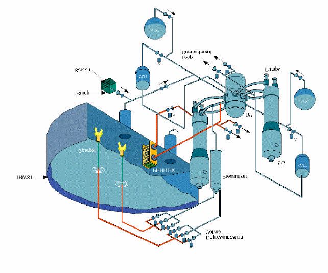
loss of feedwater, feedwater line breaks, and steam line breaks.The IRWST provides the heat sink for the PRHR HX. The IRWST water volume is sufficient to absorb decay heat for more than 1 hour before the water begins to boil. Once boiling starts, steam passes to the containment. This steam condenses on the steel containment vessel and, after collection, drains by gravity back into the IRWST. The PRHR HX and the passive containment cooling system provide indefinite decay heat removal capability with no operator action required. Passive containment cooling - The passive containment cooling system (PCS) (Figure 6) provides the safety-related ultimate heat sink for the plant. As demonstrated by computer analyses and extensive test programs, the PCS effectively cools the containment following an accident such that the pressure is rapidly reduced and the design pressure is not exceeded. The steel containment vessel provides the heat transfer surface that removes heat from inside the containment and rejects it to the atmosphere. Heat is removed from the containment vessel by continuous natural circulation flow of air. During an accident, the air cooling is supplemented by evaporation of water. The water drains by gravity from a tank located on top of the containment shield building. Calculations have shown the AP1000 to have a significantly reduced large release frequency following a severe accident core damage scenario. With only the normal PCS air cooling, the containment stays well below the predicted failure pressure for at least 24 hours. Other factors include improved containment isolation and reduced potential for LOCAs outside of containment. This improved containment performance supports the technical basis for simplification of offsite emergency planning. Containment isolation - AP1000 containment isolation is significantly improved over that of conventional PWRs. One major improvement is the large reduction in the number of penetrations. Furthermore, the number of normally open penetrations is reduced by 60 percent. There are no penetrations required to support post-accident mitigation functions (the canned motor reactor coolant pumps do not require seal injection, and the passive residual heat removal and passive safety injection features are located entirely inside containment). Long-term accident mitigation - A major safety advantage of the AP1000 versus current-day PWRs is that long-term accident mitigation is maintained by the passive safety systems without operator action and without reliance on offsite or onsite ac power sources. For the limiting design basis accidents, the core coolant inventory in the containment for recirculation cooling and boration of the core is sufficient to last for at least 30 days, even if inventory is lost at the design basis containment leak rate.
PCCS gravity drain
                                                                              Natural convection
                               water tank                                      air discharge

                                                                                      Water film evaporation

                        Outside cooling
                          air intake

                                                                                             Steel containment
                                                                                                 vessel
                            Air baffle

                                                  Internal condensation and
                                                      natural recirculation

                       Figure 6 - AP1000 Passive containment cooling system

       3.2 Severe accidents (Beyond design basis accidents)

In-vessel retention of molten core debris - In-vessel retention (IVR) of molten core debris
via water cooling of the external surface of the reactor vessel is an inherent severe accident
management feature of the AP1000 passive plant. During postulated severe accidents, the
accident management strategy to flood the reactor cavity with in-containment refueling water
storage tank (IRWST) water and submerge the reactor vessel is credited with preventing
vessel failure in the AP1000 probabilistic risk assessment (PRA). The water cools the
external surface of the vessel and prevents molten debris in the lower head from failing the
vessel wall and relocating into the containment. Retaining the debris in the reactor vessel
protects the containment integrity by preventing ex-vessel severe accident phenomena, such
as ex-vessel steam explosion and core-concrete interaction, which have large uncertainties
with respect to containment integrity.
The passive plant is uniquely suited to in-vessel retention because it contains features that
promote external cooling of the reactor vessel. Figure 7 provides a schematic of the AP1000
reactor vessel, vessel cavity, vessel insulation and vents configuration that promotes
IVR of molten core debris.
• The reliable multi-stage reactor coolant system (RCS) depressurization system results in low
stresses on the vessel wall after the pressure is reduced.
• The vessel lower head has no vessel penetrations to provide a failure mode for the vessel
other than creep failure of the wall itself.
• The reactor cavity can be flooded to submerge the vessel above the coolant loop elevation
with water intentionally drained from the in-containment refueling water storage tank.
Figure 7 - AP1000 Configuration to Promote IVR of Molten Core Debris
The reactor vessel insulation design concept provides an engineered pathway for
water-cooling the vessel and for venting steam from the reactor cavity.
The results of the AP1000 IVR analysis show that, with the AP1000 insulation designed to
increase the cooling limitation at the lower head surface and the cavity adequately flooded,
the AP1000 provides significant margin-to-failure for IVR via external reactor vessel cooling.
4. DESIGN FEATURES FOR OVERALL COST REDUCTION
The AP1000 is a logical extension of the AP600 design. The AP1000 maintains the same
design philosophy of AP600, such as use of proven components, systems simplification and
state-of-the-art construction techniques. The AP1000 optimizes the power output while
maintaining the AP600 NI footprint, to reduce capital and generation costs.
Simplification - AP1000 is an advance passive nuclear power plant that has been designed to
meet globally recognized requirements. A concerted effort has been made to simplify
systems and components, to facilitate construction, operation and maintenance and to reduce
the capital and generating costs.The use of passive systems allows the plant design to be significantly simpler than conventional pressurized water plants. In addition to being simpler, the passive safety systems do not require the large network of safety support systems found in current generation nuclear power plants (e.g., Class 1E ac power, safety HVAC, safety cooling water systems and associated seismic buildings). The AP1000 uses 50% fewer valves, 83% less pipe (safety grade), 87% less cable, 36% fewer pumps, and 56% less seismic building volumes than an equivalent conventional reactor. Simplicity reduces the cost for reasons other than reduction of the number of items to be purchased. With a fewer number of components, installation costs are reduced, construction time is shortened and maintenance activities are minimized. Construction Schedule- The AP1000 has been designed to make use of modern modular construction techniques. Not only does the design incorporate vendor designed skids and equipment packages, it also includes large structural modules (Figure 8) and special equipment modules. Modularization allows construction tasks that were traditionally performed in sequence to be completed in parallel. The modules, constructed in factories, can be assembled at the site for a planned construction schedule of 3 years – from ground- breaking to fuel load. This duration has been verified by experienced construction managers through 4D (3D models plus time) reviews of the construction sequence. Availability and O&M Costs - The AP1000 combines the best proven PWR technology with utility operating experience to enhance reliability and operability. Steam generators are similar to the recent replacement steam generators, canned motor pumps and rugged turbine generators are proven performers with outstanding operating records. The Digital on-line diagnostic instrumentation and control system features an integrated control system that avoids reactor trips due to single channel failure. In addition, the plant design provides large margins for plant operation before reaching the safety limits. This assures a stable and reliable plant operation with a reduced number of reactor trips (less than one per year). Based on the above, and considering the short planned refueling outage (17 days) and plans to use a 18 to 24-month fuel cycle, the AP1000 is expected to exceed the 93% availability goal. For AP1000 availability is enhanced by the simplicity designed into the plant, as described above. There are fewer components which result in lower maintenance costs, both planned and unplanned. In addition, the great reduction in safety-related components results in a large reduction in inspection and tests. Simplicity is also reflected in the reduced AP1000 staffing requirements.
Module Type          Number

                                                                 Structural            122

                                                                 Piping                154

                                                                 Mechanical            55

                                                                 Electrical            11

                                                                 ______________________

                                                                 TOTAL                 342

                             Figure 8 – Large Structural Module

As a reference figures the anticipated AP1000 electricity cost will be in the range of 3.0 to
3.5¢/kwh.

      5. AP1000 DEPLOYMENT
US Programs
The “Nuclear Power 2010” program sponsored by the DOE is expected to re-vitalize the
nuclear industry in USA, creating all conditions for initiating the construction of a new
nuclear power plant in USA by the year 2010. The goal of Nuclear Power 2010 is to support
industry initiatives to eliminate barriers to the deployment of a series of advanced nuclear
plants in the U.S. in the near term. The initiative encourages investment in projects that can
improve the economic competitiveness of new nuclear power plants.
The program is expected to effectively shorten the time between plant contract and power
operation. The required lead time for an advanced nuclear plant such as AP1000 after it has
been licensed is estimated to be approximately 5-6 years between the plant order and its
commercial operation. This includes approximately 3 to 4 years for construction, with the
remaining 2 years being required for the power company to order long lead items, prepare the
site and perform startup operations. The Early Site Permit (ESP) and Combined Operating
License (COL) are part of the U.S. licensing process established under 10 CFR Part 52 and
would be completed prior to the initiation of site activities.
Three US Power companies are currently engaged with the US NRC to complete an ESP for
three sites that could accommodate an advanced nuclear plant like AP1000. The ESP
licensing process is a significant milestone in the realization of new nuclear build in the US.
It has been projected that the US power companies will receive ESPs by 2005 thereby
allowing the completion of COL and initiation of new plant construction activities.
In response to the DOE program, Westinghouse has joined with Entergy, Exelon Southern,
Duke, Constellation, EdF, Florida P&L, TVA and GE in a group named NuStart Energy
Development, LLC.
The group has submitted proposal to U.S. Department of Energy (in Response to Nuclear
Power Solicitation) for a project to:
• Select a plant Site
• Prepare a COL application for W AP1000 and GE ESBWR
• Prepare project proposal for each design, including pricing and contractual
terms, for potential downselection in 2007
• Submit COL application(s) to NRC in 2008
• Obtain COL in (2010)
Project lays foundation for future decision on whether to construct.
The European Passive Plant Program
The European Passive Pressurized Water Reactor (EPP) Program was initiated in 1994
between several European utilities, Westinghouse and its Industrial Partner ANSALDO
Nucleare. The objective of the EPP Program is to develop a PWR Nuclear Island design
based on the Westinghouse passive plant technology and ensuring compatibility of the plant
design with the EUR as well as key European licensing requirements.
Since 2001, the EPP reference plant design is the AP1000. The EPP plant follows very
closely the AP1000 U.S. design, but it has implemented some of the design features
developed during the EPP program, including Low Boron capabilities, Auxiliary Systems
Design and the capability to operate with MOX fuel.
Merging the EPP and AP1000 programs provides a more cost effective way to achieve the
final objective of the EPP Program which is to develop a 1000 MWe PWR design based on
passive technology, that meets the EUR and is licensable in Europe.
The current EPP Phase, called Phase 2D, was initiated in December 2003 and will continue
through October 2005. The main focus of Phase 2D is:a. to assess the AP1000 design against the European Utility Requirements (EUR) and
cooperate with the EUR Organization in the generation of an AP1000 EUR Volume 3
subset,
b. to identify AP1000 design modifications required to comply with key EUR
requirements,
c. to provide support of AP1000 progress in the U.S.
As of today, all of the EUR Chapters have already been discussed within the EUR
Coordination Group. Based on the results of the compliance assessment, it can be stated that
the AP1000 design shows a good level of compliance with the EUR Revision C
requirements. The AP1000 program activities performed under the EPP Program further
confirm the potential capability of passive PWR technology in meeting the safety standards
established by the EUR while keeping a cost competitiveness objective.
China Bid
End of February 2005, Westinghouse presented a proposal to the China State Nuclear Power
Technology Corporation to build four AP1000 plants at two sites in China - San Men in
Zhejiang Province, and Yangjiang in Guangdong Province. The bid essentially encompasses
two twin-unit projects, technology transfer and initial fuel loads for all four plants. Ansaldo
Energia participates to this offer with a primary role between the Westinghouse partners.
6. CONCLUSION
On September 13th 2004, the US Nuclear Regulatory Commission granted, after a process
that lasted more than two years, the Final Design Approval (FDA) to the Westinghouse
AP1000 Nuclear Power Plant.
The FDA is a very important achievement for the AP1000 plant designed by Westinghouse
with the support of an international group of partners among the which Ansaldo Energia –
Nuclear Division has been played a major role.
AP1000, together with the AP600, is the only Advanced Plant that has obtained the FDA by
US NRC. The FDA represent an important advantage for the AP1000 commercialization in a
moment in which nuclear energy seems, once again, to be a mandatory choice for the future
energy mix in the industrialized countries.
The AP1000 is, today, a mature product and it is playing a major role in the world’s Nuclear
Energy arena.In U.S. the “Nuclear Power 2010” program sponsored by the DOE is expected to re-vitalize
the nuclear industry in USA, creating all conditions for initiating the construction of a new
nuclear power plant in USA by the year 2010.
In Europe, the on-going EPP Phase 2D activities are further establishing the AP1000 plant
design as a suitable design for Europe. AP1000 largely complies with the latest European
Utility Requirements while retaining the standard plant economic advantage of being largely
the same AP1000 plant design as for the U.S.
The EPP-AP1000 EUR compliance assessment and the “Nuclear Power 2010” are valuable
elements for sustaining a long-term positive view of nuclear power contributions to world’s
energy supply mix. It has become increasingly clear that nuclear power generation additions
are most competitive with other energy choices when a standard plant design can be applied
in multiple locations.
7. REFERENCES
1. J.W. Winters, J. A. Clelland, AP1000 Design And Construction Integration, ICAPP’04-4254, June
2004
2. E.W. Cummins, T.L. Schulz, Westinghouse AP1000 Advanced Passive Plant, ICAPP’04-4254, June
2004
3. G. Saiu, K.J. Demetri, European Utility Requirements (EUR) Volume 3 Assessment for AP1000,
ICONE13-50748, Bejing, May 2005
4. European Utility Requirements for LWR Nuclear Power Plants, Volume 1 & 2, Rev. C, April 2001You can also read