Successful Operation of Jinzhushan 3, the World's First PC-Fired Low Mass Flux Vertical Tube Supercritical Boiler
←
→
Page content transcription
If your browser does not render page correctly, please read the page content below
Technical Paper
BR-1849

                                   Successful Operation of Jinzhushan 3,
                                   the World’s First PC-Fired Low Mass
                                   Flux Vertical Tube Supercritical Boiler

Authors:
A.J. Bennett
M.J. Albrecht
C.S. Jones

Babcock & Wilcox Power
Generation Group, Inc.
Barberton, Ohio, U.S.A.

Q. Zhang

Babcock & Wilcox
Beijing Company, Ltd.
Beijing, People’s Republic of
China

Y. Chen

Datang Huayin Jinzhushan
Thermoelectricity Power
Generation Co., Ltd.
Hunan Province, People’s
Republic of China

Presented to:
Power-Gen Asia

Date:
November 2-4, 2010

Location:
Singapore, Republic of Singapore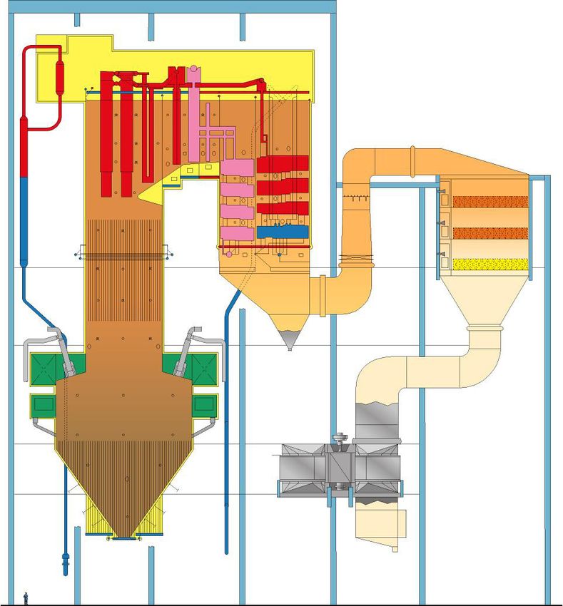
Successful Operation of Jinzhushan 3, the World’s First
PC-Fired Low Mass Flux Vertical Tube Supercritical Boiler
                                                         A.J. Bennett                               Y. Chen
                                                        M.J. Albrecht                       Datang Huayin Jinzhushan
                  Q. Zhang
                                                         C.S. Jones                          Thermoelectricity Power
    Babcock & Wilcox Beijing Company, Ltd.
                                                    Babcock & Wilcox Power                     Generation Co., Ltd.
      Beijing, People’s Republic of China
                                                     Generation Group, Inc.                 Hunan Province, People’s
                                                    Barberton, Ohio, U.S.A.                     Republic of China

Presented to:                                                                                                         BR-1849
Power-Gen Asia
November 2-4, 2010
Singapore, Republic of Singapore

Abstract                                                           Introduction
   June 2009 marked the initial coal-fired operation of the            In March 2007, Datang Huayin Jinzhushan Thermoelec-
world’s first supercritical pulverized coal-fired low mass         tric Power Generation Co., Ltd. placed an order with BWBC
flux vertical tube Benson® boiler. Jinzhushan 3, located           for the supply of a 600 MW supercritical steam generator
in Hunan Province in the People’s Republic of China, is a          as part of a planned expansion for their power plant located
600 MW Babcock & Wilcox Power Generation Group, Inc.               near the city of Leng Shuijiang in Hunan province of the
(B&W PGG) VTUP™ once-through boiler with vertical tube             People’s Republic of China. To efficiently utilize the plant’s
furnace construction designed to burn Chinese anthracite           low volatile anthracite coal, a downshot pulverized coal-
using downshot pulverized coal (PC) technology. The boiler         fired combustion system was required for the project. This
was supplied to the Datang Jinzhushan Fossil Power Gen-            was the first downshot boiler designed to take advantage of
erating Company by Babcock & Wilcox Beijing Company,               the higher plant efficiency of a supercritical pressure steam
Ltd. (BWBC) under license from B&W PGG.                            cycle. Modern supercritical boilers have typically used high
   Supercritical steam cycles are an integral part of low car-     mass flux spiral tube furnace designs that are inherently
bon electric generating strategies being deployed world-wide       resilient to furnace gas-side heat flux upsets. However, the
because of their inherently higher efficiency than traditional     complex geometry of the lower furnace burner zone makes
subcritical cycles. This paper reviews the development             it very difficult to adapt a spiral tube design to a downshot
history of supercritical, once-through steam generator tech-       boiler arrangement.
nology and product advancements. Spiral and vertical tube              BWBC is a joint venture company owned with equal
furnace circuitry designs for once-through variable pressure       shares by Beijing Jingcheng Machinery Electric Holding
boilers are compared and contrasted.                               Co., Ltd. and Babcock & Wilcox Power Generation Group,
   Downshot pulverized coal combustion technology is               Inc. (B&W PGG). BWBC licenses a full range of B&W PGG
used to efficiently utilize low volatile anthracite coal that is   utility boiler products and technologies focusing primarily
difficult to burn conventionally. The unique design features       on the China market and is a key partner supporting B&W
of the downshot combustion system are reviewed.                    PGG as a primary detail engineering and fabrication shop
   B&W PGG’s VTUP steam generator product and the                  for utility and industrial products sold world-wide. When
adaptation of this technology for the Jinzhushan 3 downshot        Jinzhushan 3 required supercritical boiler technology for a
application are described. Results from the successful 168         downshot arrangement, B&W PGG worked closely with
hour reliability run of the Jinzhushan 3 boiler completed          BWBC to develop a solution that utilized low mass flux,
on July 4, 2009, and subsequent performance testing are            vertical tube Benson boiler technology originally pioneered
presented.                                                         by Siemens AG. B&W PGG licenses this technology from
   The next development steps to use B&W’s VTUP tech-              Siemens and has further developed it into a commercial
nology, for downshot and wall-fired applications are also          product, the B&W PGG VTUP boiler. The low mass flux
presented.                                                         technology offers advantages of natural circulation flow

Babcock & Wilcox Power Generation Group                                                                                        1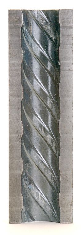
characteristics in the furnace tubes which can help self-        heater paths in the downpass. Major dimensions are shown
compensate for inherent upsets in heat absorption rates in       in Table 1.
the furnace. The vertical orientation of the tubes in the VTUP
boiler furnace panels was also much easier to adapt to the       Fuel analysis
lower furnace arrangement of the downshot boiler. Other
advantages include a lower furnace water/steam pressure             The coal is delivered from a mine near the plant. The
drop resulting in significant savings in the power consump-      design coal analysis is as follows:
tion of the feedwater pump as well as a simpler mechanical          The unique coal characteristics significantly influence
support system for the furnace and less complexity for shop
and field construction and fit-up.
                                                                      Ultimate (% wt)                Proximate (% wt)
    In July 2009, Jinzhushan unit 3 successfully completed              C                    49.60    VM                   3.82
its 168 hour test run and in September 2009, passed its                 H                     1.71    FC                  50.80
performance test, proving the successful application of the             O                     1.53    H2O                  9.39
world’s first supercritical, pulverized coal-fired low mass             S                     1.20    Ash                 35.99
flux vertical tube boiler. This successful demonstration
                                                                        N                     0.58
establishes B&W PGG’s VTUP low mass flux supercritical
boiler technology as a viable alternative supercritical steam          H2O                    9.39   HHV            19.4 MJ/kg
generation technology for the electric utility generation              Ash                   35.99
industry, whether for a downshot or wall-fired pulverized
coal application.                                                                  Ash Analysis (% wt)
                                                                                      SiO2                  53.97
                                                                                     Al2O3                  32.00
Jinzhushan 3 boiler description
                                                                                     Fe2O3                   4.18
   The Jinzhushan 3 boiler is designed to supply main steam
                                                                                      CaO                    2.72
to a 660 MW supercritical steam turbine generator set at a
                                                                                     MgO                     1.35
rate of 1900 ton/hr (4,189.5 klb/h) at 25.4 MPa (3683 psi)
and 571C (1060F) with reheated steam at 569C (1056F). A                              Na2O                    1.00
“Heater Above Reheat Point” (HARP) steam cycle is used,                               K2O                    1.86
providing feedwater to the boiler at 289C (552F). The B&W                             TiO2                   1.06
VTUP downshot boiler arrangement is illustrated in Fig.                               SO3                    1.86
1. The unit is a two pass once-through supercritical boiler
with a vertical tube membrane water wall furnace with a          the boiler design. The ash is primarily silica and alumina,
parallel down pass. Reheat steam temperature is controlled       which exhibits a very high ash fusion temperature minimiz-
by biasing flue gas between the reheater and primary super-      ing slagging concerns. However, because silica and alumina
                                                                 is very erosive in nature and the total content of the ash is
                                                                 very high, the gas velocities through the convection heating
                                                                 surface were designed to be very low, approximately 7.5
                                                                 meters per second.
                                                                     Low volatile anthracite requires a hotter furnace to sustain
                                                                 combustion compared to more common, higher volatile,
                                                                 lower rank coals. The downshot furnace with refractory
                                                                 lined burner zone provides an effective combination of
                                                                 long residence time and high temperature. The burners fire
                                                                 downward into the refractory lined zone of the furnace. The
                                                                 combustion products then turn upwards to leave the burner

                                                                                 Table 1
                                                                      Jinzhushan 3 Boiler Dimensions
                                                                  Furnace
                                                                    Width – 31.81 m
                                                                    Depth – 16.6/9.4 m (lower/upper)
                                                                    Height – 62.1 m
                                                                  Horizontal Convection Pass
                                                                    Reheater pass depth – 4.4 m
Fig. 1 Jinzhushan 3 VTUP downshot boiler.
                                                                    Primary SH pass depth – 6.6 m

2                                                                                     Babcock & Wilcox Power Generation Group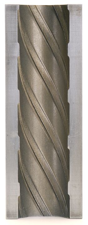
zone as shown in Fig. 2. As the flame turns upward to exit the
lower furnace, the char reactions return heat to the ignition
area, increasing the effectiveness of the combustion process.
The enlarged lower furnace also provides extended residence
time of the fuel particles allowing the slower burning char
to burn out more completely.
    B&W PGG and BWBC have designed and supplied many
downshot furnaces for subcritical boilers. However, there
is a special challenge when designing the downshot furnace
for a supercritical application. The spiral furnace geometry
traditionally used on variable pressure supercritical boilers
is very difficult to adapt to the complex arrangement of the
downshot furnace geometry. A vertical tube configuration
is needed to adapt to the lower arch or burner shelf of the
downshot furnace. To ensure that all the furnace tubes are ex-
posed to nearly even heat distribution through the refractory                                                     Sub-Critical

covered combustion zone, the corners of the lower furnace                                                           Square
                                                                                                                   Corners

are mitered as shown in Fig. 3. Subcritical downshot furnace
designs have typically used square corners.
    The furnace walls are constructed of vertically oriented
membrane tube panels. The lower section of the furnace uses                                                      Supercritical
                                                                                                                   Mitered
optimized multi-lead ribbed (OMLR) tubes and extends up                                                            Corners

to a set of transition headers at an elevation approximately
midway up the furnace shaft. The transition headers inter-       Fig. 3 Mitered furnace corners.
connect through mixing bottles which equalize the enthalpy           Reheat steam is first heated in the front section of the
entering the upper furnace panels. The upper furnace panels      horizontal convection pass then passes through the final re-
use smooth tubing. Riser tubes extend from the upper furnace     heater sections in the pendant convection pass. The reheater
enclosure headers to a manifold header where the fluid is        is arranged with double end inlet and outlet steam connec-
mixed and routed to two vertical steam separators.               tions at the headers. Reheat steam temperature is controlled
    The steam passes from the vertical steam separators          during steady-state conditions by biasing gas between the
through the furnace roof and then to the horizontal convec-      front and rear parallel gas passes in the horizontal convection
tion pass (HCP) enclosure walls and the rear pendant convec-     pass using dampers located at the boiler outlet. Attempera-
tion pass (PCP) enclosure panels. The steam from the rear        tion at the reheater inlet provides reheat steam temperature
roof header flows down the rear HCP wall and up the HCP          control during load transients.
side and front walls. The flow is then routed to the upper
baffle wall header and down the baffle wall to the primary
superheater inlet. The steam then flows through the primary      Combustion system (fuel and air systems)
superheater, the platen superheater in the furnace and finally      To supply pulverized coal to the burners, the boiler uses
the secondary superheater. Spraywater attemperators are          a direct firing system that includes twelve gravimetric coal
located at the platen and secondary superheater inlets.          feeders, six ball mill-type pulverizers and 24 B&W PGG half
                                                                 primary air exchange (H-PAX™) burners. Twelve burners
                                                                 are arranged on each front and rear wall burner shelf. Com-
    Fuel/Air                                                     bustion air is supplied by two axial flow primary air fans
                                                                 and two axial flow forced draft fans. Two trisector-type air
                                                                 heaters are used to preheat the combustion air. A selective
     Vent Air                                                    catalytic reduction (SCR) system with two initially installed
                                                                 layers and space for one future layer of catalyst is located
                                                                 above the air heater. The balance of the flue gas and emis-
                                                  Particle
                                                 Heating,        sions control system includes an electrostatic precipitator
    Staging Air
                                              Drying and
                                           Devolatilization
                                                                 (ESP) and two axial flow ID fans per unit.
     NOx Controlled
     by Multi-Step
     Air Supply
                                              Main Flame
                                             Development         Boiler startup system
                                                                    A schematic of the boiler water-steam and startup sys-
                                                                 tem arrangement is shown in Fig. 4. The startup system
                                                                 equipment consists of two steam water separators, a water
Fig. 2 Downshot furnace.                                         collection tank, a boiler circulating pump and the associated

Babcock & Wilcox Power Generation Group                                                                                          3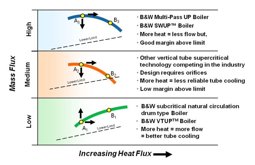
piping and control valves to return the fluid from the water    required mass flow is maintained. Steam generated through
collection tank to the economizer inlet.                        the furnace circuits is separated from the water in the verti-
   During startup, the unit is operated much like a drum        cal separator, routed to the superheater and then to either
boiler where water is recirculated to maintain a minimum        the steam turbine or the turbine bypass system. The water
flow through the furnace equivalent to 30% of full load flow.   from the vertical separator is returned to the water collec-
The system is similar to a pumped circulation drum boiler       tion tank and then to the circulating pump. The 381 valve,
with the steam water separators and the water collection        located at the discharge of the circulating pump, controls
tank functioning like the steam drum. The water flowing         the flow proportionally to tank level to maintain the water
through the furnace is a combination of water from the water    inventory in the collection tank. Water is also recirculated
collection tank and boiler feedwater. The boiler feed pump      from the pump discharge to the collecting tank to assure that
controls the total flow through the furnace so the minimum      the minimum flow required through the pump is maintained.

Fig. 4 Steam/water circuitry and startup system.

4                                                                                   Babcock & Wilcox Power Generation Group
Above the minimum boiler load (or Benson load) the unit
switches to once-through operation. The circulating pump
is taken out of service but is kept pressurized. A small flow               Coal
                                                                                                                50% of Primary Air
                                                                                                                 85%-90% of Coal

of feedwater from the economizer outlet is routed to the
                                                                             and
                                                                       Primary Air

circulating pump inlet and back to the separator to maintain
the components in the ready state for use during shutdown.
                                                                                        H-PAX Vent
                                                                                     50% of Primary Air
                                                                                      10%-15% of Coal

Boiler technology background

Downshot combustion system for low volatile
                                                                                                                               Sliding
                                                                                                                             Air Damper

coal
                                                                                                   Secondary
    China has one of the largest reserves of anthracite coal                                          Air

in the world. Anthracite is a dense, hard, brittle and homog-
                                                                                                   Inner Zone
                                                                                                    Spin Vane

enous type of coal which has relatively higher heating value
(HHV) than lower rank coals. It has the highest fixed carbon
                                                                                                   Outer Zone
                                                                                                   Spin Vane

and the lowest volatile matter of any coal type. The low
volatile matter content makes anthracite difficult to ignite
and slow burning. The ratio of fixed carbon (FC) to volatile
matter (VM) is known as the fuel ratio, and is often used to
compare the relative combustion characteristics of different
                                                                   Fig. 5 H-PAX burner.
coals. A coal with a high fuel ratio is typically more difficult
to burn. The fuel ratio for anthracite coal is typically 10:1
whereas this ratio for typical bituminous or lignite coals is      particle fineness which increases the heating rate of the coal
in the range of 1:1 to 2:1.                                        particles. The H-PAX burner is equipped with B&W PGG’s
    B&W PGG determined that FC and VM alone are not                enhanced ignition dual register system which recirculates
good indicators of whether a fuel is difficult to burn. Even       gases from the char reaction zone back to the ignition zone
reactive (low fuel ratio) coals have proven to be difficult to     of the flame. Finally, the H-PAX burner develops a fuel-rich
burn if there is excessive moisture and/or ash. This is be-        zone near the high temperature secondary air layer which
cause high inorganic content can inhibit carbon utilization        provides more efficient heating of the coal particles. Staging
by providing a heat sink and interfering with the opportunity      air is injected below (downstream of) the vent air, as shown
for combustible portions of the fuel to come in contact with       in Fig. 2, to minimize nitrogen oxides (NOx) formation.
the oxygen. B&W PGG has developed an empirical igni-
tion factor derived from full-scale experience with difficult
coals. This factor relates variations in fuel ratio, moisture      Supercritical boiler
content, ash content, and coal heating value to ignition              Babcock & Wilcox's (B&W) research in once-through
behavior. This factor allows the accurate matching of the          boilers began at the company’s Bayonne, New Jersey,
proper burner to the fuel.                                         laboratory in 1916. B&W increased its research work and
                                                                   in 1951, established another heat transfer test facility in Al-
                                                                   liance, Ohio, capable of operating at 34.5 MPa (5000 psi).
H-PAX burner                                                          The vision of the high efficiency, supercritical power
   B&W PGG has pioneered the use of the H-PAX burner               plant was also shared by American Electric Power (AEP) and
for use with burning low volatile coals (Fig. 5). The H-PAX        General Electric (GE). AEP entered into a contract with both
burner includes several features to improve ignition of the        B&W and GE to build the world’s first ultra-supercritical
low volatile anthracite coal. First, the fuel-air temperature      power plant. With the commencement of commercial opera-
in the ignition zone is increased by directing a portion of        tion of the B&W® 125 MW Philo steam generator in 1957,
the low temperature primary air away from the coal at              the United States (U.S.) electric utility industry moved into
the burner nozzle and injecting it later in the combustion         the supercritical era.
process. This diverted portion of primary air is referred to          During the 1960s there was rapid growth in power plant
as vent air. Extracting the vent air reduces the amount of         size with most of the large units using the supercritical
heat needed to support the ignition of the fuel-air mixture,       steam cycle. During this period, B&W’s once-through
improving the effectiveness of the ignition process. The           boiler design capability grew from 125 MW to more than
velocity of the pulverized coal stream through the burner          1100 MW. The year 1972 marked the startup of the world’s
nozzle is determined empirically to optimize the ignition of       largest supercritical boiler, the B&W 1300 MW unit at TVA
the fuel while providing long residence time of the fuel in        Cumberland. During the next 18 years, B&W supplied and
the ignition zone. The pulverizers supply the coal with high       started up eight (8) additional 1300 MW units, including the

Babcock & Wilcox Power Generation Group                                                                                                   5
AEP Mountaineer unit which holds the world record of 607 Guohua Diandong Power Co for their Diandong power plant
days of continuous operation without an outage. located in Yunnan Province. B&W PGG and BWBC have
The U.S. utility market originally used supercritical sold a total of 37 anthracite-fired downshot units (16,800
units for base load duty only, so constant furnace pressure MW) to customers in Canada, China and Vietnam.
operation was not a concern. However, today’s market in With the central utility planning for China requiring the
the U.S. and world-wide favors units capable of full vari- use of the more efficient supercritical steam cycle technol-
able pressure furnace operation, which allows the flexibility ogy for new coal-fired power plants, B&W PGG and BWBC
to operate the units either as base-loaded or with on/off or developed an enhanced version of its 600 MW downshot
load cycling. B&W brought the first fully variable pressure boiler by adapting B&W PGG’s VTUP boiler technology.
operation-capable unit to the U.S. by converting the Jack- The differences between a natural circulation and a once-
sonville Electric Authority Northside Unit 1 from a constant through boiler are shown in the simplified configurations
pressure to a variable pressure operating unit with a spiral illustrated in Fig. 6. In a natural circulation drum boiler, the
wound furnace in 1981. B&W grew its experience base for steam flow from the boiler is controlled by the fuel firing
the variable pressure supercritical spiral wound furnace rate. The steam temperature from the boiler depends on the
design with its supply of 2 x 425 MW supercritical units in sizing of the superheating surfaces in the boiler. The flow
Australia, several units in North America ranging from 530 of the fluid within the furnace tubes is obtained through the
to 800 MW, and BWBC’s supply of 350, 600 and 1000 MW density difference between the steam-water mixture in the
units in China. Currently B&W PGG and BWBC have more furnace tubes and the water in the downcomers of the circu-
than 26,500 MW (41 units) of variable pressure supercritical lation system. Adequate circulation flow within the furnace
units in operation or under contract. tubes must be obtained to properly cool the furnace enclosure
B&W PGG now extends its supercritical experience to tubes. With a once-through boiler furnace, the steaming rate
the vertical tube universal pressure (VTUP) supercritical of the boiler is established by the flow from the boiler feed
boiler. The concept of a low mass flux once-through variable pump, and the superheat temperature is controlled by the
pressure furnace design was first introduced by Siemens in feedwater flow rate in conjunction with the fuel firing rate.
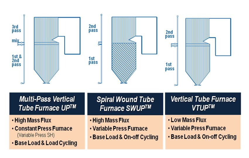
the 1990s. B&W PGG has performed extensive research B&W PGG has developed several types of furnace
over many years and developed a commercial design for designs for once-through fossil fuel boiler applications.
pulverized coal applications based on the Siemens concept. Fig. 7 provides a comparison of the three (3) basic types
This research included laboratory testing, in-furnace heat of B&W PGG once-through boiler furnaces. B&W PGG
flux testing, as well as detailed thermo hydraulic perfor- has experience with both vertical tube and spiral wound
mance modeling. The concept of a low mass flux vertical furnace designs. The multi-pass vertical tube design was
tube furnace has been applied in the industry for subcritical developed in the late 1950s and has been proven by more
once-through PC boiler applications. A supercritical low than 600 designed and operating worldwide. B&W PGG’s
mass flux design adds a special challenge as fluid side heat multi-pass design, known as the UP boiler, utilizes multiple
transfer rates reduce when the furnace is operated near criti- flow passes in the furnace with a constant pressure high
cal pressure (22.1 MPa/3208 psig). B&W PGG’s design has mass flux furnace design. The multi-pass UP uses variable
been proven by more than a year of successful operation of pressure operation in the superheater to match the variable
the world’s first supercritical PC-fired low mass flux VTUP pressure requirements of the steam turbine over the operat-
boiler, Jinzhushan unit 3. ing load range.
In addition to the Jinzhushan unit 3 project, BWBC has The proven spiral wound boiler design has been used
four other downshot-type VTUP boilers under contract. worldwide on over 425 designed and operating units. The
China Guodian Corporation Xingyang units 1 and 2 are
scheduled to achieve first fire in late 2010 and early 2011.
Natural Circulation Once-Through
Guizhou Xingyi Power Development Xingyi units 1 and 2 (Drum) (Benson)
are scheduled to start up in 2012. All are 600 MW downshot
units with steam conditions of 571C /569C (1060F/1056F).
In addition to the downshot contracts, the technology is ready
to be applied to a wall-fired design project.
Advanced VTUP furnace circuitry
Evolution of the Downshot Circulation Design for
Jinzhushan 3 B&W PGG’s development of the downshot
boiler in China started in 1986 with the sale of 2 x 350 MW
subcritical natural circulation-type boilers to Huenang Inter-
national Power Development Corporation for the Shang-an
power plant. In 2003, the product was scaled up to 600
MW when BWBC sold four subcritical downshot boilers to
Fig. 6 Boiler circulation types.
6 Babcock & Wilcox Power Generation Group
Fig. 7 B&W supercritical, once-through boiler designs.
Fig. 8 Mass flux effects.
B&W PGG spiral furnace design, known as the SWUP™ SWUP boilers, the medium mass flux furnace design has a
boiler, utilizes a spiral wound furnace where the tubes are lower design margin.
wrapped around the furnace periphery at a specific angle By contrast, the B&W PGG VTUP design has natural
so that each tube in the spiral portion of the furnace makes circulation characteristics, where the mass flux of the fluid
approximately one turn around the boiler walls. The wrap- in the tube increases with increasing heat flux to provide an
ping of the tubes around the furnace provides nearly equal increased cooling effect for tubes that are exposed to heat
heat absorption for each tube in the spiral portion. This flux surges. This effect provides a natural self-adjustment
averaging effect minimizes the heat absorption difference characteristic that is more resistant to the inherent varia-
encountered by tubes around the furnace perimeter in a tions in combustion within the furnace from unexpected
vertical tube furnace resulting from the inherent imbalances turbulence as well as different burner and pulverizer firing
in the combustion system. The spiral wound furnace tubes combinations and when changing from one fuel to another.
typically transition to vertical tubes in a region of the furnace The low mass flux design will also result in more even
just below the furnace arch. The vertical tubes in the upper enthalpy leaving the tubes around the furnace perimeter,
furnace run from this transition point up to the furnace roof. and tube metal temperatures will be more balanced than
The B&W PGG SWUP boiler has the advantage of oper- with other vertical tube type variable pressure furnaces.
ating with full boiler variable pressure and is used for base Therefore, the B&W PGG VTUP furnace design was chosen
load, load cycling and on/off cycling operation. The newest for Jinzhushan 3. The low mass flux and the vertical tube
once-through design offered by B&W is the low mass flux geometry provided a combination of features that best fit the
vertical tube VTUP boiler, which also operates with variable needs of the supercritical downshot application.
furnace pressure and can be used for base load, load cycling The low mass flux feature provided lower overall furnace
and on/off cycling operation. pressure drop and natural circulation characteristics across
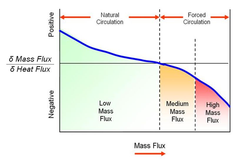
Another type of furnace design using vertical tubes that all boiler operating loads. The natural circulation charac-
has been recently developed and supplied in the industry is teristics allows for the fluid flow to distribute itself to the
the medium mass flux furnace design. The promising and furnace circuits based upon each circuit’s heat absorption.
evolving development of the VTUP was compared to a Circuits with more heat absorption draw more flow. One of
medium mass flux furnace design. As shown in Fig. 8, the the disadvantages of the multi-pass, spiral and medium mass
medium mass flux furnace design exhibits negative or forced flux designs is a higher furnace pressure drop, which requires
circulation flow characteristics. With forced circulation flow
characteristics, the mass flux of fluid within a tube decreases
when the heat applied to that tube increases. This reduced
mass flow in tubes exposed to higher heat flux upsets in a
medium mass flux furnace results in less cooling and a hotter
tube, potentially risking overheat failure of that tube. This
can result in a less conservative design that will require
a specific and detailed circuit orifice strategy to ensure
adequate distribution of flow to all circuits of the furnace
needed to achieve sufficient cooling of those circuits over the
load range and operating conditions for the unit. As shown
in Fig. 9, the medium mass flux circulation design does not
provide much design margin over the lower design limit for
a given furnace tube. In comparison with the high mass flux
furnace design such as the B&W PGG’s multi-pass UP and Fig. 9 Circulation characteristics of design mass flux.
Babcock & Wilcox Power Generation Group 7
greater feed pump power, reducing the net generating ef-
ficiency of the supercritical steam cycle. Other drawbacks of
the multi-pass vertical tube furnace design are that it is not
capable of full variable furnace pressure operation, reducing
the cycle efficiency at partial loads. The multiple pass and
spiral furnace configurations are also not easily adaptable to
the unusual furnace geometry of the downshot boiler. The
VTUP furnace design proved to be the most advantageous
fit for the Jinzhushan downshot boiler.
    Advantages of the B&W PGG VTUP furnace design
include:
     • Full variable pressure operation - best net heat rate
       at all loads
     • Same gas-side arrangement as subcritical and other
       supercritical designs
                                                                  Fig. 10 Jinzhushan 3 heat flux profile.
     • Natural circulation flow characteristics (flow increases
       with heat absorption)
     • Low tube-to-tube temperature differences at the fur-       11 shows typical stability plots for two different front wall
       nace circuit exits                                         circuits in the Jinzhushan furnace at the 40% load case. The
     • Low water-steam pressure drop - feed pump power            stability graphs show that flow variations caused by a heat
       savings (more than 1MPa lower pressure drop than           disturbance to the circuit diminish relatively quickly without
       high mass flux designs)                                    the need for additional equalization/stabilization measures
     • Simple construction and support system - easier to         such as the use of tube inlet orifices or an equalization/
       manufacture, erect and maintain                            stabilization header.
     • Good fuel flexibility – can be designed to operate with
       a wide range of coals
                                                                  Jinzhushan 3 operating results
     • Forgiving operation – can accommodate a wide range
       of upset operating conditions                                  The Jinzhushan unit 3 boiler completed its 168 hour
                                                                  reliability run on July 4, 2009. The boiler performance test
                                                                  was completed on September 12, 2009. The performance
Application of B&W PGG VTUP to the Jin-                           test results show all design values were achieved. Emissions
zhushan downshot furnace design                                   values of 700 to 900 mg/Nm3 for NOx were obtained. Boiler
    The Jinzhushan 3 downshot furnace design has an ar-           efficiency was 91.7%, which exceeded the guarantee of
rangement with 35mm OD OMLR SA213T12 tubes in the                 91.1%. The carbon content of the fly ash was 3 to 4 % which
lower furnace and 28mm OD smooth 15CrMo tubes in the              makes the fly ash marketable for the concrete industry. The
upper furnace. The fluid leaving the lower furnace tubes is       carbon content of the bottom ash was 2 to 3%.
fully mixed before entering the upper furnace tube circuits.          The two keys to once-through boiler furnace water-side
The tubes in the burner zone region of the lower furnace          design are maintaining uniform tube-to-tube temperatures
are covered by refractory. Since the furnace cross-section        and maintaining adequate heat transfer on the inside of the
is rectangular and the corners are mitered, the heat flux         tubes in high heat flux areas. The Jinzhushan boiler operation
around the furnace perimeter was carefully assessed and           shows that both of these design goals are met.
applicable adjustments were made in the evaluation of the             Fig. 12 shows the measured fluid temperatures at the
circulation design. Heat flux variations due to potential upset   outlet of the lower furnace at 450 MW and 600 MW load
conditions were also evaluated to achieve acceptable metal        conditions. The largest temperature differential between
temperatures at all loads. Computational combustion models        tubes is 18C. Historically, many vertical tube once-through
of the furnace design were developed to obtain vertical and       boilers operating at subcritical pressures would have tube-
horizontal heat flux distributions. Fig. 10 shows the heat flux   to-tube temperature differentials in excess of 80C. High
distribution in the Jinzhushan 3 furnace for full load firing     tube-to-tube differentials produce severe stresses which
conditions with all burners in service.                           can, in turn, lead to possible tube failures. The low tube
    The circulation design was evaluated for loads from 30        temperature differentials indicate that the low mass flux
to 100% of the maximum rated load for the boiler (BMCR).          natural circulation design concept used for the Jinzhushan
Balanced and unbalanced firing schemes were evaluated             3 boiler is operating as expected.
and used for checking the maximum expected tube metal                 B&W PGG installed heat flux instrumentation and ad-
temperatures for the operating range of loads. Stability          ditional thermocouples on the lower furnace to help evaluate
evaluations were performed on the unit for the most severe        the functional operation of the VTUP furnace. The heat flux
circuits in the lower furnace. The tube stability within the      instrumentation was installed in critical areas above the
panels as well as the panel to panel stability were met. Fig.     refractory covered burner zone (Fig. 10). Measurements

8                                                                                        Babcock & Wilcox Power Generation Group
Fig. 12 Lower furnace outlet fluid temperatures.

                                                                     Ribbed tubing has been used for many years in high
                                                                 heat flux zones of boiler circuits to create turbulence along
                                                                 the tube wall, cooling the tube to prevent overheating that
                                                                 can be caused by departure from nucleate boiling (DNB).
                                                                 Traditionally, the extruded multi-lead ribbed (MLR) type
                                                                 tubing has been used for once-through supercritical fur-
                                                                 nace panels. Siemens has developed a specification for an
                                                                 optimized multi-lead ribbed (OMLR) tube that can also
                                                                 be extruded which provides more effective cooling, but is
                                                                 more expensive to produce and has higher pressure drop
                                                                 characteristics than MLR tubes.
                                                                     B&W PGG uses an MLR tube specification that is similar
                                                                 to the OMLR tube in rib height, differing from the OMLR
                                                                 tube primarily by the larger rib lead angle. Fig. 13 shows
                                                                 the differences between two similar sized MLR and OMLR
                                                                 tubes. As a result of the reduced rib lead angle, the OMLR
                                                                 tube will have a higher pressure drop for an equivalent
                                                                 tube size and length when compared to the MLR tube. The
                                                                 heat transfer performance of the OMLR has been shown
Fig. 11 Jinzhushan 3 circuit stability plots.
                                                                 to be somewhat better than the MLR tube. However, when
                                                                 evaluating alternative furnace designs, the mass flux required
indicate that heat flux values are in line with values used to   to meet the design metal temperature of the tube using an
design the furnace metals.

Future development of the downshot VTUP
furnace design
                                                                                                                               Equivalent Rib
    Since the successful operation of Jinzhushan 3, B&W                                                                           Height
PGG has been advancing the circulation design of the
furnace. Future projects will utilize B&W PGG’s patented
concept of incorporating multiple lead ribbed (MLR) tubes
within the furnace design where different combinations of
ribbed (MLR and/or OMLR) and smooth tubes can be used
in sliding pressure once-through boiler furnace circuits to
optimize the circulation performance. A combination of                                                                          Reduced Rib
tube types can be selected based on the best evaluation of                                                                       Lead Angle
economics while providing a design that meets required
tube metal temperatures across the load range of the boiler.
The optimized furnace design typically has lower furnace
pressure drop and better flow stability at lower loads while
still maintaining natural circulation flow characteristics at        B&W Multi Lead Rib Tube   Optimized Multi Lead Rib Tube

all loads. In most cases, the B&W PGG MLR tube can be
used without the OMLR tubing.                                    Fig. 13 Multi-lead rib tubes.

Babcock & Wilcox Power Generation Group                                                                                                         9
MLR tube is almost equivalent to that required using an
OMLR tube.
In Fig. 14, the performance of the MLR to OMLR tube
is shown for a typical furnace design. These curves show
the minimum required mass flux for a typical furnace tube
throughout the load operating load range. The performance
of the OMLR and the MLR tubes can be seen to be similar
except between approximately 50 to 75% load. The furnace
is typically operating at critical pressure near 70% load. The
upset heat flux value used in this figure is determined at
selected load points and represents the maximum heat flux
expected in the critical regions of the furnace wall. The mass
flux data for the curves in Fig. 15 are based on using the upset
heat flux and the furnace operating pressure for each load.
The mass flux data for the curves in the figure is generated
for an OMLR and MLR tube of the same size. Since the
mass flux required for the furnace would be set by meet-
ing the minimum mass flux at all loads, and the difference
in minimum mass flux between MLR and OMLR tubes is
relatively small, a tube size can be selected that would allow
the use of either type of tube. Therefore, a furnace design
can be optimized to use MLR, OMLR or a combination of
OMLR and MLR. Because the MLR tube has lower pres-
sure drop characteristics than the OMLR tube, a design that
can use MLR tubing will have a performance advantage.
The next generation of downshot furnaces will incorpo-
rate the use of MLR tubing in combination with OMLR in
the furnace circuits. The circulation design results in a boiler
that has a slightly higher overall average mass flux through
Fig. 15 Circuit stability improvement with combination of MLR and
the furnace circuits, but will still have natural circulation OMLR tubes.
characteristics, a lower overall pressure drop and a boiler
design that has better stability characteristics at low loads.
Fig. 15 shows that an unstable circuit that uses all OMLR furnace circuit would be stable. Improved flow stability
tubes can be made stable by using a combination of OMLR with the OMLR and MLR furnace design is achieved by
and MLR in the lower furnace. For this application, the incorporating the lower pressure drop characteristics of the
results shown in the upper stability plot in Fig. 15 show MLR tube in the appropriate locations of the furnace while
the unstable flow characteristics for a furnace circuit that is still maintaining good heat transfer characteristics within the
designed with only OMLR tubing. Correcting the instability furnace. Use of all MLR for the entire lower furnace may
would normally require either using an equalization/stabili- also be developed in the future.
zation header or circuit tube inlet orifices. However, by using
the OMLR and MLR furnace design, the flow characteristics
given in the lower stability plot in Fig. 15, show that the VTUP PC wall-fired design
B&W PGG has used the experience gained from the suc-
cessful operation of the furnace design of the Jinzhushan unit
3 downshot supercritical boiler, to adapt the VTUP design
for wall-fired pulverized coal applications. A traditional PC
wall-fired boiler has some additional challenges, but the
principles of design and operation proven on the downshot
design remain the same.
A wall-fired PC boiler does not have refractory cover-
ing the furnace walls in the burner zone like the downshot
design. Therefore, the furnace tubes are exposed to high
rates of heat flux over a larger portion of the tube wall. As
a result, the enthalpy rise of the fluid passing through the
furnace tubes is greater and the upset steam temperatures
leaving the lower furnace tend to be higher. However, the
Fig. 14 Comparison of MLR to OMLR tubes. thermohydraulic principles of the VTUP design remain the
10 Babcock & Wilcox Power Generation Groupsame and are predictable and repeatable. In a wall-fired ap- for the current market in the U.S. have been developed for a
plication, the tube materials may need to be of a higher alloy project in which B&W PGG is supplying a boiler designed
grade, and/or the tube diameter and the mix of materials may with outlet steam conditions of 26.1 MPa (3785 psi) and
be somewhat different than on the downshot. 602C/608C (1116F/1126F). These USC steam conditions are
Additionally, the path and geometry differences between approaching a practical upper limit for steam temperatures
straight tubes and tubes bent around burner openings, is while still allowing use of ferritic outlet header materials.
more significant on a wall-fired boiler than a downshot. In For significantly higher service temperatures, advanced
a wall-fired boiler burners are arranged in columns such that austenitic steels or nickel based super alloys will be needed.
the tubes that run through those burner columns must bend Nickel based alloys offer an alternative to austenitic steels,
around multiple burner openings, while tubes between burn- but are higher in cost and the expense needs to be evaluated
ers remain straight. The relative resistance to flow through and justified. The key technology improvement needed to
the tubes located in the burner column is significantly greater realize the A-USC plant is the development of stronger,
than in a downshot unit where there is typically only one high-temperature materials, capable of operating under high
burner opening to pass around. This means that there is stresses at very high temperatures.
inherent potential for a wider range of flow between tubes Either the spiral wound SWUP or vertical tube VTUP
in a given circuit. However, this resistance can be modeled furnace design can be used for the A-USC boiler design.
and predicted accurately such that tube size and materials Selection of the type of furnace design will be based on an
can be selected to accommodate this difference. economic evaluation of required materials of construction
B&W PGG has developed a 600-700 MW VTUP design and functional performance for each alternative.
for a PC wall-fired application which will utilize only MLR Europe, Japan, and the U.S. all have programs to develop
tubes and does not require any OMLR tubes. The design materials for use in advanced ultra-supercritical power
will still have natural circulation flow characteristics to plants. The goal of the European Thermie AD 700 program
accommodate heat flux upsets in the furnace and operates on advanced steam power plants is to identify materials for
with stable flow at low loads. The VTUP furnace can also use in steam at 700C/720C (1292F/1328F), 37.5 MPa (5438
be applied to 350 to 1000 MW PC-fired boilers and can be psi). The Japanese Cool Earth initiative is attempting to de-
used for a variety of world-wide coal types. The operational velop coal-fired power plants capable of operating at a range
characteristics of the furnace for these boilers are expected of temperatures from 700C (1292F) to 750C (1382F). The
to be similar to the Jinzhushan 3 downshot boiler and will U.S. DOE/OCDO project has a goal of developing materials
offer the same advantages as those of the downshot VTUP for a 732C/760C (1350F/1400F), 350 bar (5075 psi) plant.
furnace design. All of the programs have multiple facets for development and
testing which lead up to the goal of a commercial advanced
ultra supercritical plant.
Advanced steam cycles The European program has completed first round testing
Today’s new coal fired power plants are also facing in a component test facility. The COMTES700 project was
greater pressures to minimize carbon dioxide (CO2) emis- completed at the Scholven F Plant of E.ONKraftwerke, in
sions leading to more focus on carbon capture and seques- Gelsenkirchen, Germany. The test loop consists of an HP
tration (CCS) technologies which reduce the net generation bypass valve, startup valve, stop valve, safety valve, and
efficiency of the plant. To minimize the efficiency impacts evaporator and superheater panels. It produces up to 36
of CCS there is an international drive for advanced ultra tons/h (79.4 klb/h) of steam at temperatures greater than
supercritical (A-USC) plants with ever higher efficiency. 700C (1292F) and pressures up to 220 bar (3190 psi). The
The situation in the U.S. is used as an example. The net ef- COMTES700 test loop had been in operation since July
ficiency of the current fleet of coal-fired plants in the U.S. 2005. Subsequent inspections found cracking in alloy 617
is around 36 to 39% (HHV). The goal of the U.S. advanced material. These results emphasize the need for further de-
plant development project is to achieve net efficiencies in velopment. Eon, Gelsenkirchen, Germany, had previously
the range of 46 to 47% (HHV). Increasing cycle efficiencies announced the planned development of a 500 MW A-USC
to these levels along with advancing the CCS technology demonstration plant at Wilhelmshaven. This 700C plant
should nearly offset the increased parasitic energy of the which would have started in 2014 is now delayed due to
CCS process and bring net plant efficiencies for new A-USC market conditions and technical reasons.
plants equipped with CCS in line with the current aggregate B&W PGG is a consortium member of the U.S. Depart-
fleet efficiency. ment of Energy (DOE) / Ohio Coal Development Office
The current state-of-the-art for supercritical units (OCDO) “Boiler Materials for Ultra Supercritical Coal
have main steam temperatures ranging up to about 605C Power Plants” program. The specific objectives of the Ultra
(1121F), and hot reheat temperatures ranging up to about Supercritical Materials Project are to:
620C (1148F). The highest main steam pressures of about • Identify materials performance issues that limit operat-
30.5 MPa (4423 psi) have been designed in Europe while ing temperatures and thermal efficiency of coal-fired
the highest main steam and reheat temperatures have been electricity generating plants.
commissioned in Japan. The most advanced cycle conditions • Identify improved alloys, fabrication processes, and
Babcock & Wilcox Power Generation Group 11coating methods that will permit boiler operation of in pulverizer operating conditions. The VTUP boiler offers
steam temperatures up to 760C (1400F) and steam a solution that takes advantage of the benefits of natural
pressures up to 37.9 MPa (5500 psi). circulation where tubes exposed to surges in heat flux will
• Work with alloy developers, fabricators, equipment draw more flow to cool the tube instead of reducing flow due
vendors and power generation plants to develop cost to higher resistance. The successful operation of Jinzhushan
targets for the commercial deployment of the alloys 3 demonstrates that this process works as expected and offers
and processes developed. an alternative that has advantages of simpler construction,
• Define issues impacting designs that can permit power a less complicated wall support system, and lower furnace
generation at temperatures greater than or equal to pressure drop contributing to more efficient net plant elec-
870C (1600F). tric generation. Both the SWUP and VTUP furnace designs
• Lay the groundwork for ASME Code approval. represent good alternative technologies for supercritical
The U.S. DOE/OCDO project is proposing COM- boiler applications that can be used to meet the needs of the
TEST1400, a component test facility similar to the European modern power plant.
COMTES700, for demonstrating proof of concept for very
high temperature components. The test facility, which is
proposed to be in a slip stream off of an operating unit, References
would operate at up to 350 bar (5075 psi) and 760C (1400F). 1. J.W. Smith, “Babcock & Wilcox Company Super-
The proposed timeline for the COMTEST1400 project is critical (Once-Through) Boiler Technology,” published
between 2010 and 2015. The experience gained from the 1998.
component test facility would lead into future projects for 2. DK McDonald/Jean-Pierre Tranier – Oxy-Coal is
an air-fired A-USC demonstration plant, and subsequently Ready for Demonstration – Babcock & Wilcox/Air
a demonstration of an oxy-combustion A-USC plant. The Liquide – 35th International Technical Conference on
air fired A-USC demonstration plant is proposed to operate Clean Coal & Fuel Systems.
from 2015 to 2020 while the oxy-combustion A-USC dem- 3. J. Wheeldon - Engineering and Economic Evalua-
onstration should take place in the 2020 to 2025 time period. tion of 1300°F Series Ultra-Supercritical Pulverized
Coal Power Plants: Phase 1 EPRI - Technical Update,
March 2008.
Summary 4. R. Viswanathan, J.F. Henry, J. Tanzosh, G. Stanko,
Both the SWUP and VTUP boiler designs can be supplied J.Shingledecker, and B. Vitalis, “U.S. Program on
to meet the market requirements of today’s supercritical Materials Technology for USC Power Plants,” Fourth
pulverized coal applications. The SWUP boiler represents International Conference on Advances in Materials
a well-proven solution that provides consistent heat dis- Technology for Fossil Power Plants, October 2004,
tribution to all tubes flowing through the furnace circuits Hilton Head, South Carolina, U.S.A.
making it insensitive to the natural variations that occur in 5. A.J. Bennett, P.S. Weitzel, “Boiler Materials for Ultra
furnace heat flux patterns that result from variations in fuel Supercritical Coal Power Plants Task 1B, Conceptual
characteristics and types burned, boiler cleanliness condi- Design, Babcock & Wilcox Approach” – Topical Re-
tions, air staging for combustion NOx control, and changes port, February 2003.
H-Pax, B&W, UP, VTUP and SWUP are trademarks of
Babcock & Wilcox Power Generation Group, Inc.
Benson is a trademark of Siemens AG.
Copyright © 2010 by Babcock & Wilcox Power Generation Group, Inc.
a Babcock & Wilcox company
All rights reserved.
No part of this work may be published, translated or reproduced in any form or by any means, or incorporated
into any information retrieval system, without the written permission of the copyright holder. Permission re-
quests should be addressed to: Marketing Communications, Babcock & Wilcox Power Generation Group, P.O.
Box 351, Barberton, Ohio, U.S.A. 44203-0351. Or, contact us from our Web site at www.babcock.com.
Disclaimer
Although the information presented in this work is believed to be reliable, this work is published with the
understanding that Babcock & Wilcox Power Generation Group, Inc. and the authors are supplying general
information and are not attempting to render or provide engineering or professional services. Neither Babcock
& Wilcox Power Generation Group, Inc. nor any of its employees make any warranty, guarantee, or representa-
tion, whether expressed or implied, with respect to the accuracy, completeness or usefulness of any informa-
tion, product, process or apparatus discussed in this work; and neither Babcock & Wilcox Power Generation
Group, Inc. nor any of its employees shall be liable for any losses or damages with respect to or resulting from
the use of, or the inability to use, any information, product, process or apparatus discussed in this work.
12 Babcock & Wilcox Power Generation GroupYou can also read