User Manual for Standalone Operation - ONS-C801pi & ONS-C1601pi - Optigo Networks
←
→
Page content transcription
If your browser does not render page correctly, please read the page content below
User Manual
         for
Standalone Operation
 ONS-C801pi & ONS-C1601pi

                        Latest Update: July 2020
                                    Revision 1.0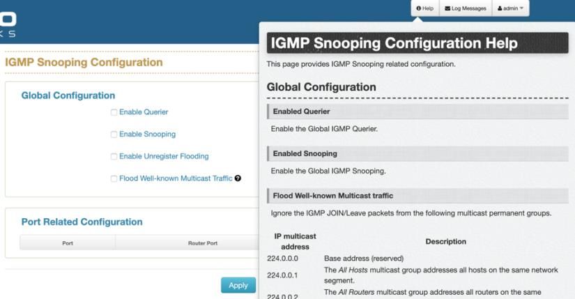
Important Notice

Optigo Networks, Inc. reserves the right to modify the equipment, its specification or this
manual without prior notice, in the interest of improving performance, reliability, or
servicing. At the time of publication all data is correct for the operation of the equipment
at the voltage and/or temperature referred to.
Performance data indicates typical values related to the particular product.

No part of this documentation or information supplied may be divulged to any third party
without the express written consent of Optigo Networks Inc. Products offered may
contain software which is proprietary to Optigo Networks Inc. The offer or supply of
these products and services does not include or infer any transfer of ownership.

Applied Models

This user manual applies to Optigo Networks’ ONS-C801pi and ONS-C1601pi industrial
managed edge switches.

The model list may be changed, Optigo Networks, Inc. reserves the right to modify the
equipment, its specification or this manual without prior notice

                                             2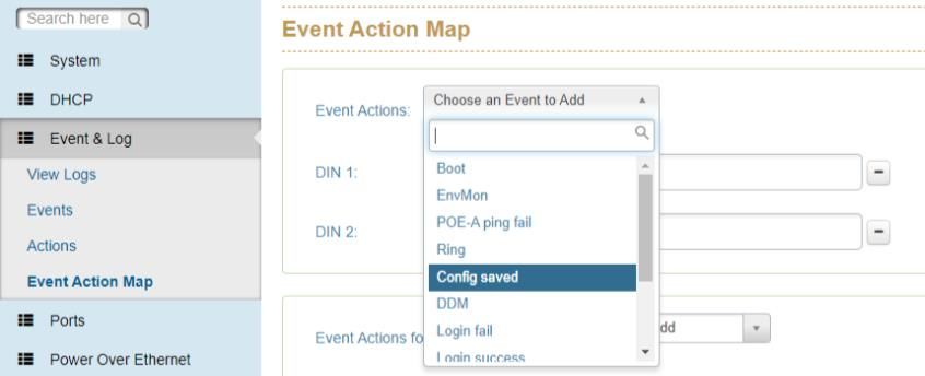
Table of Contents
1. About Web Browser Management .............................................................................. 6
   1.1. Preparing for Web Browser Management....................................................................... 6
   1.2. System Login ..................................................................................................................... 6
   1.3 Introduction to the Web Browser Interface ..................................................................... 8
2. System ............................................................................................................................ 9
   2.1 System Configuration ...................................................................................................... 10
   2.2 System Information .......................................................................................................... 11
   2.3 IP Configuration ................................................................................................................ 12
   2.4 System Time ...................................................................................................................... 12
   2.5 User Accounts................................................................................................................... 15
   2.6 SNMP Configuration ......................................................................................................... 15
       2.6.1 Community................................................................................................................................ 16
       2.6.2 Trap ............................................................................................................................................ 16
       2.6.3 V3 Users .................................................................................................................................... 17
   2.7 Fault Relay Configuration ................................................................................................ 17
   2.8 Digital Input / Digital Output (DIDO) ............................................................................... 18
   2.9 System Environment Monitoring .................................................................................... 19
3. DHCP ............................................................................................................................. 20
   3.1 Basic DHCP Server ........................................................................................................... 20
   3.2 MAC-based DHCP ............................................................................................................. 21
   3.3 DHCP Option66 ................................................................................................................. 21
   3.4 DHCP Option82 ................................................................................................................. 22
   3.5 Port-based DHCP .............................................................................................................. 22
   3.6 DHCP Status ...................................................................................................................... 23
   3.7 DHCP Snooping ................................................................................................................ 23
4. Event & Log .................................................................................................................. 24
   4.1 View Logs .......................................................................................................................... 24
   4.2 Events ................................................................................................................................ 25
   4.3 Actions ............................................................................................................................... 26
       4.3.1 Local Log Action ...................................................................................................................... 26
       4.3.2 Remote Syslog ......................................................................................................................... 26
       4.3.3 Email Action.............................................................................................................................. 27
       4.3.4 SNMP Trap Actions .................................................................................................................. 28
       4.3.5 DOut Action .............................................................................................................................. 29
   4.4 Event Action Map.............................................................................................................. 30
5. Ports .............................................................................................................................. 33

                                                                              3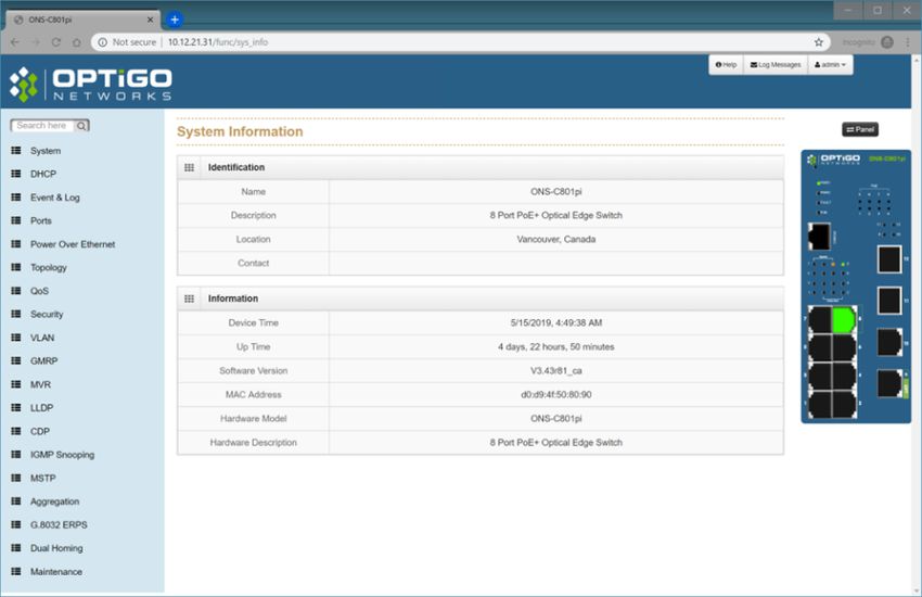
5.1 Configuration .................................................................................................................... 33
   5.2 Status ................................................................................................................................. 34
   5.3 Statistics ............................................................................................................................ 35
   5.4 IEC Packet Statistics ........................................................................................................ 35
   5.5 Mirroring ............................................................................................................................ 36
   5.6 Rate Limiting ..................................................................................................................... 36
   5.7 Loop Protection ................................................................................................................ 38
6. Power over Ethernet ................................................................................................... 39
   6.1 Configuration .................................................................................................................... 40
   6.2 Status ................................................................................................................................. 40
   6.3 Detection ............................................................................................................................ 41
   6.4 Scheduling ......................................................................................................................... 42
7. Topology ....................................................................................................................... 44
8. QoS ................................................................................................................................ 45
9. Security ......................................................................................................................... 48
   9.1 MAC Address Tables ........................................................................................................ 48
       9.1.1 Static MAC Address ................................................................................................................. 48
       9.1.2 MAC Filtering ............................................................................................................................ 49
       9.1.3 All MAC Addresses .................................................................................................................. 49
   9.2 Access Control List .......................................................................................................... 50
   9.3 IEEE 802.1X (Radius Server) ........................................................................................... 51
   9.4 IP Security ......................................................................................................................... 51
10. VLAN ........................................................................................................................... 53
   10.1 Operation Mode .............................................................................................................. 54
   10.2 Port-based VLAN Config................................................................................................ 54
   10.3 802.1Q VLAN Config ....................................................................................................... 55
   10.4 802.1Q VLAN Status ....................................................................................................... 56
11. Multicast VLAN Registration (MVR) ........................................................................ 57
12. LLDP............................................................................................................................ 58
   12.1 LLDP Configuration ........................................................................................................ 58
   12.2 LLDP Neighbor Information........................................................................................... 59
   12.3 LLDP Statistics ............................................................................................................... 60
13. Cisco Discovery Protocol (CDP) ............................................................................. 61
   13.1 CDP Configuration Device Settings ............................................................................. 62
   13.2 CDP Status ...................................................................................................................... 62

                                                                           4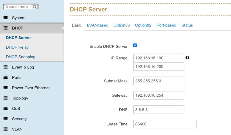
13.2.1 Statistics ................................................................................................................................. 63
      13.2.2 Neighbors................................................................................................................................ 63
14. IGMP Snooping .......................................................................................................... 64
   14.1 IGMP Snooping Configuration ...................................................................................... 64
      14.1.1 Global Configuration ............................................................................................................. 65
      14.1.2 Port-Related Configuration ................................................................................................... 65
   14.2 IGMP Snooping Status ................................................................................................... 66
      14.2.1 Statistics ................................................................................................................................. 66
      14.2.2 IGMP Groups .......................................................................................................................... 67
   14.3 Router Port Status .......................................................................................................... 67
15. MSTP ........................................................................................................................... 68
   15.1 MSTP Global Configuration ........................................................................................... 69
   15.2 CIST Settings................................................................................................................... 70
      15.2.1 Bridge Configuration ............................................................................................................. 70
      15.2.2 Port Configuration ................................................................................................................. 70
      15.2.3 How to enable STP/RSTP ...................................................................................................... 71
      15.2.4 How to enable MSTP .............................................................................................................. 71
   15.3 MSTP MSTI Settings ....................................................................................................... 72
   15.4 MSTP Bridges Status ..................................................................................................... 72
   15.5 Bridge Status of all Ports............................................................................................... 73
16. Link Aggregation ....................................................................................................... 74
   16.1 Aggregation Configuration ............................................................................................ 74
   16.2 LACP Group Status ........................................................................................................ 75
17. G.8032 ERPS .............................................................................................................. 76
   17.1 Configuration .................................................................................................................. 76
   17.2 Status ............................................................................................................................... 76
18. Dual Homing .............................................................................................................. 78
   18.1 Configuration .................................................................................................................. 78
   18.2 Status ............................................................................................................................... 78
19. Maintenance ............................................................................................................... 79
   19.1 Save Configuration ......................................................................................................... 79
   19.2 Config Backup/Restore .................................................................................................. 79
   19.3 Restart Device (Maintenance Reboot) .......................................................................... 80
   19.4 Firmware Upgrade .......................................................................................................... 80
   19.5 Diagnostics...................................................................................................................... 81
      19.5.1 Ping .......................................................................................................................................... 81
      19.5.2 ARP Table ............................................................................................................................... 81
      19.5.3 DDM ......................................................................................................................................... 82

                                                                             5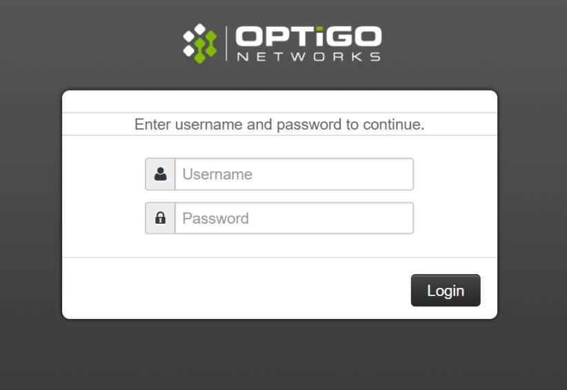
1. About Web Browser Management
There is a web browser interface on the switch, which offers advanced management
features and allows users to manage the switch from anywhere on the network through
the latest version of Google’s Chrome web browser.
Optigo’s ONS-C801pi and ONS-C1601pi switches are designed to be managed using
Optigo OneView™. However, they can also be managed directly, as standalone devices,
via their web browser interface.

1.1. Preparing for Web Browser Management

Before managing your industrial switch via the web browser interface, connect it to the
network with its management port (ONS-C801pi → port 8 / ONS-C1601pi → port 16) and
make sure that one of the PCs on that network can connect to it through the web browser.
If this switch was previously managed using Optigo’s OneView™, reset it to defaults first
by holding down the recessed reset button on the front for 30 seconds.

The switch’s default management IP address, subnet mask, username and password are
listed as below:
           ▪ IP Address: 192.168.255.254

          ▪   Subnet Mask: 255.255.255.0

          ▪   Default Gateway: 192.168.255.1

          ▪   User Name: admin

          ▪   Password: 0pt1goat (ZERO-pt-ONE-goat)

If the switch’s management IP has not yet been configured (e.g. via the CLI), configure
your PC with an IP address of 192.168.255.100, but with the same Subnet mask and
Default Gateway as listed above, and then connect your PC’s Ethernet port directly to the
switch’s management port. You can revert your PC’s network settings back to the way
they were once the switch’s network settings have been configured.

1.2. System Login
   1. Launch Chrome web browser on the computer.

   2. Type in http:// followed by the IP address of the switch, and then Press “Enter”.

                                               6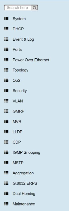
3. The login screen will appear immediately after.

4. Log in with the default credentials (see previous page).

5. Press “Enter” or click the Login Button, and the home screen of the management
   interface will appear.

6. The switch also supports SSL login, so if you need SSL to protect your switch’s access
   account, please type in https:// followed by the IP address of the switch, and then press
   “Enter”.

   NOTE: The changes you make in the dialogs will be written to the device when you click
   “Apply”, but in order for these settings to be retained after power cycling or rebooting the
   switch, you must save them first by going to “Admin” and selecting “Save Configs”.

                                            7
1.3 Introduction to the Web Browser Interface
From the left menu, left-click on the function you want to modify.
82. System
The “System” submenu consists of the following:
• System Configuration
• System Information
• IP Configuration
• System Time
• User Accounts
• SNMP Configuration
• Fault Relay Alarm
• Digital Input/Output
• Environmental Monitoring
92.1 System Configuration
This section displays the system parameters of the device:
• The system name
• The system description
• The system location
• The name of the contact person for this device
• The value of auto logout time in minutes
Name Description
➊ Name This is description of the switch and can’t be edited manually.
➋ Description Enter a description of the switch, up to 255 characters long
(alphanumeric only).
➌ Location Enter the physical location of the switch (e.g. city name, telephone
closet, 3rd floor, etc.), up to 255 characters long (alphanumeric only).
➍ Contact Enter the contact information (e.g. name and phone number) for the
person who is responsible for the switch, up to 255 characters long
(alphanumeric only)
➎ Auto Logout Enter the duration of user inactivity (in minutes) before the web
Time server ends the session. Choose ‘0’ to disable auto logout.
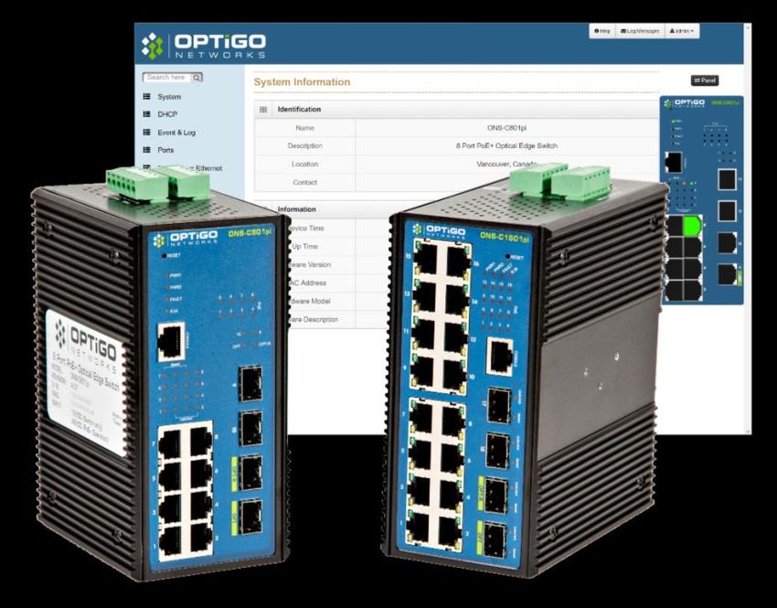
102.2 System Information
This page displays the switch’s basic information.
Identification
Name Description
➊ Name This is the system name of the switch.
➋ Description This is the switch’s description.
➌ Location This is the switch’s geographical location.
➍ Contact This is the contact information for the switch.
Information
Name Description
➎ Device Time This is the time on the switch’s system clock.
➏ Up Time This is the amount of time that has elapsed since the switch
was last powered up or restarted.
➐ Software Version This is the version information for the firmware that’s currently
installed on the switch.
➑ MAC Address This is the switch’s unique Media Access Control address.
➒ Hardware Model This is the switch’s model name.
➓ Hardware This is a description of the switch, containing some basic info
Description about it.
112.3 IP Configuration
The IP settings include the switch’s management IP address and subnet mask, as well
as the IP address of the default gateway and the DHCP client status.
Name Description
➊ DHCP Client Set the switch as a DHCP client to get the IP address from a
DHCP server (unchecked → static IP).
➋ IP Address Input the IP address of the switch (IPV4).
➌ IPV6 Address Input the IP address of the switch (IPV6), if applicable.
➍ Network Mask Input the network mask of the IP address.
➎ Default Gateway Input the address of the network gateway (e.g. router address).
➏ DNS Server IP If you need the switch to enable internet service (like SNTP),
please input the correct address for the DNS server.
2.4 System Time
Network Time Protocol (NTP) is a networking protocol for clock synchronization
between computer systems over packet-switched, variable-latency data networks. NTP
is intended to synchronize all participating computers to within a few milliseconds of
Coordinated Universal Time (UTC). It uses the intersection algorithm, to select accurate
time servers and is designed to mitigate the effects of variable network latency. NTP
can usually maintain time to within tens of milliseconds over the public Internet and can
achieve better than one millisecond accuracy in local area networks under ideal
conditions. Asymmetric routes and network congestion can cause errors of 100 ms or
more.
12Note: This section is taken from the Wiki at
https://en.wikipedia.org/wiki/Network_Time_Protocol
Name Description
➊ Time Zone Universal Time Coordinated. Set the switch location time zone. The
following table lists the different location time zone for your reference.
Options Default Settings
Please refer to “Table: Location None
Time Zone” on the next page.
➋ Clock You can set the time of the switch manually or set SNTP server to let
Source the switch synch the time with SNTP server via internet.
Options Default Settings
Manual SNTP
SNTP
➌ SNTP The IP address of the SNTP server.
Manual Mode: If the switch can’t access the internet due to security considerations, you
can manually set the switch’s clock by pressing “Get Browser Time”. The system time of
the switch will then be synchronized with your PC via Chrome web browser.
Note: For the most accurate system time synchronization, only use network
components (i.e. routers, switches, hubs) which support SNTP in the signal path
between the SNTP server and the SNTP client.
13Table: Location Time Zone
Local Time Zone Conversion from UTC Time at 12:00 UTC
November Time Zone -1 Hour 11 am
Oscar Time Zone -2 Hours 10 am
ADT – Atlantic Daylight -3 Hours 9 am
AST – Atlantic Standard -4 Hours 8 am
EDT – Eastern Daylight
EST- Eastern Standard -5 Hours 7 am
CDT – Central Daylight
CST – Central Standard -6 Hours 6 am
MDT – Mountain Daylight
MST – Mountain Standard -7 Hours 5 am
PDT – Pacific Daylight
PST – Pacific Standard -8 Hours 4 am
AKDT – Alaskan Daylight
AKST – Alaskan Standard -9 Hours 3 am
HST – Hawaiian Standard -10 Hours 2 am
CET – Central European +1 Hour 1 pm
FWT – French Winter
MET – Middle European
SWT – Swedish Winter
EET – Eastern European +2 Hours 2 pm
USSR Zone 1
AST – Arabia Standard Time +3 Hours 3 pm
USSR Zone 2
ZP4 – USSR Zone 3 +4 Hours 4 pm
ZP5 – USSR Zone 4 +5 Hours 5 pm
ZP6 – USSR Zone 5 +6 Hours 6 pm
AWST – West Australian Standard +8 Hours 8 pm
CST – China Standard +8 Hours 8 pm
USSR Zone 7
JST – Japan Standard +9 Hours 9 pm
14USSR Zone 8
AEST – East Australian Standard +10 Hours 10 pm
ChST – Chamorro Standard (Guam)
USSR Zone 9
IDLE – International Date Line +12 Hours Midnight
NZT – New Zealand
2.5 User Accounts
This dialog gives you the option of changing the read and read/write passwords that are
required for device access. Please note that passwords are case sensitive. Set different
passwords for read and read/write privileges.
Name Description
➊ Password: Enter the password for each account.
➋ New User: Click the ‘New User’ button to add new account.
➌ Permission: Set the permission level of each account.
Options Default Setting
Read-Write, Read-Only Read-Write
2.6 SNMP Configuration
The ONS-C801pi and ONS-C1601pi both support SNMP V1, V2c, and V3. SNMP V1 and
SNMP V2c use a community string match for authentication in which the SNMP servers
access all objects with read-only or read/write permissions using the community strings
public and private by default. SNMP V3 requires you to select an authentication level of
MD5 or SHA, which is the most secure protocol. You can also enable data encryption for
enhanced security.
152.6.1 Community
Name Description
➊ Agent Version: Detected by system automatically.
Option Default Setting
V1 / V2c / V3 Detected by
system
automatically
➋ String: Set the community string of SNMP protocol with read only
permission or read/write permission.
2.6.2 Trap
Name Description
➊ IP Address Enter the IP address of the trap destination (e.g. the PC of the
IT manager).
➋ String Enter the community string of the SNMP trap.
➌ Version Select the SNMP trap version.
Options Default Setting
V1 V2c
V2c
162.6.3 V3 Users
Name Description
➊ User Name Set the user name.
➋ Security Level Set up the access level. The default is ‘NoAuth, NoPriv”.
➌ Authentication Protocol Set the authentication type, the default value is ‘N/A’.
➍ Authentication Set the authentication password, the default value is
Password ‘N/A’.
➎ Privacy Protocol Set the privacy protocol, the default value is ‘N/A’.
➏ Privacy Password Set the privacy password, the default value is ‘N/A’.
Note: For security reasons, SNMPv3 encrypts the password. With the “SNMPv1” or
“SNMPv2” setting in the dialog, Security: SNMPv1/v2 access, the switch transfers the
password unencrypted, meaning it will be shown and readable.
2.7 Fault Relay Configuration
This section allows you to set the conditions (e.g. power failure, port link status, etc.)
required to trigger the switch’s Alarm Relay. The alarm relay terminal pins are the
middle two pins on the green terminal blocks.
17Name Description
➊ Power Failure If you check ‘Power 1’ and ‘Power 2’ in a redundantly powered
system, the alarm will be triggered if power is lost on either input.
➋ Port Link Choose which port(s) will trigger the alarm relay if their connection
Down/Broken fails.
2.8 Digital Input / Digital Output (DIDO)
The switch contains two digital input pins, as well as two digital output pins. When
enabled, the digital inputs detect transitions in electrical signals (e.g. when a connected
device powers off), while the digital outputs allow the switch to output electrical signals
to an external device (e.g. provide a signal to a relay).
Digital Input: When First/Second Digital Input function is enabled, First Digital
Input/Second Digital Input will then be available respectively. Digital Input: Choose the
transition type to trigger DI0/DI1.
Name Description
➊ Low → High Having focused this radio button, DI0/DI1 will only report the status
when the external device's voltage changes from low to high.
➋ High → Low Having focused this radio button, DI0/DI1 will only report the status
when the external device's voltage changes from high to low.
➌ Event Please fill in the description for the event.
Description
18Digital Output: When First/Second Digital Output function is enabled, First Digital
Output/Second Digital Output will then be available respectively.
Name Description
➊ Action Choose the output type of electrical signal.
➋ Low → High Having focused this radio button, DO0/DO1 will output an electrical
signal of Low-to-High when the condition of the ticked checkbox is
met (port/power failure occurs).
➌ High → Low Having focused this radio button, DO0/DO1 will output an electrical
signal of Low-to-High when the condition of the ticked checkbox is
met (port/power failure occurs).
2.9 System Environment Monitoring
This page displays basic information on the system’s current condition, including CPU
and memory usage. However, temperature monitoring is not currently supported.
193. DHCP
This section contains the dialogs, displays, and tables for:
• DHCP Server
• DHCP Relay
• DHCP Snooping
3.1 Basic DHCP Server
Name Description
➊ Enable DHCP Server Enable the switch’s DHCP server (See note below).
➋ IP Range Define the IP range to be assigned to DHCP clients.
➌ Subnet Mask Define the Subnet Mask to be assigned to DHCP clients.
➍ Gateway Define the gateway address to be assigned to DHCP
clients.
➎ DNS Define the DNS address to be assigned to DHCP clients.
➏ Lease Time Define the DHCP clients’ lease time.
20Note:
Enable DHCP Client: This enables the switch to receive its IP address from a DHCP
server. The switch is then considered to be a DHCP client of that DHCP server.
Enable DHCP Server: This enables the switch to act as a DHCP server and issue IP
addresses to other devices. The switch is then considered to be a DHCP server, and
then the other devices are DHCP clients.
* Before the DHCP Server can be enabled, DHCP client must be disabled. This is
because devices cannot be a server and a client simultaneously. Therefore, the
switch must have a static IP address manually assigned to it.
3.2 MAC-based DHCP
Assign specific IP addresses to clients with specific MAC addresses. This is also known
as DHCP reservation by MAC address.
Name Description
➊ MAC Address Enter the MAC address of the device you want to assign a
specific IP address.
➋ IP Address Enter the IP address that you want to assign to that device.
3.3 DHCP Option66
Assign a dedicated IP address of a TFTP server under the DHCP option66 standard.
Name Description
➊ Server Enter the IP address of the TFTP server.
213.4 DHCP Option82
Assign a dedicated IP address under the DHCP option82 standard; you need to assign
one Optigo switch as an option82 server and another Optigo switch as a DHCP relay.
Name Description
➊ Remote ID Enter the ID of a remote DHCP option82 relay switch.
➋ Circuit ID Enter the port ID of a remote DHCP option82 relay switch.
➌ IP Range Enter the IP address range that will be assigned via the current ID.
➍ Netmask Assign the netmask.
➎ Gateway Assign the gateway address.
➏ DNS Assign the DNS address.
➐ Lease Time Enter the DHCP lease time for the IP address (in seconds).
3.5 Port-based DHCP
Assign dedicated IP address by port that is connected to the device.
Name Description
➊ Port No. The switch port number connected to the device.
➋ Desired IP Enter the dedicated IP address to be assigned to this port.
➌ Do not offer IP Disable the assignment of IP addresses to the end device.
223.6 DHCP Status
This will show you what IP address have been assigned to the clients.
Name Description
➊ Port No. The switch port number.
➋ MAC Address The MAC address of the end device.
➌ IP Address The IP address of the end device.
➍ Name The host name of end device.
➎ Available Leased Time The remaining DHCP lease time.
3.7 DHCP Snooping
Configure a dedicated port to forward DHCP packets or block malicious DHCP traffic.
Name Description
➊ Enable DHCP Snooping Enable the DHCP snooping function.
➋ Port No. The switch port number.
➌ Mode Trusted: This port will forward DHCP packets.
Untrusted: This port will block DHCP packets.
Options Default Setting
Trusted Untrusted
Untrusted
234. Event & Log
The Event & Log section displays the following information:
• View Logs
• Events
• Actions
• Event Action Map
4.1 View Logs
This section shows the system log entry including the following action types:
Name Description
➊ Login User Login.
➋ Boot System Boot.
➌ DDM DDM information from SFP module.
24➍ DIN Digital Input Event triggered status.
➎ Link Change Port link up or down.
➏ POE POE Status.
➐ Power Power status.
➑ Ring Configuration Change or Save
Note: The maximum log size is 1000 entries. When the log exceeds this size, it will
delete the oldest entry.
4.2 Events
This section will help you to monitor the status of SFP Digital Diagnostic Monitor events.
(“Environmental monitoring Event” is currently not supported).
You can set the trigger range of each SFP DDM event.
Name Description
➊ Temperature Working temperature of SFP.
➋ Voltage Working voltage of SFP.
➌ TX Bias Bias of SFP.
➍ TX Power Tx power of SFP.
➎ RX Power Rx power of SFP.
Note: This function only works for SFP modules with the DDM spec.
254.3 Actions
When the switch detects an event, it will trigger one of the pre-configured actions below:
• Local Log Action
• Remote Syslog Action
• Email Action
• SNMP Trap Actions
• DOUT Action
4.3.1 Local Log Action
Name Description
➊ Save to Local Enable saving of the log to the local switch.
4.3.2 Remote Syslog
The “Syslog” dialog enables you to also send events to one or more syslog servers
locally or remotely. You can enable or disable this with the check box.
26Name Description
➊ Log to Remote Syslog Server Enable to save log to a remote Syslog Server.
➋ Syslog Server Enter the IP address of the remote Syslog server.
➌ Tag Tag the event to categorize events into groups.
➍ Facility This is the machine process that logged the event.
➎ Host Name Name of the Syslog Server, e.g. Sys-Ser-3.
4.3.3 Email Action
Name Description
➊ Email Alert Enable log alerts to be sent out via email.
➋ Subject Enter the subject of the alert email (e.g. link down).
➌ Sender The email address of the email account used for email
notifications.
➍ SMTP Server The address of the SMTP server.
➎ Server Port The email server port.
➏ User ID Login for the sender’s email account (not the entire email address).
➐ Password The password for the sender’s email account (Gmail™ may require
an app password).
➑ Enable SSL Check if using Secured Socket Layer (very common).
➒ Receivers Enter the email address(es) of the alert recipient(s).
274.3.4 SNMP Trap Actions
Clicking the ‘SNMP Trap Action” Link will bring you to the following page.
Name Description
SNMP Trap Action The user is redirected to the ‘SNMP Trap’ configuration, with a
direct link to that page.
Here we can configure the SNMP manager; here we can see an example of an SNMP
manager configured named Optigo.
Name Description
➊ IP Address Set the IP address of the SNMP Manager.
➋ Community Set the name of the “community” that will use this SNMP Manager.
➌ Version Specify what version of software is on the SNMP Manager.
284.3.5 DOut Action
Name Description
DOut Action The user is redirected to the ‘Digital Input/Output’ configuration,
with a direct link to that page.
Here we can configure the Digital Input and Digital Output Actions.
• A digital signal can be high or low (making a binary 0 or 1). We can create
actions based on changes from high to low.
• In the screenshot (above) we can see Digital Input 1 has been set to have an
action of Low → High. Digital Input 2 is disabled.
Name Description Options Default Setting
➊ DIN1 Digital Input 1 LOW → HIGH None
HIGH → LOW
➋ DIN2 Digital Input 2 LOW → HIGH None
HIGH → LOW
➌ DOUT1 Digital Output 1 LOW → HIGH None
HIGH → LOW
➍ DOUT2 Digital Output 2 LOW → HIGH None
HIGH → LOW
294.4 Event Action Map
You can combine event and action settings here. The two actions selected in the
screenshot are Digital Input 1 and Digital Input 2.
➊
Name Description
➊ Event Action Which event will be combined with the desired action.
Event Actions: Please follow the steps below to set the event actions.
A: Choose the event which you want to activate.
Name Description Options Default Setting
➊ Event Actions Which event will be Boot None
combined with the EnvMon
desired action. POE-A ping fail
Ring
Config Saved
DDM
Login fail
Login success
Power1 on
Power1 off
Power2 on
Power2
30B: The selected event will be shown as follows. In the screenshot, the events
‘Config Saved’, ‘Login Success’ and ‘Login Fail’ have been added. Choose your
preferred method to forward this event to the manager side.
Name Description Options Default Setting
➊ Selected Event Which action will be Email None
combined with this SMS
event. SNMP Trap
DOUT 1
DOUT 2
Event Actions for Link Change:
Please follow the steps below to set the event actions:
A: Choose the Port (Link) and Event you want to activate.
Name Description Options Default Setting
➊Selected Event Which action will be Selected Port UP None
combined with this Selected Port DOWN
port and event.
31B: The selected event will be shown as follows. In the screenshot, the events
‘Port 1 UP’, ‘Port 3 UP’, ‘Port 4 DOWN’, ‘Port 5 UP’ and ‘Port 5 DOWN’ have
been added. Choose your preferred method to forward this event to the manager
side.
Name Description Options Default Setting
➊ Port Event Which action will be Email None
combined with this Syslog
event DOUT 1
DOUT 2
325. Ports
This section will show you how to control and manage the switch’s ports.
5.1 Configuration
Port settings are displayed and can be modified on the Device Settings panel.
Name Description
➊ Port No. The port number.
➋ Type Port type (100Tx/1000T/GSFP/DSFP).
➌ Description Enter up to 47 alphanumeric characters to describe the port.
➍ Enabled Enable traffic on the port.
➎ Flow Control Enable flow control.
➏ Speed Select the speed of the port from supported options.
Options Default Setting
Disabled: Deactivate the port Auto
33Auto: Let’s the port negotiate the speed
with the device it’s connected to and reach
the maximum speed that is possible.
10Mbps HDX: Forces the cu port to
10Mbps half duplex mode.
10Mbps FDX: Forces the cu port to
10Mbps full duplex mode.
100Mbps HDX: Forces the cu port to
100Mbps half duplex mode.
100Mbps FDX: Forces the cu port to
100Mbps full duplex mode.
1Gbps FDX: Forces the cu port to 1Gbps
full duplex mode
5.2 Status
Name Description
➊ Port No Port number.
➋ Type Port type (100TX/1000T/GSFP/DSFP).
➌ Link Link status: up or down.
➍ State Port state: enabled or disabled.
➎ Speed The port’s link speed, which is the capability of the currently
connected device (N/A if nothing is connected).
➏ Flow Control Flow control status.
Note: Flow Control is only available when the port’s speed is set to
‘Auto’ and therefore it’s efficiency is subject to the negotiation
between the port and the device it’s connected to.
345.3 Statistics
Name Description
➊ Port Number of each port.
➋ Type Media type of each port (100TX/1000T/GSFP/DSFP).
➌ Link Link status: Up or Down.
➍ State Port status.
➎ Tx Good The number of good packets sent out of this port.
➏ Tx Bad The number of bad packets sent out of this port.
This includes: undersized (less than 64 octets], oversized, CRC
alignment errors, fragments, and jabber packets).
➐ Rx Good The number of good packets received by this port.
➑ Rx Bad The number of bad packets received by this port.
This includes: undersized (less than 64 octets], oversized, CRC
alignment errors, fragments, and jabber packets).
➒ Tx Abort The number of packets that were aborted during transmission.
➓ Collision The number of packet collisions.
⓫ Drop The number of packets dropped.
⓬ RX BCAST The number of broadcast packets received by this port.
⓭ RX MCAST The number of multicast packets received by this port.
⓮ TX MCAST The number of multicast packets sent out of this port.
5.4 IEC Packet Statistics
355.5 Mirroring
Port Mirroring can be used to monitor network traffic. With port mirroring enabled, the
switch sends a copy of all network packets seen on selected ports (Source Port) to
another port (Destination Port), where the packets can be analyzed (e.g. by one of
Optigo’s BACnet Capture Tools).
Source Port: All of a source port’s selected traffic (Rx, Tx, or both) will be copied to the
Destination Port.
Destination Port: Only a single port can be configured as the Destination Port and all
of the source ports’ selected traffic will be copied to it.
Name Description
➊ Direction Both Tx and Rx traffic can be monitored on Source Ports.
➋ Destination Port Choose the port that will be the mirror port, the one that will
receive a copy of the selected traffic (Rx, TX or both) from all
monitored ports.
➌ Source Port(s) Select which ports will be monitored by choosing them in the
appropriate row. If you want to monitor both Tx and Rx traffic on
a particular port, simply choose that port in both rows.
5.6 Rate Limiting
Limiting allows the user to set a limit for each port's ingress/egress data rate.
Ingress control supports data rate limiting and packet type limiting (All, Unicast,
Multicast and Broadcast).
36Egress control only supports data rate limiting.
Name Description
➊ Packet Select which packet types should be rate-limited.
Type All the ports support port ingress and egress rate control. For example,
assuming port 1 is rated at 10Mbps, users can set its effective egress
rate to 1Mbps and its ingress rate to 500Kbps. The switch references
the packet counter value to enforce the specified rate.
Packet Types Default Setting
All All
Unicast
Multicast
Broadcast
➋ Ingress Enter the ingress rate limit (The default value is "0").
➌ Egress Enter the egress rate limit (The default value is "0").
Note: Rate Limiting works exclusively on layer 2 to limit the impact of flooding packets.
Therefore, this function ignores any protocol information present in higher layers (e.g.
IP, TCP, etc).
Note: Ports that are included in a Link Aggregation are excluded from the rate limitation,
regardless of the entries in the “Rate Limiting” dialog
375.7 Loop Protection
Loop Protection helps to prevent the broadcast storms that are generated when a loop
is created in your network.
Name Description
➊ Enable Loop Protection Enable or disable loop protection.
➋ Interval (seconds) Define how often the switch will check the loop status of
each port.
➌ Shutdown (seconds) Define how long the port will be blocked when it is
looping.
Name Description
➊ Looping Displays the loop status of the port.
➋ Loop Counts Displays how many loops have occurred at the port.
➌ Last Loop at Displays the last time that a loop occurred at the port.
386. Power over Ethernet
Power over Ethernet (PoE) is a way to transmit power over Ethernet cable to PD
(Powered devices). The standards are IEEE 802.3at/af with different power output. The
IEEE802.3af can transmit max 15.4W per port while IEEE802.3at, also known as PoE+,
transmit 30W per port. In the physical connection of PoE technology, please consider
power loss over the length of cable. The minimum power available is 12.95 Watts per
port over IEEE802.3af and 25.5Watts per port over IEEE802.3at standard.
There are several common techniques for transmitting power over Ethernet cabling.
Two of them have been standardized by IEEE 802.3 since 2003. These standards are
known as Alternative A and Alternative B. For 10BASE-T and 100BASE-TX, only two of
the four data/signal pairs in typical CAT-5 cable are used. Alternative B separates the
data and the power conductors, making troubleshooting easier. It also makes full use of
all four twisted pair, copper wires. The positive voltage runs along pins 4 and 5, and the
negative along pins 7 and 8.
Note: This part is taken from the Wiki at
https://en.wikipedia.org/wiki/Power_over_Ethernet
Optigo supports most PoE switches as PSE (power sourcing equipment) using
Alternative A technique. Only a couple of models support Alternative B technique.
Optigo PoE models have options with different input ranges including 12/24V 48V
boost up, 72V 48V step down and high voltage 85~265VAC/ 110~300VDC.
Furthermore, Optigo managed PoE switches offer PD detection and PoE scheduling for
advanced PoE management.
396.1 Configuration
➋
Name Description
➊ Maximum Power Available Set the maximum total power consumption (W).
➋ Legacy Mode Force the switch to supply power to legacy PD.
➌ Port No. The PoE port number.
➍ Enabled Enable or Disable the port’s PoE functionality.
➎ Scheduling Set the PoE port to be controlled with the PoE
scheduling function.
➏ Priority Set the power supply priority. If the total power
consumption of all PoE ports exceeds the maximum
power limit, then the switch will supply power by
priority setting.
Priority Options Default Setting
Low / High / Critical Low
➐ Power Limit Define the maximum power supplied by the PoE port
(mW).
6.2 Status
System
40Name Description
➊ Power Consumption This is the total power consumption of all PoE ports.
➋ Main Voltage This is the output voltage of each PoE port.
➌ Main Current This is the output current of each PoE port.
Ports
Name Description
➊ Port No. The PoE port number.
➋ Link The connection status of each PoE port.
➌ State The PoE status of each connected PD (Unknown means that
the connected device is non-PD.
➍ Temperature (℃) The temperature of the PoE chipset.
➎ Current (A) The output current of each PoE port.
➏ Power (W) The power consumption of each PoE port.
➐ Determined Class The PoE class of each connected PD.
6.3 Detection
41Name Description
➊ No. The PoE port number.
➋ Enabled Enable of Disable PoE detection.
➌ IP address The IP address of the connected PD (Powered Device).
➍ Interval Define how often to ping the connected PD.
➎ Retry Time Define how many ping failures are allowed before the PD is
considered as failed (min = 1, max = 5).
➏ Failure Log The record of PD detection failures.
➐ Failure Action The action to be taken when a PD fails.
Action Default Setting
Nothing: No action. Nothing
Power Down: Shut down power on PoE port.
Power On: Keep PoE port powered ON.
Restart Forever: Continuously power cycle the
PoE port.
Restart Once: Reset the PoE port just once.
➑ Reboot Time If the action is set to ‘Restart Forever’, then Reboot Time defines
the time between restarts (min = 3 secs, max = 120 secs).
6.4 Scheduling
42Set the weekly PoE power-on schedule.
In this example (see screenshot above), the PD is set to power on at 10:00 am on
Sunday, and then power off again one hour later, at 11:00 am.
437. Topology
The Topology feature is currently not supported.
448. QoS
Quality of service (QoS) is the description or measurement of the overall performance of
a service, such as a telephony or computer network or a Cloud computing service,
particularly the performance seen by the users of the network. To quantitatively
measure quality of service, several related aspects of the network service are often
considered, such as error rates, bit rate, throughput, transmission delay, availability,
jitter, etc.
In the field of computer networking and other packet-switched telecommunication
networks, quality of service refers to traffic prioritization and resource reservation control
mechanisms rather than the achieved service quality. Quality of service is the ability to
provide different priority to different applications, users, or data flows, or to guarantee a
certain level of performance to a data flow.
Quality of service is particularly important for the transport of traffic with special
requirements. In particular, developers have introduced technology to allow computer
networks to become as useful as telephone networks for audio conversations, as well
as supporting new applications with even stricter service demands.
Note: This section is taken from the Wiki at
https://en.wikipedia.org/wiki/Quality_of_service
QoS Policy: Optigo’s ONS-C801pi/ONS-C1601pi switches have multiple traffic queues
that allow packet prioritization to occur. Higher priority traffic can pass through the
switch without being delayed by lower priority traffic. As each packet arrives, it is
processed and then sorted into the appropriate queue. The switch then forwards
packets from each queue.
Optigo’s ONS-C801pi/ONS-C1601pi switches support two different queuing
mechanisms:
• Weighted Fair Queue Ratio: This method services all the traffic queues, giving
priority to the higher priority queues. Under most circumstances, the Weighted
Fair Queue Ratio gives high priority precedence over low priority, but in the event
that high priority traffic does not reach the link capacity, lower priority traffic is
allowed, though.
45• Strict: This method services high traffic queues; low priority queues are delayed
until no more high priority data needs to be sent. The Strict method always gives
precedence to high priority over low priority.
Name Description
➊ Use the weighted fair The switch will follow 8:7:6:5:4:3:2:1 rate to process
queuing scheme priority queue from the Highest to lowest queue.
➋ Priority Type Port-base: the port priority will follow the default port
priority that you have assigned - high, center, low, or
lowest.
CoS: the port priority will only follow the CoS priority that
you have assigned.
ToS only: the port priority will only follow the ToS priority
that you have assigned.
ToS first: the port priority will follow the ToS priority first,
and then the other priority rule.
Port-based: Set the priority of traffic per port.
VLAN: Set the priority of traffic by VLAN.
46➍
Name Description
➊ CoS Set the CoS priority level (0 to 7).
➋ ToS Only System provides 0~63 ToS Priority level.
➌ ToS First System provides 0~63 ToS priority level. Each level has 8 types of
priority - 0~7. The default value is "1" priority for each level. When
the IP packet is received, the system will check the ToS level value
in the IP packet it has received. For example, the user sets the ToS
level 25 is 7. The port 1 is following the ToS priority policy only.
When the packet received by port 1, the system will check the ToS
value of the received IP packet. If the ToS value of received IP
packet is 25 (priority = 7), and then the packet priority
will have highest priority.
➍ Port Based Define the priority by switch port.
➎ VLAN Based Define the priority by VLAN tag.
479. Security
The “Security” menu contains the dialogs, displays, and tables for configuring the
security settings:
• MAC Address Table
• Access Control List
• IEE Security 802.1X (Radius Server)
• IP Security
9.1 MAC Address Tables
Use the MAC address table to manage port security.
9.1.1 Static MAC Address
You can add a static MAC address, which will remain in the switch’s MAC address
table, regardless of whether the device is physically connected to the switch or not. This
saves the switch from having to re-learn a device’s MAC address if it is disconnected or
powered off. You can add, modify, or delete a static MAC address.
48Name Description
➊ MAC Address Enter the MAC address of the device that is allowed on the
specified port.
➋ VLAN ID Enter the corresponding VLAN ID.
➌ Port No. Specify the port by selecting it from the drop-down list.
➍+ Add a new entry to the table of static MAC addresses.
9.1.2 MAC Filtering
MAC Filtering helps to filter pre-configured MAC addresses, which enhances safety.
You can add and delete MAC addresses from the list to be filtered.
Name Description
➊ MAC Address Enter the MAC address to be filtered.
➋ VLAN ID Enter the corresponding VLAN ID.
9.1.3 All MAC Addresses
This panel shows the source MAC address and its corresponding port for all of the
packets passing through.
Name Description
➊ VLAN ID Displays the VLAN ID.
➋ Type Dynamic or Static.
49➌ MAC The MAC address of a connected device or other network
Address equipment.
➍ Port This is the port corresponding to the MAC address.
9.2 Access Control List
This Access Control List (ACL) can be used to deny access to devices with specific IP
addresses or MAC addresses.
Name Description
➊ Index The index number of the ACL rule.
➋ Ingress/Egress Select whether to apply the ACL rule to Ingress of Egress traffic.
Options Default Setting
Ingress Ingress
Egress
➌ Direction Apply the ACL rule to either the Source or the Destination
address of the packets.
Options Default Settings
Source Destination
Destination
➍ Type Apply the ACL rule to either the IP address or the MAC address
of the packets.
Options Default Setting
IP IP
MAC
➎ Address Set the address (MAC or IP) to be processed by the ACL rule.
50➏ Mask Set the Subnet Mask.
➐ Action Select the action to be taken by the ACL rule.
Actions Default Setting
Deny Permit
Permit
9.3 IEEE 802.1X (Radius Server)
IEEE 802.1X defines a protocol for client/server-based access control and
authentication. The protocol restricts unauthorized clients from connecting to a LAN
through ports that are open to the Internet, and which otherwise would be readily
accessible. The purpose of the authentication server is to check each client that
requests access to the port. The client is only allowed access to the port if the client’s
permission is authenticated.
9.4 IP Security
The IP security function allows users to assign 20 specific IP addresses that have
permission to access the switch through the web browser for switch management.
51Name Description
➊ Web Check this option to make web access available for switch
management.
➋ Telnet Check this option to make Telnet access available for switch
management.
➌ SSH Check this option to make SSH access available for switch
management.
➍ Admin Access Following the IP list should be allowed or denied with
Restriction Policy web/Telnet/SSH access.
Options Default Setting
Allow All Allow All
Deny All
➎ IPs/Ranges Assign up to 20 specific IP addresses to be allowed or denied
access to the admin service(s).
5210. VLAN
A virtual LAN (VLAN) is any broadcast domain that is partitioned and isolated in a
computer network at the data link layer (OSI layer 2). LAN is the abbreviation for local
area network and in this context ‘virtual’ refers to a physical object recreated and altered
by additional logic. VLANs work through tags within network packets and tag handling in
networking systems - recreating the appearance and functionality of network traffic that
is physically on a single network but acts as if it is split between separate networks. In
this way, VLANs can keep networks separate despite being connected to the same
network, and without requiring multiple sets of cabling and networking devices to be
deployed.
VLANs allow network administrators to group hosts together, even if the hosts are not
on the same network switch. This can greatly simplify network design and deployment,
because VLAN membership can be configured through software. Without VLANs,
grouping hosts according to their resource needs necessitates the labor of relocating
nodes or rewiring data links. It also has benefits in allowing networks and devices that
must be kept separate to share the same physical cabling without interacting, for
reasons of simplicity, security, traffic management, or economy. For example, a VLAN
could be used to separate traffic within a business for different users or between types
of traffic, so that users or low priority traffic cannot directly affect the rest of the network.
Many Internet hosting services use VLANs to separate their customers' private zones
from each other, allowing each customer's servers to be grouped together in a single
network segment while being located anywhere in their datacenter. Some precautions
are needed to prevent traffic "escaping" from a given VLAN, an exploit known as VLAN
hopping.
The VLAN membership configuration for the switch can be monitored and modified
here. Up to 4094 VLANs are supported. This panel allows for adding and deleting
VLANs as well as adding and deleting port members of each VLAN.
Note: This section is taken from the Wiki at https://en.wikipedia.org/wiki/Virtual_LAN
53You can also read