Trusted Internet Connections - (TIC) 3.0 Design Guide April, 2021 - Cisco
←
→
Page content transcription
If your browser does not render page correctly, please read the page content below
Architecture Guide
                                                                                 Cisco Public

          Trusted Internet Connections
                    (TIC) 3.0
                                                           Design Guide

                                                             April, 2021

© 2021 Cisco and/or its affiliates. All rights reserved.                          Page 1 of 70
Contents
Overview                                                             3
Design Guide                                                         4
   Branch                                                            5
       Direct Cloud Access (DCA)                                     5
           Firewall                                                15

           Intrusion Prevention                                    16

           URL Filtering                                           18

           Advanced Malware Protection (AMP)                       18

           DNS Security                                            18

           TLS/SSL Decryption                                      18

           Adding the policy to the network                        19

       Direct Internet Access (DIA)                                20
       Enabling TIC Security Capabilities                          26
           AMP Clouds                                              27

           Dynamic Analysis Cloud                                  27

   Remote User                                                     32
       FTD Remote Access VPN                                       32
           Static Split Tunnel                                     39

           Dynamic Split Tunnel                                    41

       Duo Multi-Factor Authentication                             45
       Cisco AnyConnect Client Profile                             51
       Cisco Endpoint Security Analytics (CESA)                    53
       Cisco Cloudlock                                             59

© 2021 Cisco and/or its affiliates. All rights reserved.   Page 2 of 70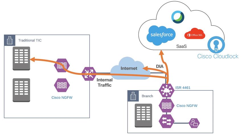
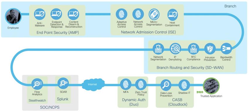
Overview

Figure 1.
TIC 3.0 architecture

Cisco’s security approach for TIC 3.0 is not only designed to fulfill the requirements of distributed PEPs in the
agency network but is also designed to fit with the relationships between TIC and other federal initiatives such
as Continuous Diagnostics and Mitigations (CDM) and the National Institute of Standards and Technology (NIST)
Zero trust Architecture. Zero Trust is a security model that shifts the access conversation from traditional
perimeter-based security and instead focuses on secure access to applications based on user identity, the
trustworthiness of their device and the security policies you set, as opposed to the network from where access
originates. Zero Trust models assume that an attacker is present on the network and that an enterprise-owned
network infrastructure is no different. Zero Trust Architecture (ZTA) focuses on three elements in the network,
regardless of their location, securing the workforce, securing the workplace, and securing the workloads.

The guiding principles of ZTA resonate with the Universal capabilities outlined by TIC. For example:

     ●    Developing, documenting, and maintaining a current inventory of all systems, networks, and components
          so that only authorized devices are given access.
     ●    Least privilege for each entity on the network.
     ●    Verifying the identity of users. Devices, or other entities through rigorous means such as MFA before
          granting access.
     ●    Constantly monitoring the network for vulnerabilities and staying up to date with the latest and greatest
          Threat Intelligence.

© 2021 Cisco and/or its affiliates. All rights reserved.                                                    Page 3 of 70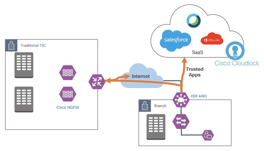
TIC 3.0 offers agencies the freedom to implement a more flexible TIC model. It is common for agencies to
utilize cloud services and accommodate remote workers’ need access to all agency resources. These changes
also impact the attack surface of the Federal Government. Instead of a singular location for policy enforcement,
TIC 3.0 allows for distributing enforcement to different locations along the path if the deployed protections
maintain a commensurate level of protection based on the agency’s risk tolerance. This document is an
extension to the TIC 3.0 Architecture Guide and will detail deployment steps for securing remote users and
branch offices as per the guidance shown in that document.

Design Guide
Software Version used in this guide

 Location                                                  Product                              Version

 Data Center                                               vManage                              20.3.1

 Data Center                                               vSmart                               20.3.1

 Data Center                                               vBond                                20.3.1

 Data Center                                               Firepower Management Center (FMC)    6.6

 Data Center                                               Splunk Enterprise                    8.1.0

 Data Center                                               CESA                                 3.7.1

 Data Center                                               Cisco NVM Flow collector             3.7.1

 Data Center                                               Cisco AnyConnect profile editor(s)   4.8

 Branch                                                    ISR4461                              IOS-XE 17.2

 Branch                                                    FTD 1010                             6.6

 Cloud                                                     Duo

 Cloud                                                     AMP & ThreatGrid

 Cloud                                                     Cloudlock

 Endpoint                                                  AnyConnect Secure Mobility Client    4.9

© 2021 Cisco and/or its affiliates. All rights reserved.                                                      Page 4 of 70
Branch
In this deployment a private SD-WAN environment consisting of vManage, vBond, vSmart and a single ISR-
4461 were used following the procedure in the Cisco SD-WAN End-to-End Deployment Guide.

Direct Cloud Access (DCA)

Figure 2.
Enabling DCA in Cisco SD-WAN

This guide offers two options for Branch security. The first option is to enable DCA with the native firewall of a
Cisco IOS XE SD-WAN device sitting at the edge of the branch. The firewall capabilities in the Cisco IOS XE
SD-WAN can apply enforcement up to and including layer 7 (applications) and is managed using the same
vManage dashboard that was used to create the SD-WAN overlay. For more details on this deployment see
Cisco SD-WAN: Enabling Direct Internet Access.
Pre-requisites
     ●    The SD-WAN controllers are set up and deployed (vManage, vBond, vSmart)
     ●    A router has been configured using device templates in order to establish a functional and secure
          overlay fabric to pass data traffic across the organizations distributed sites. An SD-WAN Deployment
          guide can be found here.
     ●    Upload a Security Virtual Image to vManage. For an installation guide see Security Virtual Image.

© 2021 Cisco and/or its affiliates. All rights reserved.                                                      Page 5 of 70
Application Routing

Application routing in the Cisco SD-WAN platform can be achieved using a couple of different methods. For
simplicity, and since this guide mainly focuses on security, applications will be configured to always take the
direct path. The alternate method is to configure Application-Aware routes which choose the optimum path
based on the Service Level Agreement (SLA) of each route. For more information see Cisco SD-WAN:
Application-Aware Routing Deployment Guide.
Procedure 1. Verify the SD-WAN vSmart controller is in vManage mode.
Step 1.          In vManage, navigate to Configuration > Devices and select Controllers. If controller is in
                 vManage mode, continue to the next procedure, otherwise continue to follow the steps.

Step 2.          If the vSmart is in CLI mode, a device template must be configured and attached to vSmart.
                 Highlight vSmart and click on Change Mode > vManage mode.

Step 3.          Click Template.

© 2021 Cisco and/or its affiliates. All rights reserved.                                                       Page 6 of 70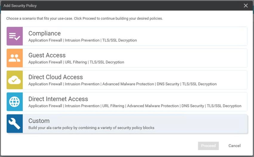
Step 4.          Click Create Template > CLI Template.

Step 5.          In the Device Model dropdown, choose vSmart. Add a meaningful name to the Template
                 Name and Description. In the Load Running config from reachable device dropdown, choose
                 the vSmart device. This loads the current CLI configuration from the device.

Step 6.          Click Add.
Step 7.          On the newly created vSmart device template, click the ellipses and choose Attach Devices.

© 2021 Cisco and/or its affiliates. All rights reserved.                                                 Page 7 of 70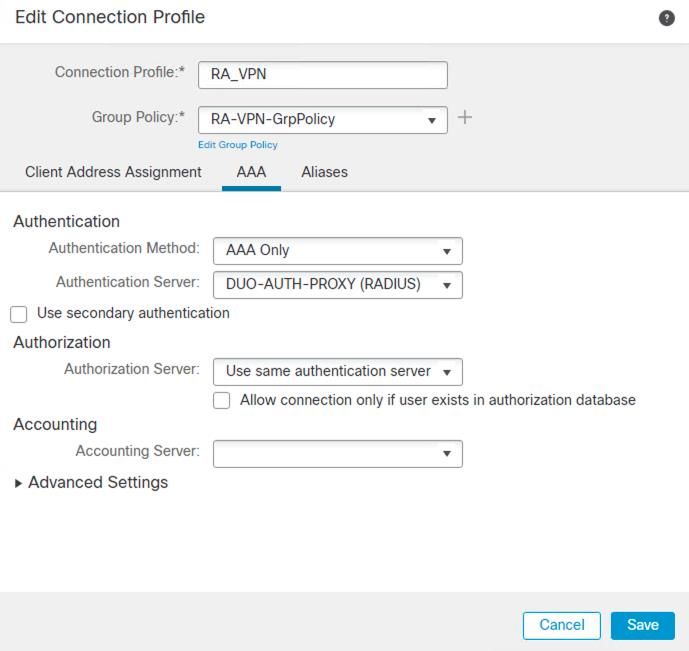
Step 8.          Choose the vSmart device and click Attach.
Step 9.          Click on the vSmart device on the left-hand panel, double check the configuration and click
                 Configure Devices.
Step 10.         Once complete, navigate back to Configuration > Devices and select Controllers. The device
                 will now be in vManage mode.

Procedure 2. Configuring the Routing policy
Step 1.          In vManage, navigate to Configuration > Policies.

Step 2.          Under Centralized Policy, click + Add Policy.

© 2021 Cisco and/or its affiliates. All rights reserved.                                                       Page 8 of 70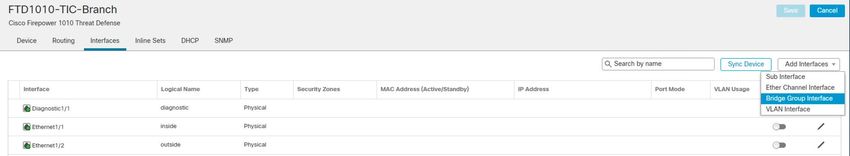
Step 3.          The first task is to create an application list that your agency would like to break from the
                 tunnel. This example will show Office365 and WebEx. In the Application tab, click + New
                 Application List.

Step 4.          Give a meaningful name to the policy and with the Application radio button selected, search and
                 click Microsoft Office 365 and WebEx. Click Add.

Step 5.          In the Site tab, click + New Site List.
Step 6.          This is where we define which sites this policy will apply to. Add a meaningful name to the site list
                 and add all site id’s that this DCA policy will apply to. This example used only a single branch so
                 only a single site was added. When all sites have been added, click Add.

Step 7.          In the VPN tab, click + New VPN List.
Step 8.          Give a meaningful name to the VPN list and all VPNs that this rule applies to. Click Add.

© 2021 Cisco and/or its affiliates. All rights reserved.                                                         Page 9 of 70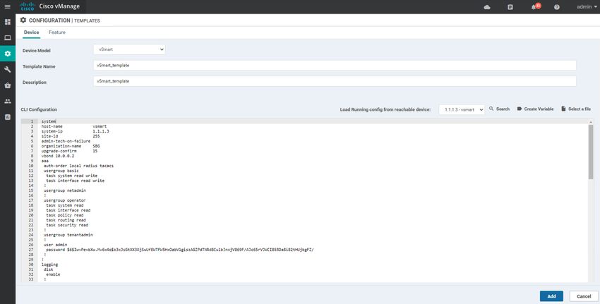
Step 9.          Click Next until you get to the Configure Traffic Rules tab.
Step 10.         In the Traffic Data tab, click + Add Policy > Create New.

Step 11.         Add a Name and Description.
Step 12.         By default, all traffic is dropped. To change this, click the pencil icon and click Accept. Click Save
                 Match and Actions. In this example, default routes were learned through BGP and therefore
                 accepting all traffic in this policy will send traffic to these default routes. An alternate approach to
                 BGP would be to configure the default routes in this policy and to re-order the application routes
                 accordingly.

© 2021 Cisco and/or its affiliates. All rights reserved.                                                        Page 10 of 70
Step 13. Click + Sequence Type.
Step 14. Choose Traffic Engineering.
Step 15. Click + Sequence Rule.
Step 16. In the Match tab, click Application/Application Family List and choose the application list
previously created.
© 2021 Cisco and/or its affiliates. All rights reserved. Page 11 of 70Step 17. For this example, a static route was used to directly connect to the cloud. For more routing options,
such as using a TLOC, see Cisco SD-WAN Design Guide. In the Actions tab, click Next Hop and
provide the next hop route for direct cloud connectivity. Click Save Match and Actions.
Step 18. Click Save Data Policy.
Step 19. Click Next.
Step 20. Provide a Policy Name and Policy Description.
Step 21. In the Traffic Data tab, click + New Site List and VPN List and add the previously created Site List
and VPN List.
Step 22. Click Save Policy.
Step 23. This action should take you to the Configuration > Policies screen. Click the ellipses in the newly
defined policy and click Activate.
© 2021 Cisco and/or its affiliates. All rights reserved. Page 12 of 70Step 24. A popup will appear. Click Activate. SD-WAN Security policies The purpose of this guide is to show the user the security options available in the device(s), not necessarily the recommended deployment policies as this will be highly dependent on the environment. Each procedure shown here will provide an example configuration that maps to a TIC security requirement. It is the responsibility of the user to decide how these policies are implemented in their network. Figure 3. Secure access to trusted applications with required capabilities In the TIC 3.0 Architecture Guide a reduced set of security capabilities were outlined for DCA traffic. As all untrusted web traffic is being backhauled to the Traditional TIC, and only trusted traffic is split from the tunnel, a smaller subset of security capabilities are necessary. Nevertheless, the SD-WAN security stack does have more features that won’t be configured here such as Break and Inspect and URL filtering. Later in this guide, additional security measures will be implemented in the Branch using a Cisco Secure Firewall device. For a full Direct Internet Access guide using Cisco SD-WAN and a Secure Internet Gateway, see Cisco SD-WAN Secure Direct Internet Access. © 2021 Cisco and/or its affiliates. All rights reserved. Page 13 of 70
Step 1.          In vManage, navigate to Configuration > Security.

Step 2.          Click + Add Security Policy.
Step 3.          vManage provides multiple pre-set policy combinations, depending on the level of security you
                 require at the branch. In this guide we will choose Custom. Not all features in Custom will be
                 needed for the recommended deployment, however, links will be provided for more information on
                 each to allow customization options in your agency.

© 2021 Cisco and/or its affiliates. All rights reserved.                                               Page 14 of 70
Firewall
The Firewall policy configuration can be used to meet the requirements for IP Blacklisting, Content Filtering,
Domain Category Filtering and Network Segmentation. For a full SD-WAN firewall policy guide see Enterprise
Firewall with Application Awareness.
Step 1. Click + Add Firewall Policy > Create New.
Step 2. Add a Name and Description.
Step 3. Change Default Action to Pass.
Step 4. Network Segmentation. At the top of the page, click Apply Zone-Pairs. This feature allows you to
define firewall policies for incoming and outgoing traffic between a self-zone of an edge router and
another zone. When a self-zone is configured with another zone, the traffic in this zone pair is
filtered as per the applied firewall policy.
Step 5. In the Source Zone field, choose the zone that is the source of the data packets.
Step 6. In the Destination Zone field, choose the zone that is the destination of the data packets.
Step 7. Optional: Click the + icon to create a zone pair.
Step 8. Click Save.
© 2021 Cisco and/or its affiliates. All rights reserved. Page 15 of 70Step 9. Click + Add Rule.
Step 10. Choose if this policy will Pass, Drop or Inspect the traffic in the Action drop down menu.
Step 11. IP Denylisting. In the Source Data Prefix column, add the IP range that this rule applies. In the
Destination Data Prefix column, add the IP range that this rule applies. Blocking traffic from a
source network is used to stop devices from sending traffic through the firewall. Applying Denylists
at the Destination network ensures hosts don’t reach devices or servers at a specified IP address.
Step 12. Content Filtering, Domain Category Filter. In the Application List to Drop column, add the
Applications that should be dropped when this rule is triggered. To add a new application list, click
+ Application List to Drop and then click + New Application List. The chosen applications can be
individual, such as Facebook, or based on category, such as gaming.
Step 13. Click Save.
Step 14. Click Save Firewall Policy.
Step 15. At the bottom of the page, click Next.
Intrusion Prevention
© 2021 Cisco and/or its affiliates. All rights reserved. Page 16 of 70The Intrusion Prevention policy configuration can be used to meet the requirements for Intrusion Prevention
and Malicious Content Filtering. For a full SD-WAN Intrusion Prevention policy guide see Intrusion Prevention
System.
Note: Please upload compatible Security App Hosting Image File to the software repository in order to
support IPS functions. You can upload the image file in vManage from Maintenance > Software
Repository > Virtual Images.
Step 1. Click + Add Intrusion Prevention Policy > Create New.
Step 2. Click + Target VPNs. Add VPNs that this policy applies to and Save.
Step 3. Add a Policy Name.
Step 4. When choosing a Signature Set there are three options:
● Connectivity – Enables signatures with a CVSS score of 10 and CVE published within last 2 years.
● Balanced – Enables signatures with a CVSS score >= 9 and CVE published within last 2 years. Includes
rule categories Malware CNC, Exploit Kits, SQL Injection and Denylist.
● Security – Enables signatures with a CVSS score >= 8 and CVE published within last 3 years. Included
rules categories Malware CNC, Exploit Kits, SQL Injection, Denylist and App Detect Rules.
© 2021 Cisco and/or its affiliates. All rights reserved. Page 17 of 70Step 5. In the Inspection Mode dropdown choose either Detection (alert only) or Protection (alert and
block) depending on agency needs.
Step 6. Click Save Intrusion Prevention Policy.
Step 7. Click Next.
URL Filtering
The URL filtering policy configuration can be used to meet the requirement for Domain Category and
Reputation Filtering. In this example deployment, all web traffic, with the exception of Office365 and WebEx,
are backhauled to a Traditional TIC where URL filtering policies will be applied and centrally managed. To apply
URL Filtering policies at the branch, see URL Filtering.
Advanced Malware Protection (AMP)
The AMP policy can be used to meet the requirements for Anti-Malware, Content Disarm, Detonation
Chamber, Content Filtering and Malicious Content Filtering. AMP is composed of three processes:
● File Reputation - The process of using a 256-bit Secure Hash Algorithm (SHA256) signature to compare
the file against the AMP cloud server and access its threat intelligence information. The response can be
Clean, Unknown, or Malicious. If the response is Unknown, and if File Analysis is configured, the file is
automatically submitted for further analysis.
● File Analysis - The process of submitting an Unknown file to the Threat Grid (TG) cloud for detonation in
a sandbox environment. During detonation, the sandbox captures artifacts and observes behaviors of the
file, then gives the file an overall score. Based on the observations and score, Threat Grid may change
the threat response to Clean or Malicious. Threat Grid’s findings are reported back to the AMP cloud, so
that all AMP customers will be protected against newly discovered malware.
● Retrospective - By maintaining information about files even after they are downloaded, we can report
on files that were determined to be malicious after they were downloaded. The disposition of the files
could change based on the new threat intelligence gained by the AMP cloud. This re-classification will
generate automatic retrospective notifications.
For details on adding AMP and TG to an SD-WAN security policy see Advanced Malware Protection.
DNS Security
The DNS Security policy can be used to meet the requirements for DNS Sinkholing, DNNSEC and NCPS E3A
DNS Protections. Configuring the DNS policy configures the router to act as a DNS forwarder on the network
edge, transparently intercepts DNS traffic, and forwards the DNS queries to a specified location. For a full SD-
WAN DNS Security policy guide see Cisco Umbrella Integration.
TLS/SSL Decryption
© 2021 Cisco and/or its affiliates. All rights reserved. Page 18 of 70The TLS/SSL Decryption policy can be used to meet the requirements for Break and Inspect and Certificate
Denylisting. Decrypting and re-encrypting traffic is a resource intensive capability and has been deemed out of
scope for this particular use case. According to Microsoft “Most enterprise networks enforce network security
for Internet traffic using technologies like proxies, SSL inspection, packet inspection, and data loss prevention
systems. These technologies provide important risk mitigation for generic Internet requests but can dramatically
reduce performance, scalability, and the quality of end user experience when applied to Microsoft 365
endpoints”. In the DCA use case, we only break trusted applications off from the tunnel, and therefore mitigate
the need to do TLS decryption on this traffic. Extra protections can be added in the cloud such as a CASB for
visibility into the application itself, and TLS decryption can be reserved for unknown or untrusted web traffic. If
your agency has a requirement to do SSL decryption at the branch, a full SD-WAN TLS/SSL Decryption guide
can be found at SSL/TLS Proxy.
Adding the policy to the network
Step 1. In the Policy Summary tab, add a Security Policy Name and Description. Click Save Policy.
Step 2. In vManage, navigate to Configuration > Templates.
Step 3. Click the ellipses on the device template that this policy applies to and click Edit.
Step 4. In the Additional Templates section, click on the Security Policy dropdown list and choose the
newly created policy.
Step 5. Click Update and push the policy to the device(s).
Cisco TrustSec
Cisco TrustSec is an end-to-end network infrastructure that provides a scalable architecture for the
enforcement of role-based access control, identity-aware networking, and data confidentiality to secure the
network and its resources. Cisco TrustSec uses Security Group Tags (SGT) to represent user and device
groups. The switches, routers, and firewalls inspect these tags and enforce SGT-based traffic policies.
Cisco TrustSec is defined in three phases: classification, propagation, and enforcement. After traffic is
classified, the SGT is propagated from where Classification took place, to where enforcement action is invoked.
This process is called propagation. One of the SGT propagation methods that Cisco TrustSec offers is inline
tagging.
With inline tagging, a special Ethernet frame is used to propagate these SGTs between network hops where the
policies can be enforced based on the SGT policy. Cisco IOS XE SD-WAN devices support propagation of
SGT.
For full details on how to configure SGT enforcement across the WAN network see Cisco TrustSec Integration.
© 2021 Cisco and/or its affiliates. All rights reserved. Page 19 of 70Additional DCA Security Controls
The above configuration primarily focused on configuring the security policies located on networking
infrastructure. In figure 3, where security capabilities were mapped to Cisco products, additional security
products were shown in order to provide end to end protection in the agency’s architecture. These security
controls, namely AMP for endpoints and Cloudlock, will be discussed in the Remote User section.
Direct Internet Access (DIA)
Figure 4.
Cisco SD-WAN Direct Internet Access with Cisco NGFW
The second option involves using a Cisco FTD device in combination with an SD-WAN router. The advantage of
this deployment is the use of FMC to manage firewall policies across the full organization, regardless of
location. The same rules that were created for the datacenter, can be extended to the branches, using the
same management platform.
Pre-requisites
● The SD-WAN controllers are set up and deployed (vManage, vBond, vSmart)
● An FMC has been deployed to manage the firewall
● The FTD device has gone through its initial configuration and has a functioning route to the FMC. The
quick-start guide for the FTD 1010 can be found here
● Necessary licenses have been obtained for the device (more details can be found in the ‘Install FTD
device’ section below)
● A router has been configured using device templates in order to establish a functional and secure
overlay fabric to pass data traffic across the organizations distributed sites. An SD-WAN deployment
guide can be found here.
© 2021 Cisco and/or its affiliates. All rights reserved. Page 20 of 70Install FTD device
Figure 5.
Cisco FTD 1010 in transparent mode
The Cisco Firepower 1010 security appliance is an NGFW desktop product in the Cisco Secure Firewall family
of devices. Hardware installation guidance can be found here. The Cisco Firepower 1010, which the rest of this
guidance will refer to as the FTD (Firepower Threat Defense) device, is the lowest performing in the Secure
Firewall family. For detailed performance specs, such as throughput when all features are enabled, see the
datasheet. If more performance is needed, there are larger appliances in the range.
Procedure 1. Add device to FMC
Step 1. Access the command line interface of the FMC. The easiest method is through the console port.
Step 2. Identify the FMC that will manage this FTD using the command
configure manager add {hostname | IPv4_address | IPv6 address | DONTRESOLVE} reg_key
[nat_id]
Step 3. In FMC, navigate to Devices > Device Management.
Step 4. In the Add drop-down list, choose Device.
Step 5. Enter the following parameters.
● Host – IP address or hostname of the FTD device.
● Display Name – the name FMC will use for display purposes.
● Registration Key – the key that was specified in step 2 above.
© 2021 Cisco and/or its affiliates. All rights reserved. Page 21 of 70● Group – assign to device group if required.
● Access Control Policy – choose an initial policy. Unless you already have a customized policy, you know
you need to use, choose Create new policy, and choose Block All traffic. This will be modified later to
suit the use case.
● Smart Licensing – enable the features you need to deploy. This guide will use features that require all
three licensing options.
◦ Threat – enables intrusion prevention capabilities
◦ URL – enables category-based URL filtering
◦ Malware – enables AMP malware inspection
● Transfer packets – allows the device to transfer packets to the FMC. When events like IPS are triggered,
this option allows the device to send packet data to FMC for inspection.
© 2021 Cisco and/or its affiliates. All rights reserved. Page 22 of 70Procedure 2. Upgrade the FTD device This guide is using Firepower Threat Defense software version 6.6.0. If your device is lower than that it is recommended to upgrade before continuing on to the next steps. Step 1. Download the latest software upgrade image from software.cisco.com. Step 2. In FMC navigate to System Settings > Updates. Step 3. Click Upload Update. Step 4. Click Choose File and upload the file that was downloaded in step 1. Click Upload. © 2021 Cisco and/or its affiliates. All rights reserved. Page 23 of 70
Step 5.          In the updates page (System Settings > Updates), click Push or Stage update on the upgrade
                 package that was uploaded in the previous step. Note: By pushing the update to the device, the
                 amount of downtime is being reduced. As the package is being transferred to the device, the
                 device remains operational. In a new build, this isn’t as critical, but it is a good practice to follow
                 when updating Firepower devices.

Step 6.          Choose the FTD device(s) you wish to update and click Push.

Step 7.          After the update has been successfully pushed, return back to the updates page and click install on
                 the upgrade package that was pushed in the previous step.

Step 8.          Choose the FTD device(s) you wish to update and click Install.
Procedure 3. Create Transparent route
Step 1.          In FMC, navigate to Devices > Device Management. Check the FTD device is in transparent mode.

Step 2.          Click the pencil icon to edit the device.

© 2021 Cisco and/or its affiliates. All rights reserved.                                                      Page 24 of 70
Step 3. While on the Interfaces tab, click Add Interfaces > Bridge Group Interface.
Step 4. On the Interfaces tab choose the two interfaces on the interface that will act as the bump in the
wire from the router. When running in transparent mode, the firewall needs to know which ports are
paired together. Assign a unique Bridge group ID.
Step 5. On the IPv4 tab, assign an IP address to the BridgeGroup.
© 2021 Cisco and/or its affiliates. All rights reserved. Page 25 of 70Step 6. Click OK.
Enabling TIC Security Capabilities
The purpose of this guide is to show the user the configuration options available on the firewall, not necessarily
the recommended deployment policies as this will be highly dependent on the environment. Each procedure
shown here will provide an example configuration that maps to a TIC security requirement. It is the
responsibility of the user to decide how these policies are implemented in their network.
Creating SSL Policies
The SSL policy configuration can be used to meet the requirements for Break & Inspect and Certificate
Denylisting. For a full SSL policy guide see SSL Policies.
If the system detects a TLS/SSL handshake over a TCP connection, it determines whether it can decrypt the
detected traffic. If it cannot, it applies a configured action:
● Block the encrypted traffic
● Block the encrypted traffic and reset the TCP connection
● Not decrypt the encrypted traffic
If the system can decrypt the traffic, it blocks the traffic without further inspection, evaluates undecrypted traffic
with access control, or decrypts it using one of the following methods:
● Decrypt with a known private key. When an external host initiates a TLS/SSL handshake with a server on
your network, the system matches the exchanged server certificate with a server certificate previously
uploaded to the system. It then uses the uploaded private key to decrypt the traffic.
● Decrypt by resigning the server certificate. When a host on your network initiates a TLS/SSL handshake
with an external server, the system resigns the exchanged server certificate with a previously uploaded
certificate authority (CA) certificate. It then uses the uploaded private key to decrypt the traffic.
Note: Set up decrypt rules only if your managed device handles encrypted traffic. Decryption rules
require processing overhead that can impact performance.
Creating DNS Policies
The DNS policy configuration can be used to meet the requirements for DNS Sinkholing and NCPS E3A DNS
Protections. For a full DNS policy guide see DNS Policies.
DNS-based Security Intelligence allows you to block traffic based on the domain name requested by a client,
using a Security Intelligence Block list. Cisco provides domain name intelligence you can use to filter your
traffic; you can also configure custom lists and feeds of domain names tailored to your deployment.
Traffic on a DNS policy Block list is immediately blocked and therefore is not subject to any further inspection—
not for intrusions, exploits, malware, and so on, but also not for network discovery. You can use a Security
Intelligence Do Not Block list to override a Block list and force access control rule evaluation, and,
recommended in passive deployments, you can use a “monitor-only” setting for Security Intelligence filtering.
This allows the system to analyze connections that would have been blocked by a Block list, but also logs the
match to the Block list and generates an end-of-connection Security Intelligence event.
© 2021 Cisco and/or its affiliates. All rights reserved. Page 26 of 70Creating File Policies
The File policy configuration can be used to meet the requirements for Anti-Malware, Content Disarm,
Detonation Chamber, Content Filtering and Malicious Content Filtering. For a full File policy guide see File
Policies and Malware Protection.
To detect and block malware, use file policies. You can also use file policies to detect and control traffic by file
type. Connections to public or private clouds are required in order to protect your network from malware.
AMP Clouds
The AMP cloud is a Cisco-hosted server that uses big data analytics and continuous analysis to provide
intelligence that the system uses to detect and block malware on your network.
The AMP cloud provides dispositions for possible malware detected in network traffic by managed devices, as
well as data updates for local malware analysis and file pre-classification.
If your organization has deployed AMP for Endpoints and configured Firepower to import its data, the system
imports this data from the AMP cloud, including scan records, malware detections, quarantines, and indications
of compromise (IOC).
Cisco offers the following options for obtaining data from the Cisco cloud about known malware threats:
● AMP public cloud - Your Firepower Management Center communicates directly with the public Cisco
cloud.
AMP private cloud - An AMP private cloud is deployed on your network and acts as a compressed, on-
●
premises AMP cloud, as well as an anonymized proxy to connect to the public AMP cloud. For details,
see Cisco AMP Private Cloud. NOTE: If you integrate with AMP for Endpoints, the AMP private cloud
has some limitations. See AMP for Endpoints and AMP Private Cloud.
Dynamic Analysis Cloud
● Cisco Threat Grid cloud - Public cloud that processes eligible files that you send for dynamic analysis
and provides threat scores and dynamic analysis reports.
● On-premises Cisco Threat Grid appliance - If your organization's security policy does not allow the
Firepower System to send files outside of your network, you can deploy an on-premises appliance. This
appliance does not contact the public Cisco Threat Grid cloud. For more information, see Dynamic
Analysis On-Premises Appliance (Cisco Threat Grid).
Creating the Intrusion Policies
The Intrusion policy configuration can be used to meet the requirements for Active Content Mitigation,
Malicious Content Filtering, and Intrusion Protection Systems (IPS). For a full Intrusion prevention policy
guide see Intrusion Policies.
Intrusion policies are defined sets of intrusion detection and prevention configurations that inspect traffic for
security violations and, in inline deployments, can block or alter malicious traffic. Intrusion policies are invoked
by your access control policy and are the system’s last line of defense before traffic is allowed to its
destination.
© 2021 Cisco and/or its affiliates. All rights reserved. Page 27 of 70Create the Access Policy
The access policy configuration is where all of the above functionality comes together for enforcement. In
addition to above access policies can be used to meet the requirements for Content Filtering, DNS-over-
HTTPS Filtering, RFC Compliance Enforcement, Domain Category and Reputation Filtering, Access Control,
IP Denylisting, Network Segmentation, Microsegmentation, NCPS E3A DNS Protections, Adaptive Access
Control and Protections for Data in Transit. For more details on Access Control Policies see Access Control.
Step 1. In FMC, navigate to Policies > Access Control. Click New Policy.
Step 2. File in the required fields:
● Give a meaningful Name.
● Select a Base Policy. For this example, None is chosen, however, if rules have already been created for
another location, and they need to be modified slightly for a new location, it is recommended you choose
that policy and build from that.
● Choose a Default Action. This lab will Block all traffic by default and allow only what is needed.
● Add the relevant device(s) that this policy applies.
Step 3. Click Add Rule.
Step 4. The level of security applied at this point is up to the user. In this lab example, we will build a base
rule that allows most traffic from inside to outside and block all traffic from outside to inside. In the
Zones tab, choose the inside interface as Source and WAN interface as Destination.
© 2021 Cisco and/or its affiliates. All rights reserved. Page 28 of 70Step 5. In the Inspection tab, choose the Balanced Security and Connectivity from the Intrusion Policy
dropdown menu. This enables a predefined set of Intrusion rules to keep users safe from known
threats. For more information on each of the base options see Intrusion Base Policy.
Step 6. In the Logging tab, choose Log at Beginning of Connection.
Step 7. Click Add.
Step 8. For every new rule created, make sure to Insert rule above the base rule created in the previous
step. The firewall will enforce traffic on the first matched rule and therefore there must be no
conflicting rules.
Step 9. Network Segmentation. In the Zones tab, FMC will list all of the Available Zones in the network.
These zones are the names assigned to interfaces on the devices. To segment the network bases
on zones, add relevant zones to the source and destination and choose Allow or Block in the Action
tab, depending on what you are trying to achieve.
Step 10. IP Denylisting. In the Networks tab, network objects can be defined to group IP address’ for use in
access rules. Blocking traffic from a source network is used to stop devices from sending traffic
through the firewall. Applying Denylists at the Destination network ensures hosts don’t reach
devices or servers at a specified IP address.
Step 11. Access Control. Although Access Control is a broad topic, we will focus on identity-based access
control. In the Users tab, policies can be created for a specific group of users, rather than network
objects. FMC gets User information from Microsoft Active Directory. For more information see
Identity Services Engine Passive Identity Connector (ISE-PIC).
© 2021 Cisco and/or its affiliates. All rights reserved. Page 29 of 70Step 12. Content Filtering. In the Applications tab, application detectors can be selected based on category
or alternatively, individual applications can be chosen. Requirements will differ between agencies.
One agency may choose to block all content related to Facebook. This can be achieved by blocking
all traffic assigned to the Facebook application category. Another branch may want to allow
Facebook, but to block Facebook Games. This can be achieved by selecting the individual
application detector for Facebook Games, while leaving the others alone such as Facebook
Comment or Messenger. In the Inspection tab, a File Policy can be selected to limit file content
through the firewall. The File Policy does not have to include malware, it could be a rule that blocks
all files of a particular type, such as .exe.
Step 13. DNS-over-HTTPS Filtering. In the Applications tab, there is an application detector for DNS over
HTTPS. Add this to the list of blocked applications to ensure DNS traffic is not encrypted.
© 2021 Cisco and/or its affiliates. All rights reserved. Page 30 of 70Step 14. Active Content Mitigation. In the Applications tab, there is an application detector for Java. Add
this to the list of blocked applications to block any Java activity from passing the firewall.
Alternatively, monitor the traffic and respond to any unusual activity.
Step 15. Domain Category and Reputation Filtering. In the URLs tab, domains can be blocked based on
category and/or by reputation. For example, your agency may block all Adult traffic with Any
reputation, however, may only block Shopping with Questionable or Untrusted reputation.
Step 16. Intrusion Protection System. In the Inspection tab, choose the Intrusion Policy rules that apply to
the organization. For details on setting custom Intrusion rules, see the section above on Intrusion
Policies.
Step 17. When all access policies have been added and ordered appropriately, make sure to Save and
Deploy.
© 2021 Cisco and/or its affiliates. All rights reserved. Page 31 of 70Remote User
This guide will take you through a sample configuration, specific to the devices used in this lab. More
information on alternate deployments may be found here;
● Remote Access VPNs for Firepower Threat Defense
● Remote Access VPNs for ASA
● Secure Remote Worker Design Guide for AWS
● Secure Remote Worker Design Guide for Azure
FTD Remote Access VPN
Pre-requisites
● FMC is deployed and is managing the FTD device
● A RADIUS server group object exists for primary authentication. For purposes of this design guide, ISE
will be used as the identity store
● Download the latest AnyConnect image files from Cisco Software Download Center
● All devices are appropriately licensed. For more information, see VPN Licensing
● Interfaces should be already configured on targeted devices so that they can be used as a security zone
or interface group to enable VPN access.
For a comprehensive guide to configure Remote Access VPN on Cisco Secure Firewall devices see Remote
Access VPNs for Firepower Threat Defense.
Add Identity Certificate to FTD Device
The example configuration installed a certificate using Self-Signed Enrollment. For other alternatives, such as
using a Trusted Certificate Authority (CA) see Firepower Threat Defense Certificate-Based Authentication.
Step 1. In FMC, navigate to Object > Object Management > PKI > Cert Enrollment.
Step 2. Click Add Cert Enrollment.
© 2021 Cisco and/or its affiliates. All rights reserved. Page 32 of 70Step 3. Add a meaningful Name and optional Description. In the CA Information tab choose Self Signed
Certificate in the Enrollment Type dropdown menu.
Step 4. In the Certificate Parameters tab, specify the certificate contents. NOTE: Common Name (CN) is
mandatory for self-signed certificates in remote access VPN.
Step 5. Optional: Open the Key tab and specify the Key information. For more information click the hyperlink
at start of this section.
Step 6. Optional: Click the Revocation tab and specify the revocation options. For more information click the
hyperlink at start of this section.
Step 7. Click Save.
Step 8. In FMC, navigate to Devices > Certificates.
© 2021 Cisco and/or its affiliates. All rights reserved. Page 33 of 70Step 9. Click Add.
Step 10. Choose the Firepower device that shall be used for remote access in the Device dropdown. Choose
the associated certificate in the Cert Enrollment dropdown.
Step 11. Click Add.
Using the Remote Access VPN Policy Wizard in FMC
Step 1. In FMC, navigate to Devices > VPN > Remote Access.
© 2021 Cisco and/or its affiliates. All rights reserved. Page 34 of 70Step 2. To create a new policy, click Add.
Step 3. Give a meaningful name to the configuration and select the device(s) that will be used for remote
access. Click next.
Step 4. Choose the Authentication Method. This setup uses AAA only as it will also be protected by Duo
MFA in later steps. If running a deployment where MFA does not exist (not recommended), using
certificates is another way for protecting the system from exposed user credentials.
Step 5. Choose the Authentication Server. This guide uses the Duo Authentication Proxy as the
authentication server. See the next section on Duo for configuration options.
© 2021 Cisco and/or its affiliates. All rights reserved. Page 35 of 70Step 6. Assign the IP address pool for VPN users. Click the pencil icon beside IPv4 address pools. Add all
of the address pools that will be assigned to a VPN user on the network. If the address pool has not
already been created, click + and specify the range of addresses that will be assigned to VPN users.
Make sure to give a meaningful name to this address pool. Repeat for IPv6 if desired.
Step 7. Assign a Group Policy. At this stage, we will create a new default policy that will be modified in later
steps of this document. Click + beside the dropdown menu. Assign a meaningful name and click
Save.
Step 8. Click next at bottom of the screen.
Step 9. Upload the latest AnyConnect image both each OS that will connect to the network using the +
button. The VPN gateway can automatically download the latest AnyConnect package to the client
device when the VPN connection is initiated.
© 2021 Cisco and/or its affiliates. All rights reserved. Page 36 of 70Step 10. Tell the policy wizard which interface on the FTD is the outside interface, or in other words, the
interface users will use to connect over VPN.
Step 11. Add the device certificate created in a previous step.
Step 12. Review the configuration before clicking Finish. Note: the subsequent configuration steps will be
detailed in the next part of this document, however, FMC does detail the additional
configuration requirements before the remote VPN will work.
Create Access Policy
Step 1. Navigate to Policies > Access Control > Access Control.
© 2021 Cisco and/or its affiliates. All rights reserved. Page 37 of 70Step 2. Edit the policy attached to the FTD assigned for remote access VPN by clicking the pencil icon.
Step 3. At this stage the policies you assign will be dependent on the security controls that are to be put in
place. For specific functionality that can be applied to the firewall, navigate to the DIA section of the
Branch use case. Since this is a zero-trust deployment model, and we want to follow the principle of
least privilege, we will deny all users by default and then add allow policies on top of that. Click +
Add Rule to create a rule specific to VPN users.
Step 4. Give a meaningful name to the policy. Change the Action to Block.
Step 5. For subsequent rules, in the Networks tab, add the VPN address pool for VPN users into the source
network column. This means that the policy will match to any traffic originating from an IP address
of a VPN user.
Step 6. In the Logging tab, click Log at Beginning of Connection to ensure any attempted connections are
logged.
Step 7. Click Save.
© 2021 Cisco and/or its affiliates. All rights reserved. Page 38 of 70NAT Exemption
SSL will be enabled on port 443. IPsec-IKEv2 uses port 500 and Client Services will be enabled on port 443 for
AnyConnect image download. NAT-Traversal will be enabled by default and will use port 4500. Please ensure
that these ports are not used in NAT Policy or other services before deploying the configuration.
For testing purposes, the FTD was connected directly to a public IP address so a NAT exemption policy was not
needed. For more information visit Configure NAT Exemption.
DNS Policy
To resolve hostname specified in AAA Servers or CA Servers, configure DNS using FlexConfig Policy on the
targeted devices. For testing purposes, all servers were addressed using their IP addresses within a private lab
environment. If your network makes use of domain names, visit Configure DNS.
Split Tunnel
By default, all traffic is sent down the VPN tunnel. This is one of the deployments that is recommended by CISA
for TIC protections, so if that is the desired outcome this becomes an optional step.
Static Split Tunnel
In this example we will create a rule that only sends internal traffic back to the data center. Static split tunneling
is not recommended, but since it’s a quick configuration option we will show its deployment.
Step 1. In FMC, navigate to Object > Object Management > Network.
Step 2. Create a network object using the Add network > Add object dropdown button for each network
range that belongs to the internal network. The example below uses the network range
10.10.0.0/24.
Step 3. If you have created more than one network object, create a network group using the Add network >
Add group dropdown button and add all of the network objects from the previous step.
Step 4. Now that network objects have been created, navigate to Object > Object Management > Access
List > Standard.
Step 5. Click Add Standard Access List.
Step 6. Give a meaningful name to the entry and click Add to add the network group/object from the
previous step.
Step 7. After adding all the network elements, click Save.
© 2021 Cisco and/or its affiliates. All rights reserved. Page 39 of 70Step 8. Navigate to Devices > VPN > Remote Access.
Step 9. Click the pencil icon to edit the remote access vpn configuration that this split tunnel will apply to.
Step 10. Click the pencil icon to edit the remote access vpn connection profile that is used for this
configuration.
Step 11. Click on Edit Group Policy.
Step 12. Navigate to General > Split Tunneling.
Step 13. Under IPv4 Split Tunneling choose Tunnel networks specified below. This is because we will only
send internal traffic through the tunnel. In the dynamic split tunnel configuration, we will do the
opposite, and choose networks not to send down the tunnel.
© 2021 Cisco and/or its affiliates. All rights reserved. Page 40 of 70Step 14. Click Split Tunnel Network List Type > Standard Access List checkbox and select the access list
created in a previous step using the Standard Access List dropdown.
Step 15. Under DNS Request Split Tunneling, choose Always send DNS requests over tunnel unless you
have another means of logging all DNS requests from roaming users (such as using Umbrella DNS
as your DNS resolver).
Step 16. Click Save to save the group policy and then click Save again to save the VPN policy.
Step 17. Deploy all changes that were made so that policies can take effect.
Dynamic Split Tunnel
Dynamic split tunneling is more suitable to TIC since we want to break out trusted internet connections from the
tunnel and typically not based on IP but on domain names. Dynamic split tunneling in FTD is done using
FlexConfigs. Dynamic split tunnel configuration is based on creating a custom AnyConnect attribute of the type
dynamic-split-exclude-domains, then adding that attribute to the group policies used in your RA VPN
connection profiles. For more information, and for configuration options that deviate from this example, see
Advanced AnyConnect VPN Deployments for Firepower Threat Defense with FMC.
Step 1. In FMC, navigate to Object > Object Management > FlexConfig > FlexConfig Object.
Step 2. Click Add FlexConfig Object.
Step 3. Give a meaningful name to the configuration and insert an object body similar to below (this
example shows how to split traffic destined to webex.com and office.com). Keep deployment and
type as default (Once and Append respectively). Note: the description is optional, but if included,
it is not a separate command but part of the anyconnect-custom-attr command. For the domain
names, separate them with a comma but do not include spaces.
© 2021 Cisco and/or its affiliates. All rights reserved. Page 41 of 70webvpn
anyconnect-custom-attr dynamic-split-exclude-domains description traffic for these domains
will not be sent to the VPN headend
anyconnect-custom-data dynamic-split-exclude-domains excludeddomains webex.com,office.com
Step 4. Click Save.
Step 5. Since we are using a custom group policy in our VPN configuration, we are going to reference that
policy within this FlexConfig. On the FlexConfig Objects, click Add FlexConfig Object. Give a
meaningful name to the configuration and insert an object body similar to below (this example
references a group policy called RA-VPN-GrpPolicy). Keep deployment and type as default (Once
and Append respectively).
group-policy RA-VPN-GrpPolicy attributes
anyconnect-custom dynamic-split-exclude-domains value excludeddomains
© 2021 Cisco and/or its affiliates. All rights reserved. Page 42 of 70Step 6. Click Save.
Step 7. Create the FlexConfig object that will deploy the above policies. In FMC, navigate to Devices >
FlexConfig.
Step 8. Click New Policy.
Step 9. Add a meaningful name to the policy and add the FTD device that will be used for remote access.
Click Save.
© 2021 Cisco and/or its affiliates. All rights reserved. Page 43 of 70Step 10. Select the FlexConfig objects previously created from the User Defined column.
Step 11. Use drag and drop to ensure that the objects are in the correct order. Note: The object that creates
the custom attribute object must come before the objects that assign that attribute to the group
policies. Otherwise, if you try to add a custom attribute that does not yet exist, you will get an
error.
Step 12. Click Save.
Step 13. Deploy the changes.
Step 14. To test, connect to the VPN via AnyConnect. In the AnyConnect Statistics Window, navigate to
Connection Information > Dynamic Tunnel Exclusion and a list of all excluded domains will be
shown in the window.
© 2021 Cisco and/or its affiliates. All rights reserved. Page 44 of 70Duo Multi-Factor Authentication
This guide will walk through a single example setup to add second factor authentication to remote access VPN
users. For more details, such as how to deploy to a Cisco ASA device (which isn’t covered in this guide), see
the Duo documentation.
Pre-requisites
● A Duo Admin account
● Duo Authentication Proxy (install steps below) has a route to Duo Cloud, FTD and ISE (or Active Directory
depending on your install)
Add Application to Duo Account
Step 1. In the Duo Admin dashboard, navigate to Applications.
Step 2. Click Protect an Application.
© 2021 Cisco and/or its affiliates. All rights reserved. Page 45 of 70Step 3. Search for Cisco RADIUS VPN and click Protect.
Step 4. Take note of the Integration Key, Secret Key, and API hostname.
Configure Duo User Groups
This setup assumes that users who require access to VPN already have their account details registered to Duo
already. For more information on adding users to Duo see Enroll Users. Included in that redirect link is more
information on importing an existing identity store, such as Active Directory.
Step 1. In Duo, navigate to Groups.
Step 2. Click Add Group.
Step 3. Add a meaningful name to the group and an optional description before clicking Save.
Step 4. Using the + Add User to Group button, add all of the users who require access to the VPN. Click
Save Changes when all users have been added.
© 2021 Cisco and/or its affiliates. All rights reserved. Page 46 of 70Step 5. Navigate to Applications and click on Cisco RADIUS VPN.
Step 6. Scroll down to permitted groups and click the checkbox to Only allow authentication from users
in certain groups. Add the VPN user group that was created in the previous step. This results in
only allowing users who have been added to VPN group, instead of all users who may be registered
to this Duo account for alternate reasons. Click Save.
Configure Duo Authentication Proxy
Step 1. On a windows server (must have a route to the Duo API hostname and must be reachable from the
remote access FTD), install and configure the Duo Application Proxy. All instruction can be found in
the Duo documentation.
The configuration used in this example can be seen below.
[duo_only_client]
[radius_client]
host=$ISE_IP
secret=$ISE_SECRET
[radius_server_auto]
ikey=$DUO_iKEY
skey=$DUO_sKEY
api_host=$DUO_HOST
radius_ip_1=$DUO_RADIUS_IP1
radius_secret_1=$DUO_SECRET1
radius_ip_2=$DUO_RADIUS_IP2
radius_secret_2=$DUO_SECRET2
failmode=safe
client=radius_client
port=1812
© 2021 Cisco and/or its affiliates. All rights reserved. Page 47 of 70Add Duo Authentication Proxy to VPN Configuration
Step 1. In FMC, navigate to Objects > Object Management > RADIUS Server Group.
Step 2. Click Add RADIUS Server Group.
Step 3. Add a meaningful name and add the IP address that the Duo Authentication Proxy can be reached.
Click Save.
© 2021 Cisco and/or its affiliates. All rights reserved. Page 48 of 70Step 4. In FMC, navigate to Devices > VPN > Remote Access.
Step 5. Click the pencil icon to configure the appropriate remote access VPN configuration.
Step 6. Click the pencil icon to configure the appropriate remote access connection profile.
Step 7. In the AAA tab, click the Authentication Server dropdown and choose the Duo Authentication
Proxy RADIUS object. Click Save.
© 2021 Cisco and/or its affiliates. All rights reserved. Page 49 of 70Step 8. Deploy the changes. Test the setup Step 1. Using AnyConnect, type the FQDN/IP Address of the remote access firewall and press Connect. © 2021 Cisco and/or its affiliates. All rights reserved. Page 50 of 70
Step 2.          Enter your username and password.
Step 3.          If the credentials were accepted, a Duo prompt should have been received on the registered device.
                 Accept the connection.

Cisco AnyConnect Client Profile
The AnyConnect package includes modules for a variety of features, such as the AMP enabler, that you can
optionally use to provide additional services to RA VPN connections. Each module includes a profile that you
can edit to make the module work according to your requirements. To enable these modules and profiles on
FTD, you need to use FlexConfig.

© 2021 Cisco and/or its affiliates. All rights reserved.                                                 Page 51 of 70
Create AnyConnect XML Templates
Step 1. Download and install the stand-alone AnyConnect Profile Editor (Windows only). You must also
install Java JRE 6 (or higher) before installing the profile editor. Obtain the AnyConnect profile editor
from software.cisco.com in the AnyConnect Secure Mobility Client category.
Step 2. Use the profile editors to create the profiles you need. For details on each of the AnyConnect
options:
● VPN Profile – Enables the configuration of settings such as always on VPN or managing certificates.
● Network Visibility Module (NVM) – Use this configuration to get visibility into the device that the
AnyConnect module resides on. This will be discussed further in the CESA section below.
● AMP Enabler – Used as a median for deploying AMP for endpoints.
● Umbrella Roaming Security – Provides DNS security when no VPN is active.
Step 3. Each configuration step creates a unique XML file. In a text editor of your choice and using the VPN
profile XML as the master file, combine all modules into a single file. To do this, copy the full XML
configuration from each configure module and place them within the tag.
Step 4. Save the file.
Add Template to VPN Configuration
Step 1. In FMC, navigate to Devices > VPN > Remote Access.
Step 2. Click the pencil icon to edit the remote access VPN configuration that this profile will apply to.
Step 3. Click the pencil icon to edit the remote access VPN connection profile(s) that this configuration
uses.
Step 4. Located directly under the Group Policy dropdown, click Edit Group Policy.
Step 5. In the AnyConnect > Profiles tab, click the add (+) button to add a new Client Profile.
© 2021 Cisco and/or its affiliates. All rights reserved. Page 52 of 70Step 6. Browse for the newly created AnyConnect profile and click Save.
Step 7. Continue to Save until completion. Deploy the configuration.
Step 8. To test, connect to the VPN using AnyConnect.
Step 9. On the device connected via VPN, navigate to About AnyConnect.
Step 10. All modules installed on the device will be listed.
Cisco Endpoint Security Analytics (CESA)
Pre-requisites
● Splunk Account
● For this specific deployment, Splunk Enterprise installed on a 64-bit Linux system.
● Cisco AnyConnect Apex license
● Cisco AnyConnect Profile Editor
© 2021 Cisco and/or its affiliates. All rights reserved. Page 53 of 70Add Apps to Splunk
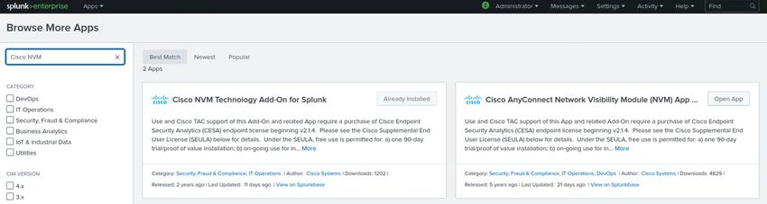
Step 1. In Splunk, navigate to Apps > Find More Apps.
Step 2. Download the following apps:
● Cisco AnyConnect Network Visibility (NVM) App for Splunk - https://splunkbase.splunk.com/app/2992/
● Cisco NVM Add-On for Splunk - https://splunkbase.splunk.com/app/4221/
Install NVM Collector
The Collector Component is responsible for collecting and translating all IPFIX data from the endpoints and
forwarding it to the Splunk Add-on. The NVM collector runs on 64-bit Linux. CentOS, Ubuntu and Docker
configuration scripts are included. The CentOS install scripts and configuration files can also be used in Fedora
and Redhat distributions as well.
In a typical distributed Splunk Enterprise deployment, the collector should be run on either a standalone 64-bit
Linux system or a Splunk Forwarder node running on 64-bit Linux. This guide shows the deployment of an ‘all-
in-one’ configuration running on 64-bit Linux. For more information on additional installation guides see the
CESA installation guide.
Step 1. In the Linux host where Splunk runs, unzip the acnvmcollector.zip file which is located in the
/opt/splunk/etc/apps/$APP_DIR/appserver/addon folder.
© 2021 Cisco and/or its affiliates. All rights reserved. Page 54 of 70You can also read