Setup
Configuration
Technical Guides
←
→
Page content transcription
If your browser does not render page correctly, please read the page content below
Setup Configuration Technical Guides
©2010. All rights are reserved. No portion of this document may be reproduced
without permission. All trademarks and brand names mentioned in this publication
are property of their respective owners.

While all efforts have been made to ensure the accuracy of all contents in this
manual, we assume no liability for errors or omissions or by statements of any kind in
this manual, whether such errors are omissions or statements resulting from
negligence, accidents, or any other cause. The contents of this manual are subject to
change without notice.

This NVR device is intended to be used in a lawful manner. Certain uses of the NVR
device may be prohibited by local laws in some countries of states, such as the
surreptitious recording of audio and/or video communications for certain purposes. If
you have any question about whether a proposed use of your products is lawful, you
should consult a local legal authority before proceeding.

The product is designed and produced to achieve sustainable environmental
improvement. We strive to produce products in compliance with global environmental
standards. Please consult your local authorities for proper disposal. The product
packaging can be recycled.

Attention to recycling (For EU countries only)
Protect your environment! This product should not be thrown into the household
waste container. Please give it to the free collecting center in your community.

The screen shots in this guide were made with Windows XP. If you are using
Windows 7, Vista or 2000, your screens will look somewhat different but functions
are the same.
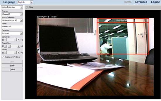
Table of Contents
Introduction.................................................................................................. 1
     How to Use This Guide..........................................................................................1
         Conventions of This Guide..............................................................................1
         A Note about Icons..........................................................................................1
         Safety Precautions ..........................................................................................2
     Main NVR Features ...............................................................................................3
     Minimum System Requirements............................................................................3
     Box Contents .........................................................................................................3
         NVR 4000/4200/4300......................................................................................4
         NVR Slim240...................................................................................................4
         NVR 4200V .....................................................................................................5
     Overview................................................................................................................6
         NVR 4000/4200...............................................................................................6
         NVR 4300........................................................................................................7
         NVR Slim240...................................................................................................8
         NVR 4200V .....................................................................................................9
Chapter I. Setup the NVR ........................................................................... 10
     Setup the NVR System........................................................................................10
         I. Connecting with IP Cameras......................................................................10
         II. Connecting with CCTV Cameras and Video Servers................................14
Chapter II. Working with the NVR ............................................................. 19
     Log in the NVR ....................................................................................................19
         Method I. Network Device Search Tool Application ......................................19
         Method II. IE Address Bar .............................................................................20
     Wizard .................................................................................................................20
         Step 1 – System Settings..............................................................................21
         Step 2 – WAN Settings .................................................................................21
         Step 3 – LAN Settings...................................................................................22
     To Add a New IP Camera....................................................................................23
     NVR Viewer Windows .........................................................................................24
         Language ......................................................................................................24
         Live View.......................................................................................................24
         Record View..................................................................................................26
         Motion Detection ...........................................................................................29
     Log out the NVR ..................................................................................................30
Chapter III. Advanced NVR Configuration ................................................. 31
     Wizard .................................................................................................................31
         Step 1 – System Settings..............................................................................32
         Step 2 – WAN Settings .................................................................................32
         Step 3 – LAN Settings...................................................................................33
     Status ..................................................................................................................34

                                                               i
NVR Status ...................................................................................................34
         IPCam Status ................................................................................................35
     Network ...............................................................................................................35
         WAN..............................................................................................................35
         LAN ...............................................................................................................39
         Client List ......................................................................................................40
     IPCam..................................................................................................................40
         Device Management .....................................................................................41
         Video Settings ...............................................................................................43
     Hard Disk .............................................................................................................45
     System.................................................................................................................45
         Users.............................................................................................................45
         Maintenance..................................................................................................46
         Log ................................................................................................................47
         System Settings ............................................................................................48
         Date & Time ..................................................................................................48
     Database .............................................................................................................49
         Management .................................................................................................49
         Alarm Data Management ..............................................................................50
     Schedule Settings................................................................................................50
         Record Schedule...........................................................................................50
         Event Schedule .............................................................................................51
     Security................................................................................................................52
         Event Settings ...............................................................................................52
         Alarm Notification ..........................................................................................54
         Log ................................................................................................................55
Chapter IV. Technical Guides...................................................................... 56
     LED Indicators .....................................................................................................56
     Search Tool .........................................................................................................56
     IP Configuration Information ................................................................................57
     Use the NVR with Dynamic IP Address...............................................................58
     Proxy Server ........................................................................................................59
     Reset the NVR.....................................................................................................61
     Turn off the NVR..................................................................................................62
Appendix A: Glossary .................................................................................. 63
Appendix B: Specifications ......................................................................... 67
Appendix C: Customer Service and Warranty............................................. 72
     Statement of Limited Warranty ............................................................................72
     FCC Radio Frequency Statement .......................................................................73
Contacting Plustek...................................................................................... 75

                                                              ii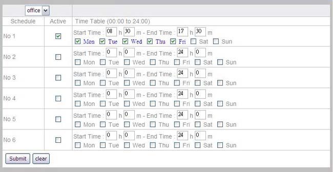
Introduction
Thank you for choosing us as your NVR supplier. Like all of our products, your new
NVR is thoroughly tested and backed by our reputation for unsurpassed
dependability and customer satisfaction. We hope you will continue to turn to us for
additional quality products as your computing needs and interests grow.

How to Use This Guide
This User’s Guide provides instructions and illustrations on how to setup and
configure your NVR. This guide assumes the user is familiar with Microsoft Windows
7, Vista, XP and 2000 Professional. If this is not the case, we suggest you learn more
about Microsoft Windows by referring to your Microsoft Windows manual before
using your NVR.
The Introduction section of this manual provides an outline of this manual, and
describes the minimum system requirements, the main features and box contents.
Chapter I describes how to set up basic NVR and IP Camera system in the network
environment.
Chapter II describes how to log in the NVR interface and get live view of the
connected IP cameras.
Chapter III provides you with plenty of illustrations and information about advanced
configuration of the NVR. You may get familiar with it and try out all functions
provided with the NVR.
Chapter IV provides useful technical information and usage tips.
Appendix A covers the glossary that may help you to know more about the network
and network devices.
Appendix B contains the specifications of the NVR you purchased.
Appendix C contains our customer service, limited warranty agreement and FCC
statement.

Conventions of This Guide

“XXX” — Represents commands or contents on your computer screen.
Bold — Represents important notes.

A Note about Icons

This guide uses the following icons to point out information that deserves special
attention.

                        Warning: A procedure that must be followed
           Warning      carefully to prevent injury, or accidents.

                        Attention:  Instructions that are important to
          Attention     remember and may prevent mistakes.

                                          1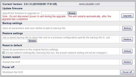
Information: Optional tips for your reference.
          Information

Safety Precautions

Before using this device, please read the following important information carefully to
eliminate or reduce any possibility of causing damage and personal injury.
1. Do use the AC adapter that comes with this device (if it is available). Use of other
   AC adapter may lead to malfunction, heat up, electrical shock, fire or injury.
2. Keep the space around the adapter clear in case you need to quickly unplug the
   adapter during emergencies.
3. Do not install near any heat sources such as radiators or other devices.
4. Use only attachments/accessories such as cover and plates specified by the
   manufacturer.
5. Do not touch the unit or the AC adapter when power on.
6. Unplug the device if you don’t need to use for a certain period of time to avoid
   any risks of causing fire.
7. Do not disassemble the NVR case.
8. Please contact your distributor to obtain compatible IP camera list.
9. Damaged wire could cause fire or electrical shock. Keep the power cord straight
   and without being twisted, bended, or scraped.
10. Moisture condensation may occur inside this device and cause malfunction at
    these conditions:
      •   When this device is moved directly from a cold to a warm location.
      •   After a cold room is heated.
      •   When this device is placed in a damp room.
   To avoid the moisture condensation, you are recommended to follow the
   procedure:
      •   Seal this device in a plastic bag for it to adapt to room conditions.
      •   Wait for 1 ~ 2 hours before removing this device from the bag.
11. Avoid excessive smoke, mechanical, dust, or direct sunlight.
12. Do not replace incorrect type of battery on the Server main board. There is risk of
    explosion if the battery is replaced by an incorrect type. Dispose of used batteries
    according to the instructions.

                                            2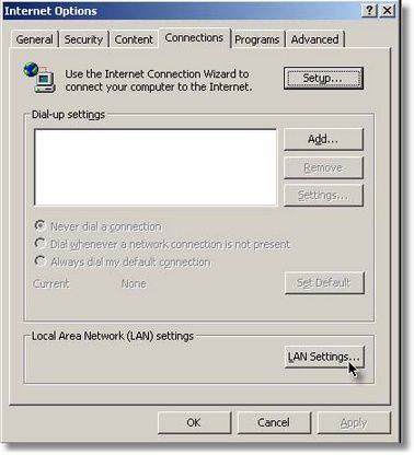
The mark shown to the left is in compliance with the Waste
                         Electrical and Electronic Equipment Directive 2002/96/EC
                         (WEEE). The mark indicates the requirement NOT to dispose
                         the equipment as unsorted municipal waste, but use the return
                         and collection systems according to local law. If the batteries,
          Information    accumulators and button cells included with this equipment,
                         display the chemical symbol Hg, Cd, or Pb, then it means that
                         the battery has a heavy metal content of more than 0.0005%
                         Mercury, or more than 0.002% Cadmium, or more than 0.004%
                         Lead.

Main NVR Features
      •     Real-time live view supervision
      •     Scheduled Recording, Manual Recording and Event Triggered Recording
      •     Record Playback
      •     Motion Detection
      •     TCP/IP / SMTP / DNS / DDNS / UPnP Support
      •     PTZ camera control

Minimum System Requirements1
The NVR is recommended to work with personal computer or network that meets the
following requirements:
                            Microsoft® Windows® 2000 Professional, XP Home Edition
    Operation System
                            or XP Professional, Vista, 7 compatible
    CPU                     Intel Pentium® 4 processor or above
                            TCP/IP Network protocol installed. (DHCP, Static IP, DDNS,
    Network Protocol
                            SMTP)
    Web Browser             Internet Explorer 6.0 or later 2
    RAM                     256 MB (512 MB or higher recommended)
                            10/100 Mbps Ethernet Card and Category 5 cables for
    Ethernet Interface
                            network connections 3
                            CD-ROM/DVD Drive, Video card that supports 16-bit color
    Others
                            or greater, 800 MB Free Hard Disk Space

Box Contents4
Before you start installing your NVR, check the box contents to make sure all parts
are included. If any items are damaged or missing, please contact the vendor where
you purchased your NVR or our customer service directly.
1
  The system requirements here are only a guideline, as in general the better the computer
(motherboard, processor, hard disk, RAM, video graphic card), the better the results.
2
   The program is available with Microsoft Windows and therefore is not included in the
Setup/Application CD-ROM of this product.
3
  These parts are not included in the package.
4
  Save the box and packing materials in case you need to transport this NVR in the future.
The product packaging can be recycled.

                                               3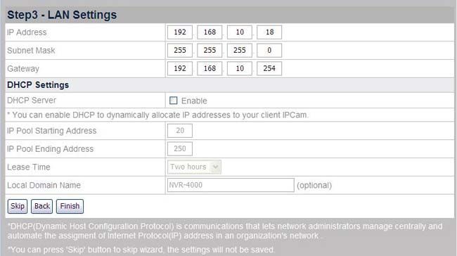
NVR 4000/4200/4300

1. NVR
2. Power Cable
3. AC Adapter
4. Reset Pin
5. User’s Guide
6. Installation CD

NVR Slim240

1. NVR
2. AC Adapter
3. User’s Guide
4. Installation CD

                     4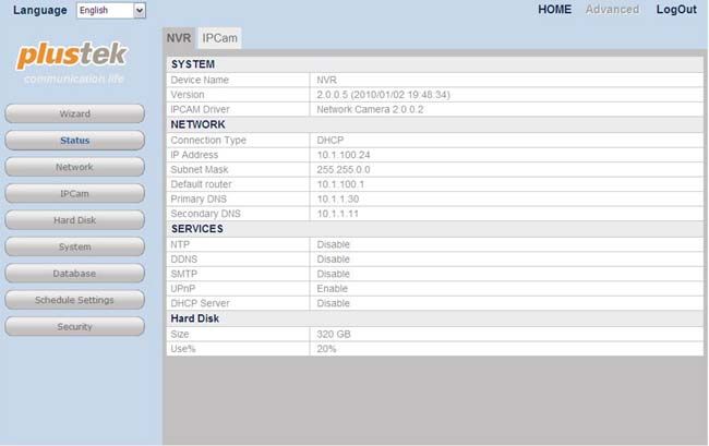
NVR 4200V

1. NVR
2. Reset Pin
3. User’s Guide
4. Installation CD
5. Cable Clasp
6. Cable Stabilizer Rack
7. Rack Screws
8. Power Cord Clasp
9. NVR Screws

                           5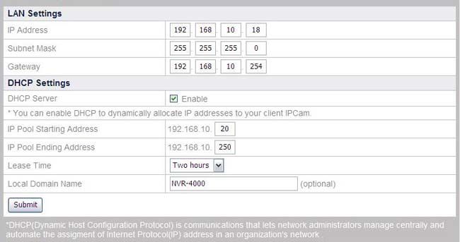
Overview

NVR 4000/4200

1. Power Indicator
2. HDD Indicator
3. WAN Indicator
4. LAN Indicators

5. 4 LAN Ports
6. WAN Port
7. COM Port
8. Power Hole
9. DC-Jack

10. RESET Hole

                     6
NVR 4300
1. Power Indicator
2. Status Indicator
3. HDD Indicator
4. WAN Indicator
5. LAN Indicators
6. 4 LAN Ports
7. WAN Port
8. COM Port
9. Power Hole
10. DC-Jack
11. I/O Interface 5
12. RESET Hole
5
Serious damage to the NVR may result if a device is connected to the I/O Interface that
exceeds its electrical capability.
The low voltage/current circuit and high voltage/current circuit are in the NVR circuit. Incorrect
wiring could damage the NVR.
7NVR Slim240
1. COM Port
2. 4 LAN Ports
3. WAN Port
4. DC-Jack
8NVR 4200V
1. Power Indicator
2. HDD Indicator
3. WAN Indicator
4. LAN Indicators
5. 4 LAN Ports
6. WAN Port
7. COM Port
8. Power Hole
9. DC-Jack
10. RESET Hole
9Chapter I. Setup the NVR
Before you setup the NVR (Network Video Recorder), please make sure all
components are available and ready. A list of the package contents is provided in the
Box Contents section of this guide. If any items are damaged or missing, please
contact the vendor where you purchased your NVR or our customer service directly.
Setup the NVR System
I. Connecting with IP Cameras
NVR 4000/4200/4300
To set up the NVR system in your LAN environment:
Please configure the IP address of the IP cameras before
connecting to the NVR.
Attention
1. Plug the RJ-45 connectors into LAN port of NVR and IP camera RJ-45 port.
2. Plug the RJ-45 connectors into WAN port and Router’s LAN port.
3. Turn on the Router (Router with UPnP on/off function is recommended).
4. Plug the AC adapter into the DC-Jack of the NVR. Attach the power cable to
the AC adapter. Plug the other end of the power cable into a standard AC
power outlet.
5. Connect PC or Laptop with Router LAN port.
6. Insert the Installation CD, included with your NVR, into your CD-ROM drive.
7. Double click the “vcredist_x86.exe” file in your language on the CD-ROM to
install the Microsoft Visual C++ 2005 SP1 Redistributable Package (x86).
8. Run the “Network Device Search Tool” application on the CD-ROM.
109. When the NVR lists in the Network Device Search Tool window, your NVR
works properly.
NVR Slim240
To set up the NVR system in your LAN environment:
Please configure the IP address of the IP cameras before
connecting to the NVR.
Attention
1. Plug the RJ-45 connectors into LAN port of NVR and IP camera RJ-45 port.
2. Plug the RJ-45 connectors into WAN port and Router’s LAN port.
3. Turn on the Router (Router with UPnP on/off function is recommended).
4. Plug the AC adapter into the DC-Jack of the NVR. Plug the other end of the
power cable into a standard AC power outlet.
5. Connect PC or Laptop with Router LAN port.
6. Insert the Installation CD, included with your NVR, into your CD-ROM drive.
7. Double click the “vcredist_x86.exe” file in your language on the CD-ROM to
install the Microsoft Visual C++ 2005 SP1 Redistributable Package (x86).
8. Run the “Network Device Search Tool” application on the CD-ROM.
9. When the NVR lists in the Network Device Search Tool window, your NVR
works properly.
11NVR 4200V
To set up the NVR system in your LAN environment:
Please configure the IP address of the IP cameras before
connecting to the NVR.
Attention
1. Put the cable clasp onto the RJ-45 cables. Put that end of the cable
connectors through the cable stabilizer rack. Clasp the cable clasp into the
cable stabilizer rack.
2. Plug the RJ-45 connectors into LAN port of NVR and IP camera RJ-45 port.
3. Plug the RJ-45 connectors into WAN port and Router’s LAN port.
4. Fasten the rack screws to fix the cable stabilizer rack on the rear panel of the
NVR.
125. Turn on the Router (Router with UPnP on/off function is recommended).
6. Plug the power cord clasp into the hole above the DC-JACK.
7. Plug your suitable power source cable into the DC-Jack of the NVR. Put the
power cord into the power cord clasp.
8. Fasten the NVR screws to fix the NVR at the desired position.
9. Connect PC or Laptop with Router LAN port.
10. Insert the Installation CD, included with your NVR, into your CD-ROM drive.
11. Double click the “vcredist_x86.exe” file in your language on the CD-ROM to
install the Microsoft Visual C++ 2005 SP1 Redistributable Package (x86).
12. Run the “Network Device Search Tool” application on the CD-ROM.
13. When the NVR lists in the Network Device Search Tool window, your NVR
works properly.
13II. Connecting with CCTV Cameras and Video Servers
NVR 4000/4200/4300
To set up the NVR system in your LAN environment:
Please configure the IP address of the Video Server before
connecting to the NVR.
Attention
1. Connect the AC adapter to the DC IN Jack of the video server.
2. Plug the AC adapter into a standard wall outlet.
3. Connect the coaxial cable to the video input port of the Video Server from the
CCTV camera.
4. Connect CCTV power cord to an outlet, if any.
5. Plug the RJ-45 connectors into LAN port of NVR and Ethernet Port of the
video server.
6. Plug the RJ-45 connectors into WAN port and Router’s LAN port.
7. Turn on the Router (Router with UPnP on/off function is recommended).
8. Plug the AC adapter into the DC-Jack of the NVR. Attach the power cable to
the AC adapter. Plug the other end of the power cable into a standard AC
power outlet.
9. Connect PC or Laptop with Router LAN port.
10. Insert the Installation CD, included with your NVR, into your CD-ROM drive.
11. Double click the “vcredist_x86.exe” file in your language on the CD-ROM to
install the Microsoft Visual C++ 2005 SP1 Redistributable Package (x86).
12. Run the “Network Device Search Tool” application on the CD-ROM.
1413. When the NVR lists in the Network Device Search Tool window, your NVR
works properly.
NVR Slim240
To set up the NVR system in your LAN environment:
Please configure the IP address of the Video Server before
connecting to the NVR.
Attention
1. Connect the AC adapter to the DC IN Jack of the video server.
2. Plug the AC adapter into a standard wall outlet.
3. Connect the coaxial cable to the video input port of the Video Server from the
CCTV camera.
4. Connect CCTV power cord to an outlet, if any.
5. Plug the RJ-45 connectors into LAN port of NVR and Ethernet Port of the
video server.
6. Plug the RJ-45 connectors into WAN port and Router’s LAN port.
7. Turn on the Router (Router with UPnP on/off function is recommended).
8. Plug the AC adapter into the DC-Jack of the NVR. Plug the other end of the
power cable into a standard AC power outlet.
9. Connect PC or Laptop with Router LAN port.
10. Insert the Installation CD, included with your NVR, into your CD-ROM drive.
11. Double click the “vcredist_x86.exe” file in your language on the CD-ROM to
install the Microsoft Visual C++ 2005 SP1 Redistributable Package (x86).
12. Run the “Network Device Search Tool” application on the CD-ROM.
1513. When the NVR lists in the Network Device Search Tool window, your NVR
works properly.
NVR 4200V
To set up the NVR system in your LAN environment:
Please configure the IP address of the Video Server before
connecting to the NVR.
Attention
1. Connect the AC adapter to the DC IN Jack of the video server.
2. Plug the AC adapter into a standard wall outlet.
3. Connect the coaxial cable to the video input port of the Video Server from the
CCTV camera.
4. Connect CCTV power cord to an outlet, if any.
5. Put the cable clasp onto the RJ-45 cables. Put that end of the cable
connectors through the cable stabilizer rack. Clasp the cable clasp into the
cable stabilizer rack.
166. Plug the RJ-45 connectors into LAN port of NVR and Ethernet Port of the
video server.
7. Plug the RJ-45 connectors into WAN port and Router’s LAN port.
8. Fasten the rack screws to fix the cable stabilizer rack on the rear panel of the
NVR.
9. Turn on the Router (Router with UPnP on/off function is recommended).
10. Plug the power cord clasp into the hole above the DC-JACK.
11. Plug your suitable power source cable into the DC-Jack of the NVR. Put the
power cord into the power cord clasp.
1712. Fasten the NVR screws to fix the NVR at the desired position.
13. Connect PC or Laptop with Router LAN port.
14. Insert the Installation CD, included with your NVR, into your CD-ROM drive.
15. Double click the “vcredist_x86.exe” file in your language on the CD-ROM to
install the Microsoft Visual C++ 2005 SP1 Redistributable Package (x86).
16. Run the “Network Device Search Tool” application on the CD-ROM.
17. When the NVR lists in the Network Device Search Tool window, your NVR
works properly.
18Chapter II. Working with the NVR
Log in the NVR
Method I. Network Device Search Tool Application
Network Device Search Tool is an application that can detect the network camera(s)
and NVR(s) that you connect to an organization’s network or your PC.
1. Insert the CD-ROM into the CD-ROM drive of your PC.
2. Double click on the “Plustek Network Device Search Tool” file.
3. The Network Device Search Tool window is displayed.
4. Select and double click on the desired NVR.
5. The System Login page appears on the screen.
When you use the Internet Explorer to browse the website,
ActiveX controls may assure the normal display of images.
Information
196. When you log in your NVR for the first time, enter “admin” as your user name and
“admin” as your password.
7. Click “OK” to send the identification information for recognition.
The “admin” and “admin” are the default user name and
password for your first login of the NVR as Administrator.
Please change the default password as soon as possible. To
Attention change the password, please refer to the section “Users”.
Method II. IE Address Bar
When you connect the NVR to the Internet with static IP address, you may log in the
NVR by directly entering the IP address in the IE Address Bar.
If you are provided with dynamic IP address in an organization’s
network, please refer to the “Use the NVR with Dynamic IP
Information Address” section for more instructions.
1. Start the Internet Explorer, enter the IP address of the NVR in the IE address bar,
and press “Enter“ on the keyboard to launch the System Login page.
2. The System Login page is displayed.
3. Enter “admin” as your user name, “admin” as your password and click “OK”.
The “admin” and “admin” are the default user name and
password for your first login of the NVR as Administrator.
Please change the default password as soon as possible. To
Attention change the password, please refer to the section “Users”.
Wizard
This Wizard will guide you through the basic settings to complete your initial setup
fast and easy. You may define the “Device Name” for the NVR you use.
20Step 1 – System Settings
To set NVR Date & Time:
1. Select Time Zone from the drop-down list.
2. You may set the NVR date and time by any of the following two ways:
a. Synchronize the NVR with the computer time.
b. Manually set the Date and Time by entering the Date and Time in the
blanks.
Click “Next” to continue the settings.
Step 2 – WAN Settings
To choose the IP allocation methods:
1. Select either DHCP or static IP:
21• If you want your NVR to use a dynamic IP, select the “Obtain IP via
DHCP” radio button and your NVR will be assigned with any idle IP
address in your organization’s network.
• If you want your NVR to use a static IP, select the “Use the following IP”
radio button and fill in the blanks for IP address, subnet mask and
Gateway.
2. Enter the HTTP port if needed. The default port is 80.
To enter the DNS address if needed:
You may check “Obtain a DNS address automatically” radio button to obtain the DNS
address automatically. If you want the NVR to use a host name, you’ll need to enter
at least one (Primary) DNS address.
1. Enter the IP address of the “Primary DNS Address” provided by your ISP.
2. Enter the IP address of the “Secondary DNS Address” provided by your ISP.
Click “Next” to continue the settings.
Step 3 – LAN Settings
To enable NVR as DHCP Server:
1. Check “Enable” if you want the NVR to serve as a DHCP Server and
dynamically allocate IP addresses to the IP Camera(s) connected.
2. Enter the Starting and Ending IP Pool Addresses to define the IP Address
range of the IP Camera(s).
3. Enter the “Lease Time”.
4. Enter the “Local Domain Name” for the NVR if you want to visit the NVR by its
Local Domain Name within the LAN.
Click “Finish” to complete the settings, it takes about 60 seconds to reboot the
system. Follow the on-screen instructions to install all software that your NVR
requires.
22To Add a New IP Camera
1. Go to the “Advanced” page and click the menu “IPCam” “Device
Management”.
2. Click the “New” button to enter the “Device Information” window, and the NVR
will automatically detect the IP Camera connected with its “Device Name”, “IP
Address” and “Port”. You may click “Refresh” button to update connected
device information.
3. To add IP cameras that were not detected, click the “Manual” button in the
“Device Information” window to enter the “Add Device” window.
There are two other ways to add IP Cameras:
You may click “UPnP” button to automatically detect the connected
Information IP Cameras, and select the IP Camera by clicking the radio button
then click “Next” button to continue the settings.
You may click “History” button to display the IP Cameras you had
added previously in the “Device Management” list, and select the
IP Camera by clicking the radio button then click “Next” button to
continue the settings.
4. Enter the “Name” for the device and the name will show at the screen banner
on “Live View”, “Record View”, “Motion Detection” page; enter the “Device
Name”, “IP Address” and “WEB Port” of the IP Camera you’ve seen on the
23“Device Information” page; enter the “User Name” and “Password” of the IP
Camera. Enter the password again in “Confirm Password”.
5. Click “Next” to add the IP Camera information, and the “Connection Status”
window will show the status of the IP Camera you just added.
NVR Viewer Windows
Language
After logging in, the “Live View” page will be displayed. You may choose the system
language from the drop-down list.
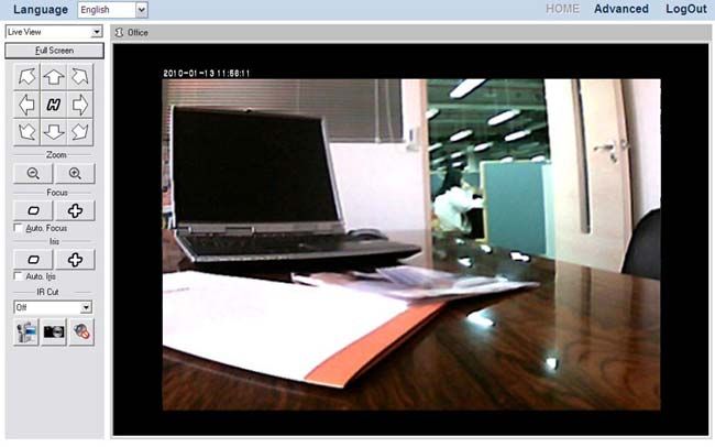
Live View
After logging in, the “Live View” page will show four camera screens, displaying the
live video stream captured by the cameras. Double-click the bar at the top of desired
camera window to display the desired channel.
There’re a few buttons for you to control the functions of the camera and NVR.
24To maximize the screen
Click on the “Full Screen” button to maximize the camera window.
Press the Alt + Esc buttons on the keyboard to exit the full screen.
6
To control the camera viewer
The buttons and their respective functions are shown in the following table:
Button Function
If you are using a PTZ network camera, the PTZ Setting button
will be activated. Click on the button to make PTZ adjustment
of the camera. By PTZ control, you may focus the network
camera to a desired position.
Click these arrow buttons to adjust the direction of the camera
lens. Click to reset the camera to its home position.
Click or to zoom in or zoom out.
Click or to adjust lens focus.
Tick this checkbox to enable auto lens focus.
Click or to adjust Iris levels.
Tick this checkbox to enable auto Iris.
If you set the “IR Cut” to “off”, the image is displayed in black &
white. If you set the “IR Cut” to “Auto”, the camera will turn the
filter off automatically when the surrounding light falls below
the specific requirement.
To manually record a video
1. Press down on the “Manual Record” button to start the recording process.
2. Press up on the “Manual Record” button again to stop the recording process.
3. The recorded video will be saved, and you may enter the “Record View” page by
selecting “Record View” from the drop-down list to play the recorded video.
6
The following functions are available only when the connected IP Camera is built with
related functions.
25To take a snapshot
1. Click the “Snapshot” button to capture the image shown in the current
viewer.
2. A note will pop out telling you the saving folder and filename of the snapshot. You
may go to the folder and find the snapshot picture. For Windows 7 users, you
may browse your disk drives to select a desired saving folder in the dialog that
opens.
To enable Audio function
The “Audio” button is available only when the connected IP Camera is built with
related functions. Go to the “Advanced” page and click the menu “IPCam” “Video
Settings”, if the “Enable Audio” option is checked, you may click on the “Audio” button
to enable or disable the audio function.
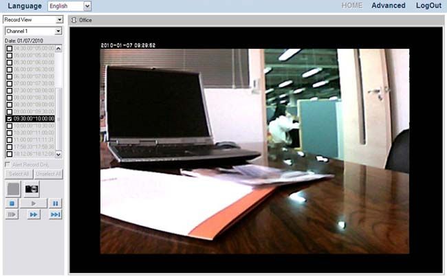
Record View
Select “Record View” from the drop-down list to display the page of Record View.
To select a normal record to play:
1. Select a desired Channel to configure settings. Click the button to select
a date from the popup window.
2. Click on the date you want to review in the calendar. The dates with video
records are displayed in bold fonts. Click “OK” to confirm the selection.
3. Tick the checkbox to select the time period from the list on the left.
4. Click “Select All” to select all records, and click “Unselect All” to unselect all
records. Click “PLAY” and the window will play the recorded video one by one.
265. Click the “Snapshot” button and you may take a snapshot for the image
displayed.
6. Click the buttons at the bottom of the Record View dialog to control the play of
the videos. The buttons and their respective functions are shown in the
following table:
Play
Stop
Pause
Fast Forward
Jump to the next section of the
recordings selected
Move forward one image at a time
To select an alarm record to play:
1. Select the “Alert Record Only” option.
2. Select a desired Channel to configure settings. Click the button to select
a date from the popup window.
273. Click on the date you want to review in the calendar. The dates with video
records are displayed in bold fonts. Click “OK” to confirm the selection.
4. Tick the checkbox to select the time period from the list on the left.
5. Click “Select All” to select all records, and click “Unselect All” to unselect all
records. Click “PLAY” and the window will play the recorded video one by one.
6. Click the “Snapshot” button and you may take a snapshot for the image
displayed.
7. Click the buttons at the bottom of the Record View dialog to control the play of
the videos. The buttons and their respective functions are shown in the
following table:
Play
Stop
Pause
Fast Forward
Jump to the next section of the
recordings selected
Move forward one image at a time
28Motion Detection
To set motion detection conditions for each camera:
1. Select “Motion Detection” from the drop-down list to enter the Motion
Detection page.
2. ”Motion Detection” dialog will display on the left side. Select a desired
Channel to configure settings.
3. From the ”Motion Detection” dialog, select a desired Motion Window to
configure settings.
If you don’t see any motion detection frame in the camera window, click
the “New” button in the “Motion Detection” dialog, and a red motion
detection frame will be created with the name “Untitled #0” and you may
configure settings for it.
If you see motion detection frames in the camera window, select a
“Motion Windows” from the drop-down list in the “Motion Detection”
dialog, and the motion window will be activated with red borders and you
may configure settings for it.
4. Drag the red borders of the active Motion Window to define the window shape,
size and position.
5. Enter the “Name” in the dialog.
6. In the “Detection” drop-down list, select “Included” if you want to detect the
motion of the area within the frame, or “Excluded” if you want to detect the
motion of the area outside the frame.
7. Adjust the sliders to define:
The color and luminance difference “Sensitivity” that will trigger the
motion detection.
29The “Object Size” that will trigger the motion detection.
The “History” – the duration an object appears within the motion
detection frame to trigger the motion detection.
8. Check “Display All Windows” to display all the motion windows in the camera
view. Uncheck the option if you only want to see the active motion window.
9. Click the “Delete” button to delete the active motion window.
10. Please make sure to click the “Apply” button in order to save the changes
you’ve made.
The Motion Detection settings for a camera won’t take effect until you
configure Motion Detection as an Event Trigger for the camera. Please
refer to the Event Settings section for more information.
Information
Log out the NVR
To exit the NVR page, click the “LogOut” button at the top right corner of the NVR’s
main page.
Please do NOT click on the button on the Internet Explorer
window to exit the NVR. Clicking on the button will not change
Attention the logged-in status of the user.
30Chapter III. Advanced NVR Configuration
The administrator has the right to access all the NVR functions, and can make
advanced configurations for the NVR according to the special needs.
To enter the Advanced settings page:
1. Click the “Advanced” button on the main page banner to enter the advanced
configuration page. On the left of the page shows the configuration menu.
There are 9 menus available: “Wizard”, “Status”, “Network”, “IPCam”, “Hard
Disk”, “System”, “Database”, “Scheduled Settings” and “Security”.
2. Click on each menu item to enter the submenus. You may configure settings
according to your special need.
The following describes the menus individually and the related settings.
Wizard
This Wizard will guide you through the basic settings to complete your initial setup
fast and easy. Go to the “Advanced” page and click the menu “Wizard” to display the
page of System Settings. You may define the “Device Name” for the NVR you use.
31Step 1 – System Settings
To set NVR Date & Time:
1. Select Time Zone from the drop-down list.
2. You may set the NVR date and time by any of the following two ways:
a. Synchronize the NVR with the computer time.
b. Manually set the Date and Time by entering the Date and Time in the
blanks.
Click “Next” to continue the settings.
Step 2 – WAN Settings
To choose the IP allocation methods:
1. Select either DHCP or static IP:
32• If you want your NVR to use a dynamic IP, select the “Obtain IP via
DHCP” radio button and your NVR will be assigned with any idle IP
address in your organization’s network.
• If you want your NVR to use a static IP, select the “Use the following IP”
radio button and fill in the blanks for IP address, subnet mask and
Gateway.
2. Enter the HTTP port if needed. The default port is 80.
To enter the DNS address if needed:
You may check “Obtain a DNS address automatically” radio button to obtain the DNS
address automatically. If you want the NVR to use a host name, you’ll need to enter
at least one (Primary) DNS address.
1. Enter the IP address of the “Primary DNS Address” provided by your ISP.
2. Enter the IP address of the “Secondary DNS Address” provided by your ISP.
Click “Next” to continue the settings.
Step 3 – LAN Settings
To enable NVR as DHCP Server:
1. Check “Enable” if you want the NVR to serve as a DHCP Server and
dynamically allocate IP addresses to the IP Camera(s) connected.
2. Enter the Starting and Ending IP Pool Addresses to define the IP Address
range of the IP Camera(s).
3. Enter the “Lease Time”.
4. Enter the “Local Domain Name” for the NVR if you want to visit the NVR by its
Local Domain Name within the LAN.
Click “Finish” to complete the settings, it takes about 60 seconds to reboot the
system. Follow the on-screen instructions to install all software that your NVR
requires.
33Status
NVR Status
To view the current NVR status
Go to the “Advanced” page and click the menu “Status” “NVR”, and the current
status of the NVR will display on the right.
You can alter some of the settings shown in this sector from other menu items.
34IPCam Status
To view the current IPCam status
Go to the “Advanced” page and click the menu “Status” “IPCam”, and you’ll see
the current status of the IP Camera(s) connected to your NVR. The NVR provides up
to four channels to connect up to four IP Cameras. The list shows the information of
the IP Cameras connected to respective channels.
Network
WAN
Go to the “Advanced” page and click the menu “Network” “WAN”. In the WAN
menu, you may configure the NVR’s WAN settings according to the network
connection conditions and your special needs. You may select desired options from
the drop-down list.
35TCP/IP
To choose the IP allocation methods:
1. Go to the “Advanced” page and click the menu “Network” “WAN”
”TCP/IP”.
2. Select either DHCP or static IP:
If the NVR adopts dynamic IP, check “Obtain IP via DHCP” radio button,
and your NVR will be assigned with any idle IP address in your
organization’s network.
If the NVR uses static IP, check “Use the following IP” radio button, and fill
in the blanks of IP address, subnet mask and Gateway.
3. Enter the HTTP port if needed. The default port is 80.
To enter the DNS address if needed:
You may check “Obtain a DNS address automatically” radio button to obtain the DNS
address automatically. If you want the NVR to use a host name, you’ll need to enter
at least one (Primary) DNS address.
1. Enter the IP address of the “Primary DNS Address” provided by your ISP.
2. Enter the IP address of the “Secondary DNS Address” provided by your ISP.
36DDNS
To configure DDNS settings:
1. Go to the “Advanced” page and click the menu “Network” “WAN”
”DDNS”.
2. If you want the NVR to act as DDNS Service, click “Enable”.
3. Enter the address of “DDNS Server”, “User Name”, “Password”, and “Host
Name”.
4. Click “Submit” to save the setting.
SMTP
Go to the “Advanced” page and click the menu “Network” “WAN” ”SMTP”. In
this menu you can configure several email addresses. The NVR can automatically
send alarm messages from the configured email addresses when an event is
triggered. (See Event Settings for more information about automated email alert.)
To add email addresses:
1. Go to the “Advanced” page and click the menu “Network” “WAN”
”SMTP”.
2. Click the “Add” button and enter the SMTP information in this page.
373. Enter the “Name”, “Sender Address”, “Mail Server”, “User Name” and
“Password” of the email account. Enter the password again in “Confirm
Password”.
4. Click “Submit” to save the setting.
To set the priority for the email addresses:
1. Go to the “Advanced” page and click the menu “Network” “WAN”
”SMTP”.
2. When more than one email address has been added, you may click on the
radio button in front of a sender address and click “UP” or “DOWN” button to
move the email address’s priority in the list.
FTP
In this page you can configure several FTP servers. The NVR can automatically send
recorded images to the configured FTP server when an event is triggered. (See
Event Settings for more information about automated uploading images to the FTP
server.)
To add an FTP Server:
1. Go to the “Advanced” page and click the menu “Network” “WAN” ”FTP”.
2. Click “Add” button and enter the FTP server information in this page.
383. Enter the following information:
Connection Name: Enter the name for this FTP Server, e.g. FTP.
Server: Enter the address of this FTP Server, e.g. ftp.xyz.org or
10.1.100.62.
User Name: Enter your user name to log in with, e.g. Mary Lo.
Password: Enter the password to log in with, e.g. 157639.
Confirm Password: Enter the password again.
Server Directory: Enter the directory path on the FTP server to save the
files in, e.g. NVR.
4. Click “Submit” to save the settings.
To set the priority for the FTP Servers:
1. Go to the “Advanced” page and click the menu “Network” “WAN” ”FTP”.
2. When more than one FTP Server has been added, you may click on the
radio button in front of a FTP Server Name and use “UP” “DOWN” button to
change the FTP Server’s priority in the list.
LAN
39To enable NVR as DHCP Server:
1. Go to the “Advanced” page and click the menu “Network” “LAN”.
2. Check “Enable” if you want the NVR to serve as a DHCP Server and
dynamically allocate IP addresses to the IP Camera(s) connected.
3. Enter the Starting and Ending IP Pool Addresses to define the IP Address
range of the IP Camera(s).
4. Enter the “Lease Time”.
5. Enter the “Local Domain Name” for the NVR if you want to visit the NVR by its
Local Domain Name within the LAN.
Client List
To view the current DHCP Client List
Go to the “Advanced” page and click the menu “Network” “Client List”, and you’ll
see the current list of the IP Camera(s) connected to your NVR via DHCP (dynamic
IP). Note that the IP Camera(s) connected to your NVR via fixed IP address will not
be listed on this page. The DHCP Client List menu displays the IP addresses, MAC
addresses and the names of the IP cameras via the DHCP connection. In addition,
after you connect a new IP camera to the NVR via DHCP, you may click “Refresh” in
this page to renew the DHCP Client List.
IPCam
In this menu, you can configure the setting for the IP Cameras connected to your
NVR.
40Device Management
To add a new IP Camera
1. Go to the “Advanced” page and click the menu “IPCam” “Device
Management”.
2. Click the “New” button to enter the “Device Information” window, and the NVR
will automatically detect the IP Camera connected with its “Device Name”, “IP
Address” and “Port”. You may click “Refresh” button to update connected
device information.
3. To add IP cameras that were not detected, click the “Manual” button in the
“Device Information” window to enter the “Add Device” window.
There are two other ways to add IP Cameras:
• You may click “UPnP” button to automatically detect the connected
Information IP Cameras, and select the IP Camera by clicking the radio button
then click “Next” button to continue the settings.
• You may click “History” button to display the IP Cameras you had
added previously in the “Device Management” list, and select the
IP Camera by clicking the radio button then click “Next” button to
continue the settings.
414. Enter the “Name” for the device and the name will show at the screen banner
on “Live View”, “Record View”, “Motion Detection” page; enter the “Device
Name”, “IP Address” and “WEB Port” of the IP Camera you’ve seen on the
“Device Information” page; enter the “User Name” and “Password” of the IP
Camera. Enter the password again in “Confirm Password”.
5. Click “Next” to add the IP Camera information, and the “Connection Status”
window will show the status of the IP Camera you just added.
To change the IP Camera information
1. In the Device Management window, you may select the IP Camera by clicking
the radio button before its name.
2. You may click the “Edit” button to edit the Name of the IP Camera.
3. You may click the “Delete” button to delete the IP Camera.
4. You may click the “Restore” button to restore the IP Camera to its factory
default values.
5. You may click the “Restart” button to restart the IP Camera.
42Video Settings
To set video display:
1. Go to the “Advanced” page and click the menu “IPCam” “Video Settings”.
2. Select the camera you want to adjust the video settings for from the drop-
down list.
3. In “Image Appearance” section, you may adjust the Video format, Resolution,
Quality, Rotation angle, Color saturation, Brightness, and Sharpness for the
video image displayed by the camera.
4. In the “Display Setting” section, you can configure the lens operation modes
of the connected IP Camera.
The “Display Setting” function is available only when the
connected IP Camera is built with related lens functions.
Attention
If you select “Right” from the drop-down list, it displays the image
recorded by the right-side lens of the connected IP Camera.
If you select “Left”, it displays the video recorded by the left-side lens of
the connected IP Camera.
If you select “Both”, it horizontally displays the videos recorded by both
lenses of the connected IP Camera.
43If you select “RiL”, the video recorded by the right-side lens of the
connected IP Camera is displayed on the full monitor screen while a small
video recorded by the left-side lens is displayed in an inset window.
If you select “LiR”, the video recorded by the left-side lens of the
connected IP Camera is displayed on the full monitor screen while a small
video recorded by the right-side lens is displayed in an inset window.
If you select “Auto”, the connected IP Camera will be activated to detect
the lighting in the environment and determine the “lux” level of the
detected light. You can select a desired “lux” level from the “lux” drop-
down list.
5. In the “Audio Settings” section, you may adjust the audio settings.
The “Audio Settings” function is available only when the
connected IP Camera is built with related functions.
Attention
6. In the “Overlay Settings” section, you can add some text information to the
video image, such as Date/time and a text title. You may choose Top or
Bottom from the drop-down list to display the information at the top or bottom
of the image. The text information will be shown in live view, snapshot and
recorded video.
7. Enter the camera frame rates. The frame rates may range from 1 to 30 fps.
8. Click “Submit” to save the settings.
9. Click “Preview” to preview the video settings you have made.
To estimate recording capacity:
Actual recording capacity may differ depending on the hard disk size, the image
quality and the record Frame rate. For example, NVR hard disk is 320GB and you
want to record one channel 24 hours a day. If you set the image quality at Normal
quality (the image size is about 48 KB) and the record Frame rate at 10 fps, you may
approximately record about 7.72 days.
Disk data recording chart (approximately)
Frame Quality Hard disk capacity (days)
rate (Image 250GB 320GB 500GB 750GB 1000GB 1250GB 1500GB
quality)
10 fps High 3.02 3.86 6.03 9.04 12.06 15.07 18.08
(frames (96KB)
per Normal 6.03 7.72 12.06 18.08 24.11 30.14 36.17
second) (48KB)
Low 12.06 15.44 24.12 36.16 48.22 60.28 72.34
(24KB)
Notes:
Recording conditions: 1 channel, recording time: 24 hours/day.
All above figures are estimates, actual figures may differ depending on the
complexity of the real situation.
44Hard Disk
Go to the “Advanced” page and click the menu “Hard Disk” to check the size and
status of the hard disk.
If you want to format the hard disk, you can click on the “Format” button, but please
note that all the data in the hard disk will be formatted.
System
Users
Go to the “Advanced” page and click the menu “System” “Users” to display the
Users page. We offer an Administrator account with the User Name “admin” and
default Password “admin”. Please change the administrator’s password to avoid
unauthorized usage.
The “administrator” can add several “General Users”, “Operators” or “Top Users”. A
“General User” is only authorized to view the live video of the cameras in the “Live
View” page. An “Operator” and a “Top User” are authorized to view the video of the
cameras in the “Live View”, “Record View”, “Motion Detection” page and is also
allowed to view the settings in “Advanced” pages, but is not allowed to change
settings. A “Top User” is allowed to control the camera viewer. The “Administrator”
has access right to all the functions of the NVR in the “Live View”, “Record View”,
“Motion Detection” and “Advanced” pages.
45You can also read