Closed Circuit Television Specification Guidelines - February 2018 - University of Tasmania
←
→
Page content transcription
If your browser does not render page correctly, please read the page content below

Closed Circuit Television

Specification Guidelines

        February 2018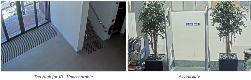
CCTV Specification Guidelines,
for the University of Tasmania

         CONTENTS

         1.0    INTRODUCTION ............................................................................................................. 1
         2.0    BACKGROUND............................................................................................................... 1
         3.0    SPECIFICATION REQUIREMENTS............................................................................... 1
         4.0    CAMERA SELECTION ................................................................................................... 2
         5.0    CAMERA PERFORMANCE AND MOUNTING .............................................................. 6
         6.0    STORAGE ..................................................................................................................... 14
         7.0    VIDEO MANAGEMENT SYSTEM ................................................................................ 14
         8.0    CONFIGURATION ........................................................................................................ 14
         9.0    WORKS EXECUTION ................................................................................................... 18
         10.0   TESTING AND COMMISSIONING ............................................................................... 19
         11.0   PRACTICAL COMPLETION (HANDOVER) ................................................................. 23
         12.0   RECORD OF WORK (AS INSTALLED/BUILT) ............................................................ 23
         13.0   WARRANTIES .............................................................................................................. 23
         14.0   CAMERA SCHEDULE EXAMPLE ................................................................................ 25
         15.0   ANALYTICS SCHEDULE .............................................................................................. 25

FEB-18                                                                                                                                        ii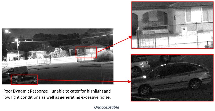
CCTV Specification Guidelines,
for the University of Tasmania
1.0 INTRODUCTION
This guideline is intended to inform a performance based specification of CCTV cameras and
systems for the University of Tasmania. Each project’s CCTV requirements are unique and
will require input from the University to ensure its requirements are firstly determined and then
met. The text and images within this guideline may be used explicitly for this purpose.
2.0 BACKGROUND
The University is increasing its use of security technology, in particular CCTV to provide more
automated security intelligence.
For this, high quality video and surveillance is required as an essential foundation.
The degree of variability for each project or works can be reasonable, primarily due to the
wide and evolving range of CCTV cameras and their ability meet the surveillance
requirement.
The current Video Management System (VMS) used by the University is Geutebruck. All
systems installed will extend, or be part of, this enterprise wide system. As such all hardware
must be compatible or agreement obtained from Geutebruck to create compatibility prior to
installation.
As a simplified means of explaining the system, refer to the below diagram.
IP Camera IP Camera
University Data Network,
Security VLAN
Geutebruck Geutebruck
Recorder Management Server
(Local) (Centrally hosted)
2.1 EXISTING SYSTEMS
A reasonable degree of existing cameras are analogue and have been IP enabled through
the use of IP encoders. If you are unable to determine if an existing camera is analogue or
digital, specify for a new digital camera.
3.0 SPECIFICATION REQUIREMENTS
CCTV works specifications must cover at minimum:
Camera performance & functionality;
Storage performance & functionality;
VMS works;
Software configuration;
Works execution; and
Commissioning / testing.
FEB-18 1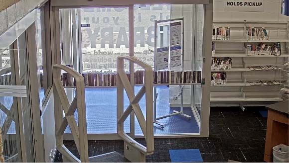
CCTV Specification Guidelines,
for the University of Tasmania
A camera schedule must also be developed and provided with the specification.
It is recommended to number all scheduled cameras and incorporate reference on
co-ordinated reflected ceiling plans.
CCTV design software packages can greatly assist the process of design, and selection of
cameras. Such packages are available from JVSG.
http://www.jvsg.com/software/ip-video-system-design-tool/
Alternatively, 3D modelling software with appropriate camera models, plugins or extensions
can be used such as Trimble Sketchup with an Axis camera extension.
http://www.sketchup.com/ and https://www.axis.com/au/en/tools/axis-camera-extension
Proposed CCTV systems should be modelled in a 3D design program and presented to the
University to demonstrate the outcomes for each device at its intended location. The
modelling should be based on the selected camera model, lens, mounting height and
horizontal field of view (HFOV) that will be delivered.
4.0 CAMERA SELECTION
The contractor shall select and use only cameras, including accessories and lensing that fulfil
the requirements specified within this section.
Compliance with performance aspects of the requirements will be based on the replay of
recorded images through various times of the day and night as further specified.
The contractor is to obtain samples of all their selected or proposed camera types and
undertake testing prior to final selection and installation.
If the requirements / outcomes are failed to be met, as determined by the University within the
defects liability period, the contractor must replace, free of charge, any systems or equipment
under their scope including but not limited to cameras, lensing or accessories required to
ensure the system complies with the required outcomes.
All cameras selected must be compatible with the University’s Geutebruck VMS unless
guarantee is obtained from Geutebruck to incorporate compatibility prior to works being
undertaken.
Cameras shall only be of the following manufacture unless otherwise authorised by the
University’s Security Technical Officer:
Axis
Panasonic
Pelco
Sony
All cameras used shall provide as a minimum:
Imaging of target areas without automatic gain control increasing graininess or noise
within the viewed image;
Images of moving targets free of motion blur, smear or ghosting;
1080 horizontal lines of resolution at 12.5 frames per second during motion periods;
Use a fully conformant Onvif Profile S specification;
Motion detection recording on Geutebruck recording appliances;
True wide or high dynamic response suitable for the application;
Progressive scanning;
FEB-18 2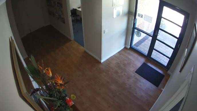
CCTV Specification Guidelines,
for the University of Tasmania
Automatic black level to enhance the contrast by removing veiling glare from the
picture;
A “lens wizard” during lens back focus setup to allow focusing at maximum iris
opening to ensure the object of interest within the field of view always remains in
focus.
Through-the-lens automatic tracking white balance.
4.1 Internal Cameras
Cameras used internally for the surveillance of the internal building must have some
resistance against tampering.
Cameras located nearby or providing surveillance of areas with glazing or daylight shall have
high dynamic range. Other cameras located in areas with only artificial lighting that is not
subject to rapid significant changes in illumination may have standard dynamic range.
Cameras providing surveillance of corridors, hall ways or the like, if greater than 4:3 (1.33:1)
aspect ratio image shall utilise a 90 degree mode to increase coverage.
If cameras are covering entry / exit points or areas that provide access between levels,
resolution outcomes (Detail Resolution) of either Identification or Recognition shall apply.
4.2 External Cameras
Cameras used externally for the surveillance of the external building or site must be vandal
and weather resistant. External cameras are to provide minimum performance levels where
there is no appreciable light source. Graininess in picture is deemed not acceptable.
External cameras must have low light capability for night-time operation and exceptional
backlight compensation for daytime operation. Low light cameras utilising technologies which
compromise quality or resolution outcomes for scenes containing motion shall not be
accepted. SensUP or similar technologies affecting these outcomes will not be accepted.
Cameras shall provide selectable on/off backlight compensation with back light compensation
and wide/high dynamic range operating at the same time.
4.3 Dynamic Range and Response, Low Lighting Examples
The following are example images to demonstrate the unacceptable and acceptable outcome
of a cameras dynamic range and response, and low lighting conditions.
Acceptable Not Acceptable
FEB-18 3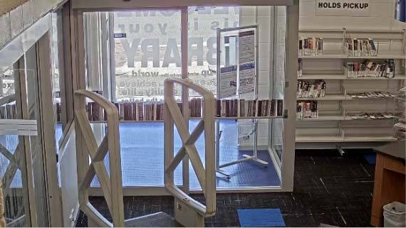
CCTV Specification Guidelines,
for the University of Tasmania

                 Acceptable at 0.1 Lux illumination                          Not Acceptable

            Acceptable at 0.1 Lux illumination                           Not Acceptable

                           Acceptable                                       Not Acceptable

4.4      Detail Resolution
         The following Detail Resolutions in Pixels per Meter (PPM) must be achieved when scheduled
         at all hours. In the event there is insufficient lighting available to provide these outcomes,
         supplementary lighting, including infrared shall be fitted to maintain compliance.

FEB-18                                                                                               4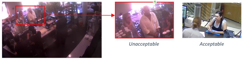
CCTV Specification Guidelines,
for the University of Tasmania

4.4.1    Identification
         Cameras scheduled as being required to provide identification use imaging are required to
         deliver 303 PPM imaging of the target area (entry / exit door, counter, chokepoint or other
         identified).

4.4.2    Recognition
         Cameras scheduled as being required to provide recognition use imaging are required to
         deliver 160 PPM imaging of the target area (waiting room, reception area, general circulation).

4.4.3    Observation
         Cameras scheduled as being required to provide observation use imaging are required to
         deliver 100 PPM imaging of the target area (vehicular / personnel traffic flows).

4.4.4    Detection
         Cameras scheduled as being required to provide detection use imaging are required to deliver
         62 PPM imaging of the target area (general internal / external).

FEB-18                                                                                                 5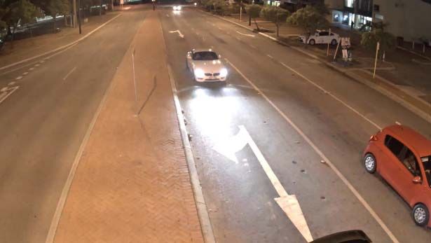
CCTV Specification Guidelines,
for the University of Tasmania

4.5      Integral Infrared Illumination and IR Cameras
         Cameras incorporating inbuilt infrared illumination shall not demonstrate any reflection from
         the IR light blocks within the lens or picture. The cameras IR shall provide images free of
         graininess or artefacts within the target area through times of low or no light.
         IR cameras shall also utilise adaptive power technologies that removes blooming / hotspots
         within the images.

4.6      Full Body Cameras
         Full body cameras shall allow the use of C or CS Mount type lenses and shall accept fixed iris
         lenses, manual iris lenses, DC auto-iris lenses, and video-iris lenses. For ease of installation,
         the camera shall auto detect the type of lens used and optimize performance accordingly.

         Fully body cameras fitted externally onto buildings where mounted below 3.5M AFFL shall be
         enclosed in a protective housing.

5.0      CAMERA PERFORMANCE AND MOUNTING
         Cameras are to be mounted in locations that provide access for maintenance and servicing,
         and shall be mounted at a height to provide clear images of the target area.

         Cameras shall be mounted and adjusted so they have no direct view of any light source, nor
         have any ceiling or luminaires in the cameras view wherever practical. Placement shall take
         into account the arc of the sun throughout summer, autumn, winter and spring as well as
         reflectivity changes off surfaces during the seasons.

5.1      External Cameras
         Cameras fitted externally on structures and freestanding poles shall not be mounted at such a
         level that allows ease of access from persons standing on the ground or on nearby fixed /
         movable objects.

         External Cameras shall be rated at (Ingress Protection) IP 66 minimum unless they may be
         subject to pressure cleaning whereby they are required to be rated at IP 68.

         External cameras shall be rated to meet or exceed the IK10 impact protection standard.

         All cabling entering camera housings shall be enclosed in PVC clad flexible steel conduit with
         suitable terminations.

         The camera mounting bracket or pole shall safely support the weight of the camera and any
         other attached devices. It shall also be designed to take into account the windage (drag) of the
         camera and other attached devices at the locations rated maximum wind loading and be
         designed to minimise any pole deflection affecting camera and imaging performance outcomes.

FEB-18                                                                                                   6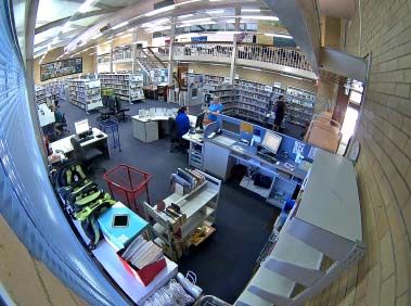
CCTV Specification Guidelines,
for the University of Tasmania

5.2      Camera Performance
Camera suitability and performance shall be tested against the reproduced image which has been
recorded.

These reviews shall be completed at various hours throughout the day including dusk, dawn, harsh
light times (midday, in the case of traffic cams headlights and spotlights) and low light hours. The
assessment of images suitable for identification where required will be based on low light
performance outcomes. Shown below are issues associated with performance outcomes, including
examples of unacceptable and acceptable results.

5.2.1    Dynamic Range
         Dynamic range refers to the CCTV cameras ability to interpret and display images in varying
         light conditions.

         The higher the dynamic range, the better the cameras ability to cater for variances within
         lighting conditions including highlight and low light aspects.

                                                                                          Unacceptable

         Note:
         It is important to understand that manufacturer data
         sheets and supporting documentation only relate to
         the capability of the camera and not to the functional
         outcomes that is achieved by the device once
         installed. This is due to the varying environmental
         and site conditions in which the cameras are
         installed and subsequently required to operate. As
         such a proper testing regime is essential prior to the
         purchase and installation of any equipment.
                                                                                   Acceptable

5.2.2    Focus
         Camera Lenses have not been focused correctly to
         produce a crisp image. Cameras may also be in-
         focus throughout the day but go out of focus at
         night.
         This is a result of poor installation practices whereby
         the cameras have not been configured for the (1)
         available scene lighting, (2) back-focused correctly,
         or (3) configured to operate with the optics
         associated with a dome camera’s bubble.
                                                                                 Unacceptable

                         Unacceptable                               Acceptable

FEB-18                                                                                                   7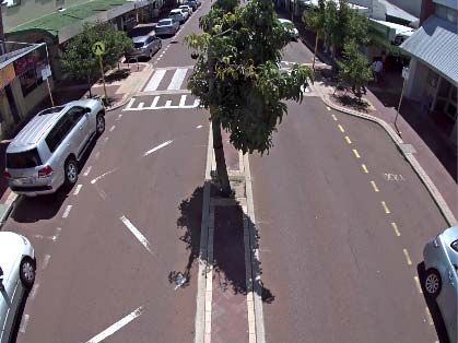
CCTV Specification Guidelines,
for the University of Tasmania

5.2.3 Exposure
5.2.3.1 Overexposed or Flaring

         Images can be described as overexposed when the amount of light allowed entering through
         the lens is greater than intended, which results in a brighter photo image.

         The correct selection, installation and commissioning processes associated with close circuit
         television infrastructure will correct this issue.

                       Unacceptable                                    Acceptable

5.2.3.2 Underexposed
        Underexposed refers to the amount of allowed light through the cameras lens is not sufficient
        to produce acceptable images and will be darker than the overexposed or correctly exposed
        picture.

         The correct selection, installation and commissioning processes associated with close circuit
         television infrastructure will correct this issue.

                          Unacceptable                                    Acceptable

FEB-18                                                                                                   8
CCTV Specification Guidelines,
for the University of Tasmania
5.2.4 Graininess and Noise
The Graininess is caused by the automatic gain control within the camera trying to compensate
for low light conditions it cannot handle. As the camera amplifies the picture to try and get a
good image it also amplifies the noise (graininess).
Owing to the way images are compressed within modern CCTV systems, in systems containing
Hi-Definition cameras, this noise can result in the storage required increasing by up to 900%
(above daytime storage levels) in low light conditions (when nothing is happening).
5.2.5 Smear
Incorrect camera selection or configuration combined with motion
and lighting may cause loss of resolution in moving targets.
Known as motion smearing
and occurs when the
camera amplifies noise
which degrades the image.
Unacceptable
5.2.6 License Number Plate Capture
Cameras designated to capture number plates shall complete this function regardless of the
speed of the vehicle and lighting condition of the scene
Acceptable Unacceptable
FEB-18 9CCTV Specification Guidelines,
for the University of Tasmania
5.2.7 Slow Shutter Speed & the Inability to Capture Moving Targets at Night Time
Whilst most camera images look good through the day (insert), it is during lowlight or harsh light
conditions when the failings of the camera and its ability to produce acceptable imaging is
demonstrated.
Camera manufacturers frequently used techniques which involve extending the time that the
shutter remains open to enable the camera to produce images in low light conditions. The
resultant effect is that background remains crisp and in focus, whilst moving targets become
nothing more than a blur. This renders the camera unsuitable for producing night-time images
where any detail is required on a moving target to provide identification or trying to resolve what
has happened.
Unacceptable
5.2.8 Lack of Resolution
Simply put, resolution refers to the number of pixels on the target. The greater the amount of
pixels on a subject, the greater the ability to define detail (in a perfect world).
The problem is that the clarity of the image may be affected by other conditions as such
resolution or detail on target may be caused by (main ones):
1. Poor dynamic range (1) – Edge Detail being compromised due to light,
2. Lens Selection (2) – trying to cover too much in one picture.
1. Poor Dynamic Range
2. Lens Selection - Same Camera/ Different Lens Adjustment
Resolution Required for
ID by ANZPAA
Guidelines
The wider the cameras Note: Cameras and imaging devices produce
view, the less detail is differing results depending on the amount of
captured light available.
When installing CCTV systems, the outcomes
related for the imaging device should be based
on night-time or harsh light reproduction and
not solely on daytime imaging.
FEB-18 10CCTV Specification Guidelines,
for the University of Tasmania
5.2.9 Incorrect Positioning and Adjustment
5.2.9.1 Entries
The position of scheduled identification cameras shall be such that the camera is no more than 15°
above the horizontal plane of 1.8 m target height. When entry cameras are too high all you will see is
heads or hats.
Unacceptable - Too High Unacceptable
FEB-18 11CCTV Specification Guidelines,
for the University of Tasmania
5.2.9.2 Mounting Height
Mounting heights of CCTV infrastructure should be low enough as to provide recognition or
Identification of an event.
Views looking at Walls or Lights provide no benefit except to
reduce resolution on the target and in the case of lighting, may
affect the cameras ability to produce acceptable pictures.
Field of view too wide, looking at walls and lights Unacceptable - Too High
5.2.9.3 Looking at Sky or Lights
Looking at Lights or the sky is unproductive. Apart from wasting the possible additional
surveillance of a target or area, the cameras also have to cater for the flair and dynamic range
of lighting as well as darker scenes away from the lights.
Unless there is a special requirement, it is bad practice to set cameras up in this way. These
cameras will be rejected.
Looking at sky and street lights Unacceptable - Sky filling 50% of the image
FEB-18 12CCTV Specification Guidelines,
for the University of Tasmania
5.2.10 Alignment
Although not technically incorrect, straightening of images wherever possible ensures a better
viewing experience. Cameras will be aligned to produce straight images.
Image not straight
Image not straight
5.2.11 Environmental Conditions
5.2.11.1 Landscaping and Obstructions
Installation of CCTV infrastructure should take in to account the
environment in which it is being installed.
Landscaping presents ongoing challengers to the ongoing
effectiveness of any imaging system. Remedial maintenance
programs should be put in place to ensure ongoing outcomes or the
cameras should be relocated to a different location
Cameras will not be positioned where they may be affected by
vegetation or other obstructions
FEB-18 13CCTV Specification Guidelines,
for the University of Tasmania
6.0 STORAGE
All storage solutions shall be Geutebruck and typically located within a University ITS (central
IT & comms) rack. If not located within an ITS rack, it shall be within a secure room or
cupboard with 0.5 hour UPS and ventilation/cooling to maintain manufacturer recommended
optimal conditions.
Liaise with the rack supplier and installer, providing details of space, power and cooling
requirements.
The storage shall be dimensioned based on, for every camera stream as follows.
Resolution: 1080P
Quality: Medium
Scene Activity: Low at 16 hours, Medium at 4 hours, High at 4 Hours
Scene Detail: Medium
Frame Rate, No Motion: 3 IPS
Frame Rate, Motion: 12.5 IPS
Retention: 31 days minimum
A minimum overhead of 20% (spare capacity) shall be included for each storage appliance.
The storage appliance shall use RAID 6 for the storage of video.
7.0 VIDEO MANAGEMENT SYSTEM
The University’s Geutebruck Video Management System (VMS) and Gallagher Command
Centre Alarm Access Control System (AACS) shall be updated to incorporate the installed
CCTV system (e.g. cameras and storage).
This includes but is not limited to:
Required Additional Licences
Camera Streams
Storage Devices
Alarms and events
Gallagher Command Centre (the AACS) Integration
New or updated Maps
Edge device and server analytics
8.0 CONFIGURATION
For the purposes of configuration, testing, and commissioning a test area / site / division /
group, which is hidden from all users other than the contractor and administrator shall be
utilised.
A workstation shall be made available by the University for VMS and AACS work upon
request. Contractor supplied mobile computers may be used but only through VPN access.
Contractors requiring VMS and AACS access must apply for a Non University Member
Account (NUMA). Email a completed Access to Services Form, ICT Services and Facilities
Use Agreement, and copy of photo identification such as a drivers licence to the University
Security Technical Officer.
For a copy of the required form and agreement refer to the below website:
http://www.utas.edu.au/it/communication-technologies/utas-user-accounts/network-access-
for-roles-other-than-staff-or-student/applying-for-a-new-numa-account
FEB-18 14CCTV Specification Guidelines,
for the University of Tasmania
8.1 IP Addresses
All IP addresses shall be determined and provided by the University’s Security Technical
Officer. The contractor must submit a request for them accompanied with an IP device
schedule with MAC address, required ports, switch, and switch port number, recorded for
each IP device.
8.2 Device Passwords
Default passwords for all IP devices shall be changed to custom ones as nominated or
approved by the University’s Security Technical Officer.
8.3 Storage
Each camera stream at minimum shall be configured to record at;
Resolution: 1080P
Quality: Medium
Frame Rate, No Motion: 3 IPS
Frame Rate, Motion: 12.5 IPS
Unless otherwise directed or determined during testing and commissioning.
8.4 Analytics
Setup and configure the further specified and scheduled analytics.
8.4.1 Scene Validation (SV)
All camera streams are to have automatic Scene Validation enabled.
8.4.2 Activity Detection (AD)
Configure AD for specific cameras as detailed in the analytics schedule.
8.4.3 Video Motion Detection (VMD)
Configure VMD for specific cameras as detailed in the analytics schedule.
8.4.4 Video Motion Detection Extra Class (VMX)
Configure VMX for specific cameras as detailed in the analytics schedule.
8.4.5 Automatic Number Plate Recognition (ANPR)
All ANPR data shall be configured and integrated to stream into the AACS as an event as
detailed in the analytics schedule.
8.4.6 People Counting
Camera or server analytics producing people counting or traffic numbers shall be configured
to email daily xml or csv files in a format specified by the University with time stamped counts
to a University specified email address.
8.5 Failover
Configure all camera streams to failover to the central failover recorder in the event of the
cameras primary recorder failing.
8.6 Maps
Update the VMS maps to incorporate the installed CCTV system. Styles, fonts, colours and
the like shall match the existing unless otherwise directed.
Base or background images must be vector based, either PDF or html 5 compliant scalable
vector graphics (SVG).
All graphic links shall darken 50% from their colour upon mouse hover over.
FEB-18 15CCTV Specification Guidelines,
for the University of Tasmania
All naming of sites, buildings and rooms is to be as per SISfm, the University’s mapping
system. Refer: https://sisfm.admin.utas.edu.au/sisfm-enquiry/utas
Site, building and room codes, as per SISfm must be used where specified.
Add any new sites to the Tasmania state map and provide a graphic link shaped to represent
the site’s boundary to the site map. The site name shall appear on mouse hover over.
Where a site has one building, the ground (entry) floor map of that building may be used as
the site map.
The site map must show all buildings on the site and external cameras. Each building must
have its building code shown in the centre of its graphic.
Each building with a CCTV system shall have a graphic link shaped to represent the outline of
the building to the ground floor map of that building (a building level map). The building name
shall appear on mouse hover over.
Each site level map shall have a rectangular graphic link on the top left hand side linking to
the state map link and shall include the text State within the rectangle.
Each building level map shall have a set of rectangular graphic links on the top left hand side
linking to the building’s level maps in descending order of lowest to highest and with a site
map link as the first. Each graphic link shall including the building level map name it
represents and the site map link shall include the text Site.
The ground floor building level maps must show external cameras if attached to that building.
Building level maps must show room numbers.
8.7 Camera Identification and Grouping
All naming of sites, buildings and rooms is to be as per SISfm, the University’s mapping
system. Refer: https://sisfm.admin.utas.edu.au/sisfm-enquiry/utas
Site, building and room codes, as per SISfm must be used where specified.
All cameras are to be named as per the camera schedule descriptions and grouped by site,
building, level, and camera group type for filtering as tabled. Where cameras are internal the
room number following a capital R shall be added to the front of the camera name. Where
cameras are external and not covering a single building or any building they shall not have a
building or level.
Standard camera group types shall be formed and used as applicable by applying the
following convention (examples):
Site Group: Sandy Bay, Hobart City etc
Site: Domain Campus, Centre for the Arts etc
Camera Group: AX24 – Building Y, AX19 – Uni Centre etc
Standard camera naming shall be formed and used as applicable by applying the following
convention (examples):
First term: Site and Building Code
Second term: Room Number (if internal, blank if not)
Third term: Room/location Description
Fourth term: PTZ (blank if not a PTZ camera)
Fifth term: ANPR, PCOUNT etc (blank if not a dedicated analytic function)
FEB-18 16CCTV Specification Guidelines,
for the University of Tasmania
Example:
Camera Naming Site Group Site Camera Group
ML01 R120 Bike Store Exit Hobart City Melville St ML01 – Melville
St Accomm
SB BA22 Life Sciences Sandy Bay Sandy Bay BA22 – Life
Entrance PTZ Campus Sciences
NH AJ21 Brooks Carpark Newnham Newnham AJ21 – Building
13 Campus T40B
The Global Camera Number for each camera shall be an extension of the existing within the
following ranges as applicable:
Area Range
Hobart City 1 - 999
Sandy Bay Campus 1000 - 1999
Southern Regional 2000 – 2999
Inveresk 3000 - 3999
Newnham 4000 - 4999
Northern Regional 5000 - 5999
North West 6000 - 6999
8.8 AACS Maps Integration
All cameras are to be viewable on the AACS by Security and System Administrator users.
Update existing and create new maps as required in-line with the existing and as specified for
VMS Maps excluding the State maps and vector based background requirements.
8.9 AACS Alarm Integration
In consultation with the University Security Technical Officer and as scheduled or further
specified, alarms in the AACS that are in view of a camera are to place that camera into full
motion record frame rate and show recorded and live video within the AACS for that alarm.
PTZ cameras are to also pan and zoom to a defined pre-set. As a minimum, forced door and
access denied alarms shall be integrated.
Any alarms from lost or tampered camera streams (e.g. lost camera communications, failed
Scene Validation) and Analytics are to generate an alarm within the AACS.
Alarms acknowledged or processed with the AACS shall be automatically acknowledged or
processed with the VMS.
8.10 AACS Event Integration
In consultation with the University Security Technical Officer and as scheduled or further
specified, integrate VMS alarms or events as events within the AACS.
8.11 Users
Set up new or add to existing user groups as specified below.
Organisational Unit User
Setup a user group named as advised by the University. Restrict access to all parts of the
VMS down to maps, alarm/event processing, viewing, and retrieval of video for the
Organisational Unit’s area advised by the University.
FEB-18 17CCTV Specification Guidelines,
for the University of Tasmania
Local Security User
Setup a user group for security guards or officers who require access to some of the sites or
buildings as advised by the University and all operational functions.
Central Security User
These are monitoring operators that require access to all sites and operational functions
within the VMS.
Tenant User
Setup a user group named as advised by the University. Restrict access to all parts of the
VMS down to maps, alarm/event processing, viewing, and retrieval of video to the tenancy
area advised by the University.
9.0 WORKS EXECUTION
9.1 General
Execute all works in accordance with this specification, associated drawings and in
compliance with applicable Australian Standards, including but not limited to:
AS 1939 Classification of degrees of protection provided by enclosures of
electrical equipment
AS 3548 Electromagnetic interference, limits and methods of measurement of
information technology equipment
AS 4806.1 CCTV Part 1 – Management and Operation
AS 4806.2 CCTV Part 2 – Application Guidelines
AS 4806.3 CCTV Part 3 – PAL signal timings and levels
AS 4806.4 CCTV Part 4 – Remote video monitoring code of practice
AS 4552 Electromagnetic compatibility
AS 60529 Degrees of protection provided by enclosures (IP code)
AS/ACIF S009 Installation requirements for customer cabling (Wiring rules)
AS/NZS 2053 Conduits and fittings for electrical installations – All parts and
amendments
AS/NZS 3000 Electrical installation – SAA Wiring Rules
Where the requirements of this document exceed the requirements recommended in
Australian Standards, The requirements of this document shall be implemented.
9.2 Interruption of Existing Services
Prior to interruption and isolating of any existing services notify University Security. All
interruptions shall be kept to absolute minimum and works may have to be rescheduled by
agreement with the University Security to avoid unsatisfactory disruption.
All interrupted services shall be reinstated and fully operational before leaving site at the end
of each day, unless otherwise approved.
9.3 Supports and Conduit
Provide all necessary cabling support including brackets, hangars, conduit and fixings. Details
of exposed supports are to be confirmed with the Architect prior to installation.
All wiring is preferred to be concealed. Where concealment is not possible due to structural
elements or reasonable chasing in masonry/brick surfaces and surface mounted conduit is to
FEB-18 18CCTV Specification Guidelines,
for the University of Tasmania
be used it shall be painted to match the colour of the surface it runs on unless it is within a
service area such as a node or plant room.
9.4 Electromagnetic Compatibility
Cable route installed, equipment and appliances provided are not to cause interference with
any radio or other electronic transmitting or receiving equipment in the same locality. Cable
route, equipment or appliances that cause interference shall be relocated or replaced at nil
cost.
9.5 Cable Termination & Labelling
All terminations at a terminal strip shall utilise Starfix terminations or approved equivalent.
Bare wire or solder wire connection shall not be accepted.
Cables shall be installed in such a manner to maintain the cable twist to the termination point.
All cabling shall be labelled using the Brady wire wrap system or an equivalent approved
permanent labelling system allowing for replacement following cable re-termination. Labels
shall be applied within 150mm of any termination point and shall not be concealed within
cable duct or similar.
9.6 Sealing of Penetrations
Ensure that all conduit, wiring and penetrations through acoustic elements are sealed such
that the required acoustic rating of the element is maintained. Penetrations through external
walls shall be sealed with neutral cure silicon. Penetrations requiring waterproofing shall be
effectively sealed and complete.
9.7 Fire and Smoke Stopping
Ensure that all conduit, wiring and penetrations through fire rated elements are protected by
fire stop collars or fire resistant packing such that the required fire rating of the element is
maintained.
Penetrations through smoke walls shall be effectively sealed to maintain the smoke rating of
the wall.
9.8 Disposal of Waste
The work sites and locations are to be kept clean at all times. Remove from the sites and
work areas all refuse, including food scraps, paper, packaging, wire stripping’s from
undertaking the contract works.
9.9 Data (Ethernet) Cabling, Termination and General Installation
All data works are to comply with the Universities Telecommunications Cabling standard. A
copy is available from the website below:
http://www.utas.edu.au/it/communication-technologies/standards
Panduit certification is required. All cameras shall be connected via terminated jacks within
their enclosures. No camera shall be connected via wall or ceiling mounted outlets.
9.10 Making Good
Where existing services are removed or new installed the effected surfaces shall be made
good or reinstated to the satisfaction of the Architect, typically by patching and painting.
10.0 TESTING AND COMMISSIONING
For the purposes of configuration, testing, and commissioning a test area / site / division /
group, which is hidden from all users other than the Contractor and System Administrator
shall be utilised.
10.1 Camera Testing
All cameras shall be upgraded to the latest VMS compatible firmware prior to testing.
FEB-18 19CCTV Specification Guidelines,
for the University of Tasmania
Cameras to be tested are to be placed side-by-side with the same field of view (FoV) and
connected to the same Video Management System (VMS) which has been configured
similarly for all cameras (recording resolution, frame rate, quantitative/compression settings,
date time stamping and motion areas) undergoing testing.
The test site/division within the VMS, specifically set up for testing if devices shall be used as
is segregated from all but the Admin and Installer users.
Minimum shutter speeds shall be manually configured in the camera to 1/30s to eliminate
differences between manufacturers slow shutter adjustment under low light.
Settings within each camera are to be optimised for the scene in which it is to be tested. In the
event that the camera is to be used in bright, backlight and low light environments, the optimal
setting for this camera is to be configured to perform for each scene/role. Records shall be
kept of each set of configuration parameters to allow later deployment.
During setup, attention should be paid to the camera performance to identify any
abnormalities. In the event that the image quality is substandard, recheck settings and if
required contact the manufacturer or manufacturer’s representative for clarification.
The cameras are to be subsequently tested in each scene for which they are to be utilised.
This includes use of resolution test charts to confirm the required Detail Resolutions will be
achieved.
For example an entry exit camera would be tested in low light, harsh light and strong backlight
conditions. This would ideally happen on site or in a location that would duplicate actual site
conditions.
Nominal test lighting conditions and times to be used:
Illumination Levels (target area) – 0.1 Lux, 0.5 Lux, 1 Lux, 5 Lux, 10 Lux
Review of Recorded Site Imaging – 1 AM, 5 AM, 6 AM, 12 noon, 1 PM, 5 PM, 7 PM.
Pan, Tilt and Zoom Cameras shall be tested to verify:
Maximum Pan and Tilt rotation angles and any intermediate pre-stops within them.
Blind spots created where PTZ units do not provide full 360° rotation.
Rotational speed meets requirements for tracking objects, inclusive of speed of
calling between pre-set positions.
The effects of induced vibration into the PTZ mechanism and how it affects home
position. This is especially important when the testing PTZ is being mounted on poles
as low-level vibration within poles may cause home positions to move affecting all
pre-set positioning programmed within the camera head.
Still images from comparable cameras should be collated side-by-side to provide a direct and
simple comparison.
Images from Camera Testing are to be recorded on the video management system and then
reviewed following the completion of the testing. It is strongly recommended to include the
University’s Security Technical Officer in the review of results.
It is recommended to compare and score cameras for the scene performance in relevant
areas as per the following criteria:
Bandwidth utilisation – bright light/low light
Quantisation/Compression
Detail Resolution performance with appropriate resolution test charts
Image Quality for each scene in both still and motion conditions. Aspects to be
considered include:
FEB-18 20CCTV Specification Guidelines,
for the University of Tasmania
o Colour
o Saturation
o Graininess and the effects of automatic gain control as light levels decrease
o Smear and Motion Blur
o Ability to handle lighting extremes such as headlights or dusk/dawn sunlight
environment looking directly at camera
o Optical correctness of dome covering camera lens
o Effect of altering camera shutter and frame rates in low light situations while
using camera motion detection
o LNPR cameras furthermore shall be tested utilising vehicles fitted with various
types of number plates and spotlights
The imaging devices ability to trigger motion events on the Video Management
System
Ease of Use, firmware upgrade
Mounting and Mounting Options – type and cost
Ease of setup/maintenance of cameras especially PTZ’s on mounting brackets. This
includes installation times of each unit tested
Availability and cost
Support
10.2 Commissioning
Undertake and complete the works and actions within the Commissioning Check List. Record
completion within the check list including any relevant comments. Submit the completed
Commissioning Check List to the Engineer and University Security Technical Officer for
acceptance of Commissioning. If Commissioning is not accepted undertake the works or
actions as directed by the Engineer or University Security Technical Officer to achieve
acceptance.
10.2.1 Commissioning Check List
ITEM YES/NA COMMENTS / WHY NA?
CAMERAS
Completed Camera Testing for each installed
camera
Submitted Camera Selection criteria
compliant image for cameras taken at 1 AM
Submitted Camera Selection criteria
compliant image for cameras taken at 5 AM
Submitted Camera Selection criteria
compliant image for cameras taken at 6 AM
Submitted Camera Selection criteria
compliant image for cameras taken at 12 PM
Submitted Camera Selection criteria
compliant image for cameras taken at 1 PM
Submitted Camera Selection criteria
compliant image for cameras taken at 5 PM
Submitted Camera Selection criteria
compliant image for cameras taken at 7 PM
Submitted licence plate cameras test images
daylight and night time conditions with
vehicles having low beam, high beam and
spotlights
VMS
FEB-18 21CCTV Specification Guidelines,
for the University of Tasmania
ITEM YES/NA COMMENTS / WHY NA?
All maps are updated or added to reflect the
works and installation
Zooming in / out and panning of maps does
not distort, lag or fail
All map links darken upon hover over
All map links navigate to the correct maps
All cameras shown on maps have live
footage on hover/selection (not currently
active)
Locate on map function works for all cameras
on maps
All required new user groups have been
created or existing have been
updated/modified
AACS INTEGRATION
All maps are updated or added to reflect the
works and installation
PTZ control of PTZ cameras functions
smoothly including pre-sets
AACS alarms show associated recorded
video and live video from the VMS
VMS alarms for lost or tampered camera
streams occur within the VMS for all cameras
AACS acknowledged or processed VMS
alarms, acknowledge or process within the
VMS
STORAGE
Appliance health is within the manufacturers
recommended ranges or limits
All camera streams are recording at the
minimum frame rates and quality or greater
Average storage bitrate is within anticipated
levels
Storage level checked after 7 days
Storage level checked at 31 days
ANALTYICS
Scene Validation is enabled and configured
for all cameras
AD / VMD / VMX analytics are configured as
scheduled or directed and not producing
false or nuisance alarms
FAIL OVER
All camera streams are configured to fail over
to the central failover recorder
FEB-18 22CCTV Specification Guidelines,
for the University of Tasmania
11.0 PRACTICAL COMPLETION (HANDOVER)
Notify the University Security Technical Officer upon completion of works in a building or site.
12.0 RECORD OF WORK (AS INSTALLED/BUILT)
Complete and submit electronic copies of relevant maintainable asset forms available from:
http://www.utas.edu.au/commercial-services-development/building-works/contractors-and-
consultants
Submit a copy of the completed Commissioning Check List.
13.0 WARRANTIES
Make good any defects caused by faulty workmanship and/or materials during the Defects
Liability Period upon notice to do so.
Warrant to carry out regular inspections specified. Make any necessary adjustments during
these inspections.
13.1 Time Warranties for Workmanship and Materials
The time warranties for the work commence at the agreed date of Practical Completion given
for the completion of the whole building project.
Warrant the whole of the installation for a period of twelve (12) months from the date of
Practical Completion. Where ongoing defects in workmanship or materials are evident
throughout the initial 12 month period and have not been rectified to the universities
satisfaction, the initial defects liability shall be extended as required.
In the event of inclusion of equipment normally covered by a lesser time warranty, allow for
and include the cost of extending such warranty to that specified for the whole installation.
13.2 Defects Liability
A Defects Liability Period of twelve (12) calendar months from the date of Practical
Completion will apply. This clause applies irrespective of the fact that such part or parts may
have been previously accepted.
During the Defects Liability period:
Supply electronic record of works undertaken consisting of:
Replace or make good any part or parts which may prove faulty in design,
workmanship or material; and
Renew or modify any items of equipment and/or group of items and/or complete
system that do not comply with the operating conditions and performance specified
during the period of twelve (12) months after the date of Practical Completion; and
Include for all labour and all incidental costs for the removal and replacement of
defective parts or components; and
Perform the required works as instructed in writing within seven (7) days of such
notices; and
Test all replaced items and show that the system operations as designed.
FEB-18 23CCTV Specification Guidelines,
for the University of Tasmania
Failure to rectify defects found during the Defect Liability period will result in the University
engaging others to finish the required works. The costs of these works will be deducted from
payments owning or billed.
13.3 Equipment Warranties
CCTV Equipment and associated systems shall carry a 36-month manufacturer’s warranty
that shall take effect from commissioning of the system, device or associated equipment.
Warrant that the performance of all items of equipment used in the works are not less than
those specified when operating under the specified conditions and that such equipment can
be installed with adequate clearances for operation and maintenance.
Replace any items of equipment, not meeting the requirements, at no cost to the University.
Replacement and/or repair of equipment during the Defects Liability period may result in the
Defects Liability period being extended for the respective item(s).
FEB-18 24CCTV Specification Guidelines,
for the University of Tasmania
14.0 CAMERA SCHEDULE EXAMPLE
The following schedule is an example of the expected detail within a camera schedule. Level included in Camera Description for scheduling purposes
only. Level to not be included in Camera Description for configuration as level to be included in grouping configuration.
Camera Camera Description Nominal Target Target Target Required Nominal Focal Corridor Nominal Nominal Model AACS
ID Install Distance Width Height Detail Pixels Length Mode Manufac Alarm
Height (m) (m) (m) Resolution On (mm) turer
(m) Target
1 Street Entry External 3 17.5 6.7 3.01 Recognition 161 px/m 8 Yes Axis P3225-LVE
15.0 ANALYTICS SCHEDULE
The following schedule is an example of the expected detail within an analytics schedule.
Camera Description Analytic Analytic Function Analytic Functional Description
ID
1 Street Entry External VMX Loiter Alarm Generate alarm when person sized objects have entered the target area and not
left within 15 minutes
FEB-18 25You can also read