FOCUS USER GUIDE Configuration Guide for Prolon Focus Software - www.proloncontrols.com
←
→
Page content transcription
If your browser does not render page correctly, please read the page content below
FOCUS USER
  GUIDE
Configuration Guide for Prolon Focus Software

  www.proloncontrols.com | info@proloncontrols.com
    17510 rue Charles, Suite 100, Mirabel, QC, J7J 1X9
                                                                  REV 7.3.0
                                                         PL-FOC-FUG-C/F-EN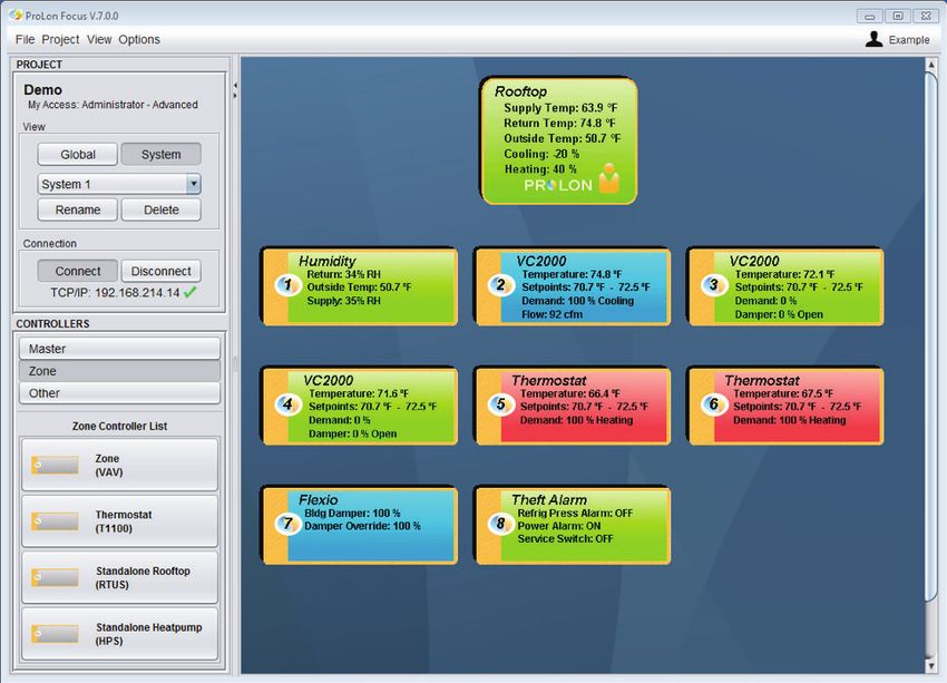
Table of Contents

1 - Prolon Focus Software................................................................................................................................................ 6
      1.1 - Requirements..............................................................................................................................................................................................6
      1.2 - Prolon Cloud Account..............................................................................................................................................................................6
      1.2.1 - Starting Prolon Focus............................................................................................................................................................................7
2 - Screen Tour.................................................................................................................................................................. 9
3 - Network Hierarchy & Navigation............................................................................................................................. 10
      3.1 - System View.............................................................................................................................................................................................. 10
      3.2 - Global View................................................................................................................................................................................................11
4 - Controllers................................................................................................................................................................. 12
      4.1 - Controller Classes.....................................................................................................................................................................................12
      4.2 - Adding Controllers..................................................................................................................................................................................13
      4.2.1 - Best Practice...........................................................................................................................................................................................14
      4.3 - Controller Icons........................................................................................................................................................................................14
      4.4 - Controller Configuration.......................................................................................................................................................................15
      4.4.1 - Home Page & Button..........................................................................................................................................................................15
      4.4.2 - Control Buttons................................................................................................................................................................................... 16
      4.4.3 - Offline Modifications......................................................................................................................................................................... 16
5 - Project Management................................................................................................................................................ 18
      5.1 - Project Administrator.............................................................................................................................................................................18
      5.1.1 - Typical Project Lifecycle......................................................................................................................................................................18
      5.1.2 - Reclaiming Administrator Rights....................................................................................................................................................19
      5.2 - Sharing........................................................................................................................................................................................................19
      5.3 - HVAC Level................................................................................................................................................................................................ 20
6 - Communication......................................................................................................................................................... 21
      6.1 - Serial Connection.................................................................................................................................................................................... 21
      6.2 - TCP / IP........................................................................................................................................................................................................ 21
      6.3 - Modem....................................................................................................................................................................................................... 23
      6.4 - Cloud Communication......................................................................................................................................................................... 23
      6.4.1 - Setting Up Cloud Communication for the First Time............................................................................................................. 24
      6.4.2 - Changing a Claimed Network Controller................................................................................................................................... 25
      6.4.3 - Manually Joining a Project.............................................................................................................................................................. 26
      6.4.4 - Troubleshooting Cloud Communication.................................................................................................................................... 26
7 - Menus & Options....................................................................................................................................................... 28
      7.1 - File Menu.................................................................................................................................................................................................... 28
      7.1.1 - New............................................................................................................................................................................................................ 28
      7.1.2 - Open......................................................................................................................................................................................................... 29
      7.1.3 - Save........................................................................................................................................................................................................... 30
      7.1.4 - Import PRL.............................................................................................................................................................................................. 30
      7.1.5 - Exit............................................................................................................................................................................................................. 30
      7.2 - Project Menu.............................................................................................................................................................................................31
      7.2.1 - Setup.........................................................................................................................................................................................................31

REV 7.3.0 / PL-FOC-FUG-C/F-EN                                                                                                                                                                                                  2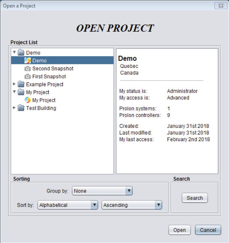
Table of Contents
7.2.1.1 - Description Tab...................................................................................................................................................................................31
7.2.1.2 - Access Tab........................................................................................................................................................................................... 32
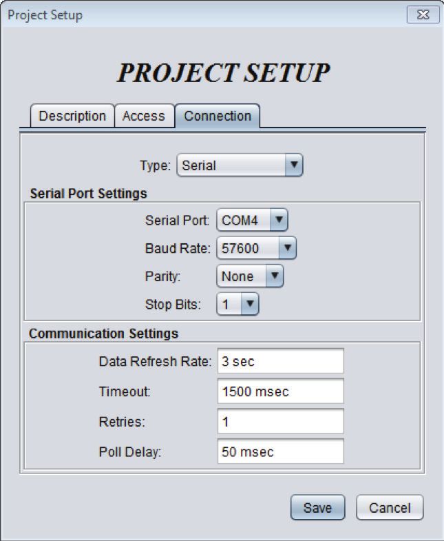
7.2.1.3 - Connection Tab................................................................................................................................................................................. 33
7.2.2 - Participants............................................................................................................................................................................................ 34
7.2.3 - Notes........................................................................................................................................................................................................ 35
7.2.4 - Access Log.............................................................................................................................................................................................. 36
7.2.5 - Snapshot................................................................................................................................................................................................. 37
7.3 - View Menu................................................................................................................................................................................................. 37
7.4 - Options Menu........................................................................................................................................................................................... 37
7.4.1 - Background............................................................................................................................................................................................ 38
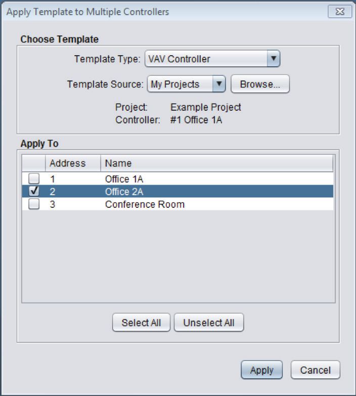
7.4.2 - Apply Template to All......................................................................................................................................................................... 39
7.4.3 - Addressing............................................................................................................................................................................................. 40
7.4.3.1 - Address Management.................................................................................................................................................................... 40
7.4.3.2 - Assign VC2000 Addresses..............................................................................................................................................................41
7.4.4 - Synchronize............................................................................................................................................................................................41
7.4.4.1 - Refresh All............................................................................................................................................................................................41
7.4.4.2 - Discovery............................................................................................................................................................................................. 42
7.4.5 - Reprogram Tool................................................................................................................................................................................... 43
7.4.6 - Advice Upon Config Mismatch....................................................................................................................................................... 44
7.4.7 - Update Software.................................................................................................................................................................................. 45
7.5 - Background Right-Click........................................................................................................................................................................ 45
7.5.1 - Add a Zone / System........................................................................................................................................................................... 45
7.5.2 - Save.......................................................................................................................................................................................................... 45
7.5.3 - Line Up Icons......................................................................................................................................................................................... 46
7.5.4 - Get Names.............................................................................................................................................................................................. 46
7.6 - Profile Management.............................................................................................................................................................................. 46
7.6.1 - Edit Profile.............................................................................................................................................................................................. 47
7.6.2 - Notifications.......................................................................................................................................................................................... 47
7.6.3 - Manage Projects.................................................................................................................................................................................. 48
7.6.4 - Manage User Groups.......................................................................................................................................................................... 49
7.6.5 - Log Out................................................................................................................................................................................................... 49
REV 7.3.0 / PL-FOC-FUG-C/F-EN 3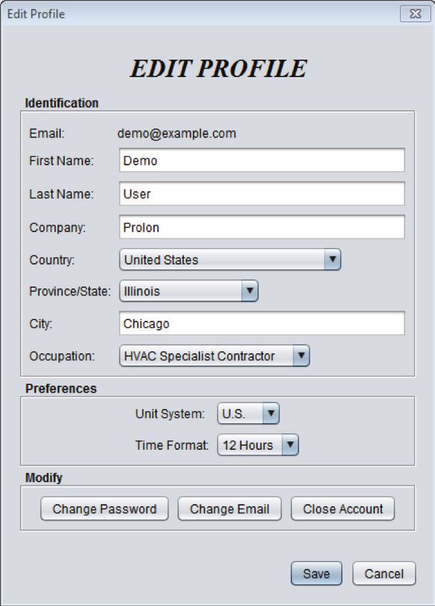
Table of Figures

Figure 1 - Prolon Focus Desktop Icon.................................................................................................................................................................7
Figure 2 - Welcome Screen.....................................................................................................................................................................................7
Figure 3 - Login Dialog Box....................................................................................................................................................................................7
Figure 4 - Start-Up Dialog Box...............................................................................................................................................................................8
Figure 5 - Typical Focus Screen.............................................................................................................................................................................9
Figure 6 - Prolon Network Hierarchy................................................................................................................................................................ 10
Figure 7 - System View.......................................................................................................................................................................................... 10
Figure 8 - Global View.............................................................................................................................................................................................11
Figure 9 - System Icon.............................................................................................................................................................................................11
Figure 10 - Failure to Detect a Controller.........................................................................................................................................................13
Figure 11 - Typical Follower Icon.........................................................................................................................................................................14
Figure 12 - Typical Master Icon............................................................................................................................................................................14
Figure 13 - Icon Minimization..............................................................................................................................................................................15
Figure 14 - Control Buttons.................................................................................................................................................................................. 16
Figure 15 - Offline Modification Marker.......................................................................................................................................................... 16
Figure 16 - Offline Modifications Popup..........................................................................................................................................................17
Figure 17 - HVAC Level Adjustment.................................................................................................................................................................. 20
Figure 18 - Serial Port Connection.................................................................................................................................................................... 21
Figure 19 - TCP/IP Connection.............................................................................................................................................................................. 21
Figure 20 - Forgot Password Button................................................................................................................................................................. 22
Figure 21 - Modem Connection......................................................................................................................................................................... 23
Figure 22 - Modem Dial-Up Screen.................................................................................................................................................................. 23
Figure 23 - Obtaining the NCID (Method 2)................................................................................................................................................... 24
Figure 24 - NCID Popup......................................................................................................................................................................................... 24
Figure 25 - Claiming the Network Controller................................................................................................................................................ 24
Figure 26 - Pasting your NCID............................................................................................................................................................................. 25
Figure 27 - Claim Operations............................................................................................................................................................................... 25
Figure 28 - Join Project Menu............................................................................................................................................................................. 26
Figure 29 - Network Controller Cloud Enable Option................................................................................................................................ 26
Figure 30 - File Menu.............................................................................................................................................................................................. 28
Figure 31 - Open Project Screen........................................................................................................................................................................ 29
Figure 32 - Project Menu.......................................................................................................................................................................................31
Figure 33 - Description Tab...................................................................................................................................................................................31
Figure 34 - Access Tab............................................................................................................................................................................................ 32
Figure 35 - Connection Tab.................................................................................................................................................................................. 33
Figure 36 - Project Participation Screen.......................................................................................................................................................... 34
Figure 37 - Notes Screen....................................................................................................................................................................................... 35
Figure 38 - Access Log Screen............................................................................................................................................................................ 36
Figure 39 - Snapshot Dialog................................................................................................................................................................................ 37
Figure 40 - View Menu........................................................................................................................................................................................... 37
Figure 41 - Options Menu..................................................................................................................................................................................... 37

REV 7.3.0 / PL-FOC-FUG-C/F-EN                                                                                                                                                                                       4
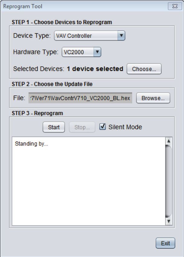
Table of Figures

Figure 42 - Example Background....................................................................................................................................................................... 38
Figure 43 - Background Options........................................................................................................................................................................ 38
Figure 44 - Apply Template to Multiple Screen............................................................................................................................................ 39
Figure 45 - Addressing Menu.............................................................................................................................................................................. 40
Figure 46 - Address Management Screen...................................................................................................................................................... 40
Figure 47 - Synchronize Menu.............................................................................................................................................................................41
Figure 48 - Synchronization Progress Bar....................................................................................................................................................... 42
Figure 49 - Discovery Scan Procress................................................................................................................................................................. 42
Figure 50 - Reprogram Tool................................................................................................................................................................................. 43
Figure 51 - Configuration Mismatch Popup.................................................................................................................................................. 44
Figure 52 - Update Focus Screen....................................................................................................................................................................... 45
Figure 53 - Background Right-Click Popup..................................................................................................................................................... 45
Figure 54 - Profile Management Menu............................................................................................................................................................ 46
Figure 55 - Edit Profile Screen............................................................................................................................................................................. 47
Figure 56 - Message Notification....................................................................................................................................................................... 47
Figure 57 - Message Inbox................................................................................................................................................................................... 48
Figure 58 - Manage User Groups....................................................................................................................................................................... 49

REV 7.3.0 / PL-FOC-FUG-C/F-EN                                                                                                                                                                                5
1 - Prolon Focus Software

Prolon Focus is a powerful configuration and visualization software designed to work with the Prolon controls
system. Every device in the HVAC system can be configured and optimized while being constantly monitored for
maximum performance and energy savings. It can communicate with a project over various media ranging from
local serial connections to remote, Cloud-based networks.

1.1 - Requirements

Operating System
  • Windows Vista, 7, 8, 10
  • Mac OS X 10.8 or higher (Please note that all images in this documents are from Windows and their appearance
		 may differ slightly on macOS)

Java
   • 1.8 and above (32-bit version required for Windows)

Keep your Focus version up to date by visiting our website (www.proloncontrols.com) or by making use of the Update
Software feature of Prolon Focus.

1.2 - Prolon Cloud Account

The Prolon Cloud is an online service used to store all your Prolon projects, settings and more. With your Cloud account
you can:

   • Easily share your projects and settings between your mobile devices and computers
   • Communicate to the project via Cloud Communication (if Network Controller is present)
   • Grant project access to colleagues, contractors or specialists, and revoke it at any time
   • Ensure your projects are up to date, regardless of modifications from other users
   • Take snapshots of the current state of your project for future reference
   • Get notifications about any changes other participants make to your project
   • View important project notes left by yourself or other participants
   • Rest assured knowing all data is securely stored on Google-backed servers with daily backups

You can sign up for your FREE Prolon Cloud account anytime using the Prolon Focus software. An internet connection is
required to sign into your account and access all these features.

Please note that a Prolon Cloud account is optional, and therefore not necessary to use the Prolon Focus software. A
guest account can be used anytime, allowing for local access to a project in case no internet access is available. Project
data can be stored in a local file for recovery later.

REV 7.3.0 / PL-FOC-FUG-C/F-EN                                                                                           6
1.2.1 - Starting Prolon Focus

1) To start the Prolon Focus software, double-click the Prolon Focus icon on your desktop:

                                           Figure 1 - Prolon Focus Desktop Icon

2) Upon start-up, you are greeted with a Welcome screen. From here you can decide whether to log in to your Cloud
   account, or to continue as a Guest. Note that if you do not have internet access, you will immediately be logged in as
   a Guest (see below).

                                                Figure 2 - Welcome Screen

• Log in to my Cloud account: Use this to proceed to            • Continue as Guest: If you do not yet have a Prolon
  the Login screen in part 3) below. See Section 1.2 - Prolon     Cloud account or cannot access the internet at this
  Cloud Account for more info about Cloud Accounts.               time, you can continue using Prolon Focus as a guest.

                                                                     While working as a guest, you can still connect to your
                                                                     project using local means (Serial port / USB) or remotely
                                                                     when available (TCP/IP over port 502, Modem), but you
                                                                     cannot communicate to your project using Prolon
                                                                     Cloud Communication.

                                                                     Also, any project you build while in guest mode will
                                                                     need to be saved to a local file (PRL file) if you wish to
                                                                     recover it later. Note that PRL files can be imported as
                                                                     projects into Focus and stored to your Cloud account
                                                                     the next time you log in.

3) This screen is used to login to your free Prolon Cloud account.

                                                Figure 3 - Login Dialog Box

• New Account: If you do not yet have a Prolon Cloud            • Forgot Password: If you forget your password, Focus
  account, this button launches the account creation              will send you a temporary password via email that can
  screen.                                                         be used to login and update your account password.

REV 7.3.0 / PL-FOC-FUG-C/F-EN                                                                                                7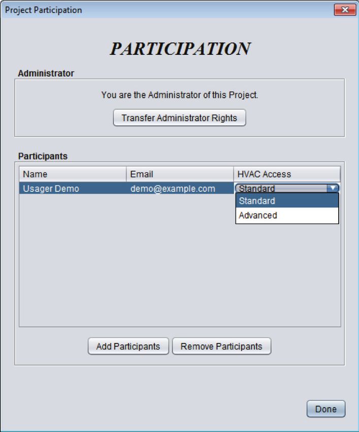
• Log In: After providing your credentials, you are logged
  into your Cloud account, and will be directed to the
  Welcome screen below.

4) Finally, you are presented with the Start-Up screen, prompting you for the desired project you wish to open.

                                              Figure 4 - Start-Up Dialog Box

• Create a new project: Starts an empty project. All           • Open last project: Instructs Focus to open the Prolon
  controllers must be added to the screen from scratch.          project that was last used. Gives you quick access to
  Use this for new jobs (start-ups) or for testing purposes.     your last project.

• Open existing project: Browse your Cloud account                Note that if you simply wish to import an existing PRL
  for an existing Prolon project that you wish to open.           file from your computer, choose the option: “Create a
  (See Open).                                                     new project”, and proceed to the Import PRL menu.

REV 7.3.0 / PL-FOC-FUG-C/F-EN                                                                                         8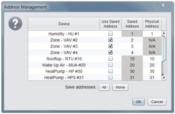
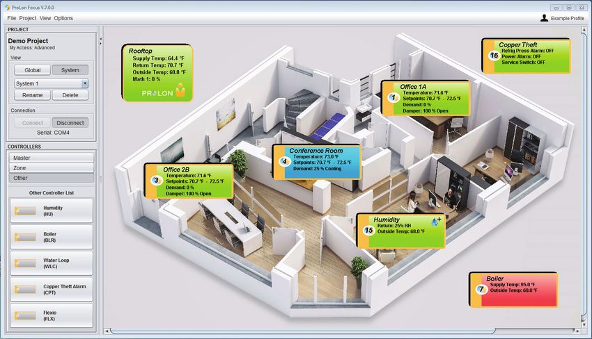
2 - Screen Tour

The following is a screenshot from a typical Prolon project:

   1
   2                                                                               13

   3                                                       11
   4

   5
   6

                                      12
   7
   8

   9

  10

                                                 Figure 5 - Typical Focus Screen

1.		    Title Bar (Displays the current Focus version)
2.		 Menus & Options
3.		 Project Name
4.		 Project Access Level
5.		 Global View & System View Toggle Buttons
6.		 System Select Dropdown List
7.		    Connect & Disconnect Toggle Buttons
8.		 Connection Status
9.		    Device Category Selection
10.     Device Buttons (Drag and Drop)
11.		   Master Icon
12.		   Follower Icons
13.     Profile Management

REV 7.3.0 / PL-FOC-FUG-C/F-EN                                                           9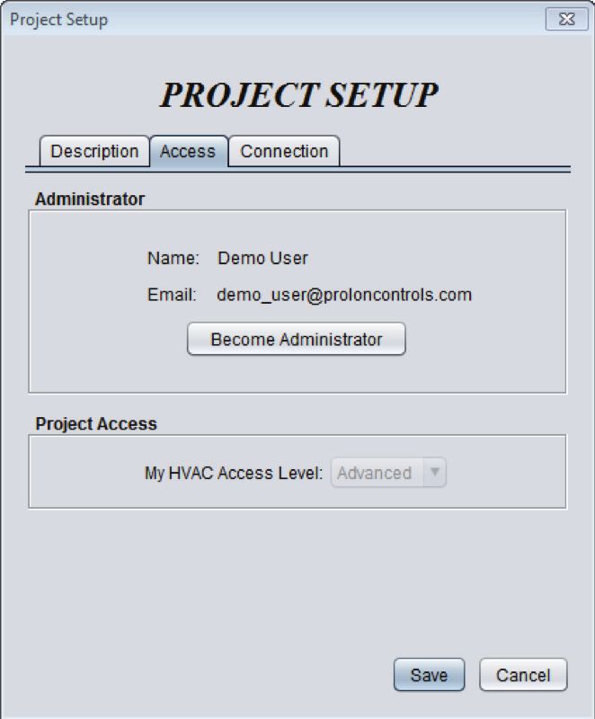
3 - Network Hierarchy & Navigation

A typical Prolon Network can be seen as a simple hierarchy. A Network Controller is at the peak of the hierarchy, presiding
above Prolon Master controllers, such as a Zoning Rooftop or Zoning Heatpump controllers. Then, below each Master are
the Follower controllers. Follower controllers can only be associated with a single Master:

                                                       Network Controller

                                     Master A              Master B            Master C

                                    Follower A1           Follower B1         Follower C1

                                    Follower A2                               Follower C2

                                                                              Follower C3

                                          Figure 6 - Prolon Network Hierarchy

This hierarchy is also present in the way Prolon Focus is designed to display your project. There are two types of views:
a “System” view and a “Global” view. You can flip between each view using the Global / System toggle buttons or using
the View Menu.

3.1 - System View

The System view displays a single branch within the network:

                                                         Network Controller

                                        Master A              Master B           Master C

                                      Follower A1           Follower B1         Follower C1

                                      Follower A2                               Follower C2

                                                                                Follower C3

                                                    Figure 7 - System View

This branch shows a single Master controller with its associated follower controllers. You can switch between the different
Systems using the System Select Dropdown list.

Note that a system does not necessarily require a Master controller: it can simply be a collection of follower controllers.

REV 7.3.0 / PL-FOC-FUG-C/F-EN                                                                                            10
3.2 - Global View
The Global view displays the highest network hierarchy level:
Network Controller
Master A Master B Master C
Follower A1 Follower B1 Follower C1
Follower A2 Follower C2
Follower C3
Figure 8 - Global View
It displays the Network Controller and all the Master controllers. If a particular system does not have a Master controller,
then that system will instead be represented by a generic icon that displays the quantity of controllers within that system:
Figure 9 - System Icon
Double-clicking a Master or generic System icon will immediately switch you to the System View of that system.
Note that a Network Controller is not required for Focus to show the Global view. It will instead simply show all available
Masters or Systems.
More Systems can be added to a project by clicking or dragging the “New System” button from the Drag & Drop section
on the left side of the screen. Systems are empty by default.
REV 7.3.0 / PL-FOC-FUG-C/F-EN 114 - Controllers
The purpose of the Prolon Focus software is to provide information about the various controllers in your
building. This section describes how to add controllers to your project and provides general information about
viewing and modifying their configuration.
Please note that a detailed look at the settings and sequences of each controller is beyond the scope of this
document. Please refer to each controller’s respective Focus Guide for more details.
4.1 - Controller Classes
There are two controller classes in Prolon Focus:
• Master Controllers
• Follower Controllers
In a single System, there can be many Follower Controllers but only a single Master Controller.
A Master Controller exchanges information with its Follower Controllers to achieve a better overall control strategy. In
contrast, Follower Controllers will never directly talk to one another. They rely on the Master for any type of data ex-
change. A Follower Controller can only belong to a single Master. These dynamics are derived from Modbus, the commu-
nication protocol on which Prolon controllers are based. Note that Follower controllers can still operate in the absence of
a Master, except they will be working with less information.
The following table lists all Controllers currently available:
FOLLOWER
MASTER
ZONE OTHER
Zoning Rooftop (RTU) VAV Zone (VAV) Humidity (HUM)
Zoning Heatpump (HP) Thermostat (T1100) Boiler (BLR)
Hydronics (HYD) Single-Zone Rooftop (RTUS) Water Loop (WLC)
Make Up Air (MUA) Single-Zone Heatpump (HPS) Copper Theft Alarm (CPT)
FlexIO (FLX)
Finally, all Prolon Controllers (Master or Follower) can be united under a Network Controller. There can only be a single
Network Controller in an entire Prolon project. It traditionally acts as a gateway to the internet, but also serves in data
logging and email alert capacities.
REV 7.3.0 / PL-FOC-FUG-C/F-EN 124.2 - Adding Controllers
When connecting to a new project for the first time, Prolon controllers will need to be added to the Focus project sys-
tematically under the direction of the user; Prolon Focus does not have any kind of general purpose detection feature
to do this automatically due to the uncertain state of the communication bus during a job start-up. However, once the
controllers are added the first time and the project is saved, they will be loaded automatically next time.
Controllers can be added manually to the project using the Drag & Drop buttons on the left side: You can drag a control-
ler out from the left and drop it anywhere on the screen, or simply click the button and Focus will place it for you. The
only information required is the Modbus address of the controller. The source of this address varies by controller; please
refer to the respective controller’s Focus guide for more details. Controllers can be addressed in the range of 1 to 127.
• Note 1: No two controllers (Master or Follower) should • Note 2: When a Follower controller belongs to a Master
share the same Modbus address, regardless of where controller, the Master controller acts like a router, and
they are found in the network hierarchy. This will create must be aware of the Follower controller before allowing
an address conflict, disrupting the normal flow of com- any messages to reach it. In other words, you will not
munication. be able to manually add a Follower controller to a project
if the Master does not yet know it exists. A Master peri-
odically updates its list of followers, but you can force it
do so manually by cycling power, or by performing a
Get List (as described below).
There are other methods of adding controllers to a project, including the “Get List” method (found when right-clicking a
Master icon) or the “Add Multiple” method (found when right-clicking the Drag & Drop button of the Zone Controllers).
These are discussed in greater detail in the respective Focus guide of each controller.
If Focus cannot detect the controller, a warning message will appear, and the controller will not be added to the project.
Verify the wiring and controller addressing and try again.
Figure 10 - Failure to Detect a Controller
Once the controller is added and detected by the Focus software, an icon is created representing that controller. You can
move the icons around the screen as desired.
Once a Master icon is added to a System, you may notice that the other Master Drag & Drop buttons become unavailable
for that system. This is consistent with the limitations of Master controller classes, as described above.
REV 7.3.0 / PL-FOC-FUG-C/F-EN 134.2.1 - Best Practice
This section details the most efficient way of building a typical Prolon project, consisting of one or multiple Masters, each
with Follower Controllers of their own:
1. While in System View (the default view when starting a project), add your first Master Controller to the project using
the Drag & Drop buttons on the left side of the screen. You will need to know the address of this Master Controller.
2. Right-click the newly-created Master Controller icon and select “Get List”. The Master Controller searches its network
and will create icons for any Follower Controllers that are discovered. (You do not need to provide any information for
a “Get List”).
3. If you have other Master controllers to add, switch to Global View and add a new System using the Drag & Drop but-
tons on the left. Otherwise, go to step 7. You will be prompted to name this new system.
4. Double-click the newly-created System icon. You are brought to the System view for this new system. Since it is a new
system, it is normal that it will be empty.
5. Repeat steps 1 and 2 for this new Master and its respective Followers.
6. Repeat steps 3 to 5 for any other systems.
7. If applicable, add your Network Controller in Global View.
8. Synchronize your project’s database by performing a “Refresh All”
9. Once all controllers in the project show up and are communicating, save your project.
If a particular system does not have a Master controller and is comprised entirely of Follower controllers, they will just
have to be added manually using the Drag & Drop buttons on the left.
4.3 - Controller Icons
Each Controller class described above has its own type of icon:
Figure 11 - Typical Follower Icon Figure 12 - Typical Master Icon
(These icons are loosely portrayed in the respective Drag & Drop button for each controller, giving a quick way to discern
the controller class of each device).
REV 7.3.0 / PL-FOC-FUG-C/F-EN 14Icons show data about the controller they represent, offering a way to assess the status of your project at a quick glance.
The information shown in the icons gets updated periodically (see Refresh Rate in the Connection Tab). The color of the
icons is also significant: blue means that the controller is cooling, red is heating, green is satisfied, and gray is offline.
Icons can be moved around the screen by clicking and dragging them to the desired location. This can be of interest
when using a background.
Finally, Follower icons can be minimized to reduce screen clutter. To minimize a Follower icon, click on the Prolon Yin-
Yang symbol. Click it again to return to normal size:
Click on the Prolon circle
to minimize the icon
Figure 13 - Icon Minimization
When Follower icons are minimized, they are highlighted with the same color that represents the current action of the
controller, as described above.
4.4 - Controller Configuration
The configuration of each controller can be accessed by double-clicking its associated icon. A configuration screen
dedicated to that specific controller subsequently opens.
A detailed look at every setting of each controller is beyond the scope of this document (please refer to each controller’s
respective Focus Guide for these details). Instead this document will focus on the common elements of configuration
shared between all controllers.
4.4.1 - Home Page & Button
When a configuration screen is opened, Focus first presents the Home page. In essence, the Home page is a detailed
status page, displaying all possible information about the inputs, outputs and actions that the controller is currently
taking. It is all visualized using a series of icons and graphics representing a typical setup for that controller. The graphics
can vary based on the chosen configuration of that controller.
All controllers have a Home page, which is also used to perform overrides on the outputs of the controller. The configu-
ration screen even has a permanent “Home” button at the top right to instantly bring up the Home screen when needed.
REV 7.3.0 / PL-FOC-FUG-C/F-EN 154.4.2 - Control Buttons
All controller configuration screens have the following three control buttons in the bottom right corner:
Figure 14 - Control Buttons
• Refresh: Forces the Focus software to read all configu- • Exit: Closes the configuration screen. If any change is
ration data from the controller and display it on screen. made to the configuration that has not yet been ap
By default, this automatically happens anytime the plied, the change will be lost (similar to a “Cancel” button).
configuration screen is opened, but this button can be Note that if there are any overrides active on the control
useful for debugging purposes, or to see if recent (damper, outputs, etc.) you will be given the option to
changes to the controller’s configuration were successful. remove the overrides at this point.
• Apply: Causes the Focus software to send the current Note: These buttons are not visible when the Home
configuration shown on screen to the controller. This Page is being displayed (they have no effect on the
command message will be sent regardless of whether Home Page data, so they are hidden from view). They
or not any changes were made on screen. Note that will be visible in every other page in the configuration
before the message is sent, the Focus software will vali- screen.
date the configuration, warn you if any irregularities
are found and suggest how to correct them.
4.4.3 - Offline Modifications
The Prolon Focus software can be run in Offline mode. In Offline mode, the configuration page of each controller can
still be edited just like in online mode, but the actual controller will not receive these new settings until you return online.
When a change is made to a controller’s configuration in Offline mode, a small asterisk will be placed after the controller’s
name on its icon:
Figure 15 - Offline Modification Marker
This asterisk acts as a reminder that the configuration of this controller has been changed in Offline mode, and that an
action from you is required before it can be sent to the controller.
When online, double-click the controller to open the configuration screen. You will be prompted to make a choice re-
garding the offline modifications:
REV 7.3.0 / PL-FOC-FUG-C/F-EN 16Figure 16 - Offline Modifications Popup
• View Offline Configuration: Allows you to review the • Retrieve Current Configuration from this device: If
setup you had created offline before applying it to the you are curious as to the configuration currently in the
controller. Once you are satisfied, press the Apply but- device, you can view that with the third option. Note
ton to confirm. Only after pressing the Apply button will that this will not discard your offline configuration:
the asterisk be removed. the asterisk remains so long as the Apply button is not
pressed. To view your offline configuration again, exit
• Apply Offline Modifications and Open: Focus will the configuration screen without pressing the Apply
apply the offline configuration immediately. This will button, and then re-enter the configuration screen.
remove the asterisk automatically.
REV 7.3.0 / PL-FOC-FUG-C/F-EN 175 - Project Management In Prolon Focus, a project represents the network of Prolon controllers in a building. The ability to remotely access and view the project is controlled by a project administrator. 5.1 - Project Administrator For every Prolon project, there is an administrator. The administrator’s primary role is to decide who has remote access to the project and what each participant’s HVAC level is. Typically, the administrator is the owner or primary maintenance technician of the building. The administrator controls the project’s visibility on the Cloud, as well as any Cloud-based communication to the pro- ject (see Cloud Communication). The administrator also controls the ability to delete project notes. It is important to note that if a person (participant or not) has the means to locally access the controllers (in other words, physically connect to them inside the building), there is nothing preventing them from creating a new project and working on them locally. However, they will not be able to continue their work remotely without the administrator’s permission. 5.1.1 - Typical Project Lifecycle When a project is first created, the initial creator is automatically set as the administrator. This could be a contractor who has been charged with installing and commissioning Prolon controllers in a building. During the installation phase, the contractor may choose to share the project with colleagues or employees for easier servicing. When the project is finally ready for delivery, the contractor will typically transfer the administrator rights to the client or end-user. The client can then adjust the list of participants at their discretion. Before handing over the administrator rights, the contractor can take a snapshot of the project. This snapshot can be useful for future reference, detailing the state of every controller in the project as it was delivered. Snapshots belong to the user who took them and remain in their possession even if the administrator removes their access (see Snapshot). Over time, project administrators can grant or revoke access to various contractors and specialists as required for ser- vicing and maintenance. If building ownership ever changes hands, the administrator should transfer their rights to the appropriate party. If the Prolon account containing the administrator rights to a project is forgotten or otherwise unob- tainable, the procedure below outlines the steps for reclaiming those rights. REV 7.3.0 / PL-FOC-FUG-C/F-EN 18
5.1.2 - Reclaiming Administrator Rights

Should the administrator of a project become unavailable, a new administrator can be assigned. The exact method to
reclaim the administrator rights will depend on the presence of a Prolon Network Controller, but always requires local,
physical access to the controllers (i.e. must be in the building) and cannot be done remotely. Note: A TCP/IP connection
also counts as a local connection and can be used for this purpose.

If the project contains a Prolon Network Controller:
The process differs slightly depending on whether or not you are already a participant in the project. If you are NOT:
the Prolon Focus software can determine which Cloud project is associated to a given Network Controller and can add
a local user to that project. Follow the steps in Section 6.4.3 -Manually Joining a Project to add yourself to the project
participation list.

Once you are a participant, follow the steps in Section 7.2.1.2 - to become administrator.

If there is no Prolon Network Controller in the project:
A new project can simply be built to replace the old one. Connect to the project using local means and make use of the
Get List function available on any Prolon Master controllers to speed up this process (see section 4.2.1 - Best Practice).
You will have access to all the settings in every controller.

5.2 - Sharing

Prolon projects can be shared by the administrator to anyone who has a Prolon Cloud account (free). Sharing a project
to other users allows them to:
   • View the project and change settings (as far as their HVAC level allows them)
   • Communicate with the project via Cloud Communication (if a Network Controller is present)
   • Add notes to the project
   • Take snapshots of the project

When the project is shared, the receiver will get a message in their Focus Inbox and the project itself will become avai-
lable in their Open Project dialog. Any changes made to the controllers of a project by the administrator or the partici-
pants are noted in the project Access Log.

Note that the administrator can revoke any participant’s access at any time, but the participant gets to keep any snap-
shots that they have been shared or that they have created on their own. Any logs or notes contributed by the removed
participant remain attached to the project.

Projects can be shared to individual users one at a time by providing their email, or they can be shared instantly to a
whole group (see Manage User Groups).

REV 7.3.0 / PL-FOC-FUG-C/F-EN                                                                                          19
5.3 - HVAC Level

The project administrator assigns the HVAC level of all project participants. HVAC access levels determine the type
of information a participant can see and change in the project. There are currently two access levels in Prolon Focus:
Advanced and Standard.

The Advanced level unlocks all functionalities in the Focus software and lets the user view and configure any setting of
any controller. (This is the default level assigned to you when creating a new project).

The Standard level grants basic access to the project: users can see the controller icons, backgrounds and be able to
access the Home Page of a controller’s configuration screen. However, they are blocked from accessing any of the con-
figuration pages or from performing overrides to the controller’s outputs. This prevents them from changing any of the
configuration settings in any given controller.

There are a few exceptions. Users with Standard access can still adjust the following settings:
   • Zone Default Heat Setpoint
   • Weekly Schedules
   • Holiday Calendar
   • Zone Minimum Deadband
   • Zone Setpoint Limits
   • Zone Unoccupied Mode Limits and Offsets
   • Zone Unoccupied Mode Override Time

These basic settings are less critical and are often required to be adjusted periodically.

The administrator can change any user’s HVAC level at any time by heading to the Access Tab screen and individually
adjusting the setting in the third column of the participants list.

                                            Figure 17 - HVAC Level Adjustment

The administrator also has the opportunity to set participants HVAC levels at the moment projects are initially shared to
them.

REV 7.3.0 / PL-FOC-FUG-C/F-EN                                                                                         20
6 - Communication
Prolon Focus offers various methods to communicate to the controllers in a building, ranging from serial, wire-
less and remote cloud access over the internet.
Select the communication method in the Connection Tab.
6.1 - Serial Connection
Select this local communication option when you are using an RS485 converter or other serial method, such as USB
through the Prolon Network Controller (look for the serial port marked “USB”).
Figure 18 - Serial Port Connection
If the drop-down list of serial ports is empty, this indicates that your computer is not aware of any modules or peripherals
that can act as a serial port. If this is the case, ensure that the proper drivers are installed for your peripheral and that your
peripheral is properly connected to your computer, and then close and re-open the Focus software.
The Baud Rate, Parity and Stop Bits are configurable serial settings, but in standard Prolon networks, they are not usually
changed and should remain at their default values: 57600 baud, no parity, and one stop bit.
6.2 - TCP / IP
This option is used when connecting locally or remotely to a Prolon Network Controller (or other Modbus TCP server)
over its Ethernet port.
Figure 19 - TCP/IP Connection
Prolon Focus can remember two IP addresses for the same project. This can be useful when there is an IP address that
works from inside the building, but an external one is required when working remotely.
By default, Prolon Focus will attempt to connect to the specified IP address by opening port 502 (the default port for
Modbus communication).
REV 7.3.0 / PL-FOC-FUG-C/F-EN 21You can also read