M1 Garand Operation, Safety, and Maintenance Guide for Veteran and Civilian Service Organizations, Law Enforcement, and National Cemeteries
←
→
Page content transcription
If your browser does not render page correctly, please read the page content below
M1 Garand Operation, Safety, and Maintenance Guide
                       for
   Veteran and Civilian Service Organizations,
             Law Enforcement, and
              National Cemeteries
                                 21 January 2020 – Change 4

                                         Prepared by
                 Combat Capabilities Development Command Armaments Center
                        (CCDC-AC) Picatinny Arsenal, NJ 07806-5000

      DISTRIBUTION STATEMENT A. Approved for public release: distribution is unlimited.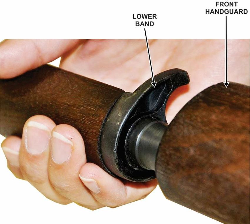
DISCLAIMER STATEMENT

This guide is intended to support the safe operation and maintenance of the M1 Garand Service Rifle and .30 Caliber M1909 Blank
Ammunition being used by Veteran and Civilian Service Organizations, Law Enforcement, and National Cemetery Personnel
approved to receive both M1 Garand Rifles and .30 Caliber Blank Ammunition from the U.S. Government. It is not intended as a
guide for the general public. While the Combat Capabilities Development Command Armaments Center strives to make the
information contained in this guide as accurate as possible, CCDC-AC makes no claims, promises, or guarantees about the accuracy,
completeness, or adequacy of the contents of this guide, and expressly disclaims any liability for errors and omissions pertaining to
its contents. No warranty of any kind, implied, expressed, or statutory is given with respect to the contents of this guide or any links
to internet resources contained herein. References in this guide to any specific commercial product, process, or service, or the use of
any trade, firm, or corporation name is for information purposes only and does not constitute endorsement, recommendation, or
favoring by the Combat Capabilities Development Command Armaments Center or the United States Government.

M1 Garand Operation and Maintenance Guide - 2
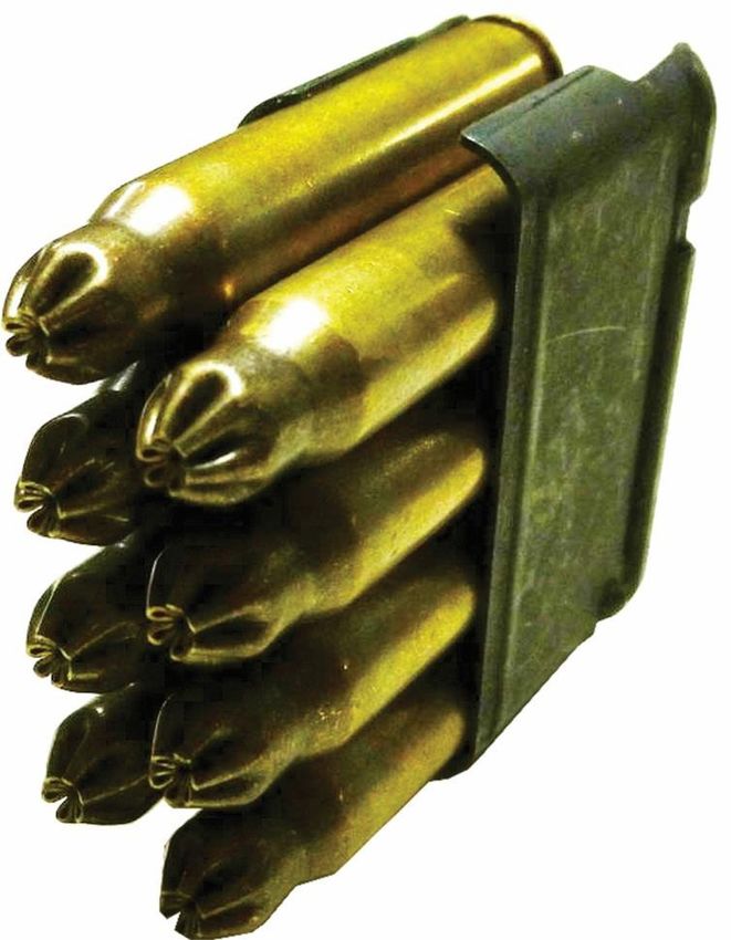
Table of Contents

1.0 Introduction ......................................................................................................................................................................................... 6
   1.1 Purpose and Scope ............................................................................................................................................................................ 6
   1.2 Importance of this Guide .................................................................................................................................................................. 7
   1.3 General Description of the Rifle ....................................................................................................................................................... 7

2.0 Mechanical Training........................................................................................................................................................................... 7
   2.1 Required Tools .................................................................................................................................................................................. 7
   2.2 Disassembly and Assembly Overview.............................................................................................................................................. 7
   2.3 Unloading and Clearing the Rifle ..................................................................................................................................................... 8
   2.4 Disassembly into Three Main Groups ............................................................................................................................................ 10
   2.5 Barrel and Receiver Group – Disassembly of the Operating Mechanism ...................................................................................... 12
   2.6 Barrel and Receiver Group – Assembly of the Operating Mechanism .......................................................................................... 19
   2.7 Assembly of the Three Main Groups .............................................................................................................................................. 29
   2.8 Blank Firing Adapter (BFA) ........................................................................................................................................................... 30
   2.9 Test for Correct Assembly .............................................................................................................................................................. 30

3.0 Operation and Functioning .............................................................................................................................................................. 30
   3.1 Loading Rounds into a Clip ............................................................................................................................................................ 30
   3.2 Loading the Rifle ............................................................................................................................................................................ 31
   3.3 Unloading the Rifle (not due to a misfire) ...................................................................................................................................... 32
   3.4 Functioning of the Rifle .................................................................................................................................................................. 32

4.0 Stoppage, Immediate Action, Malfunctions, and Ammunition Malfunction Reporting ............................................................ 34
   4.1 Immediate Action ........................................................................................................................................................................... 34
   4.2 Malfunctions ................................................................................................................................................................................... 34
   4.3 Ammunition Malfunction Reporting .............................................................................................................................................. 37
M1 Garand Operation and Maintenance Guide - 3
5.0 Maintenance ...................................................................................................................................................................................... 37
   5.1 Cleaning Materials, Lubricants, Equipment, and Parts .................................................................................................................. 37
     5.1.1 Cleaning Solutions ................................................................................................................................................................... 37
      5.1.2 Lubricants ................................................................................................................................................................................ 37
     5.1.3 Equipment ................................................................................................................................................................................ 38
   5.2 Cleaning the Rifle ........................................................................................................................................................................... 38
     5.2.1 Chamber ................................................................................................................................................................................... 38
     5.2.2 Bore .......................................................................................................................................................................................... 39
     5.2.3 Gas Cylinder Lock Screw Assembly ....................................................................................................................................... 39
     5.2.4 Piston Operating Rod ............................................................................................................................................................... 39
     5.2.5 Gas Cylinder ............................................................................................................................................................................ 39
     5.2.6 Face of the Bolt ........................................................................................................................................................................ 39
     5.2.7 Rifle Stock................................................................................................................................................................................ 39
     5.2.8 All Other Parts ......................................................................................................................................................................... 40
   5.3 Routine Maintenance ...................................................................................................................................................................... 40
     5.3.1 Daily Inspection ....................................................................................................................................................................... 40
   5.4 Blank Firing Adapter/Barrel Inspection Criteria ............................................................................................................................ 40
     5.4.1 BFA Inspection ........................................................................................................................................................................ 40
     5.4.2 Barrel Thread Inspection.......................................................................................................................................................... 44

6.0 Ceremony Planning and Safety Guidance ...................................................................................................................................... 47
   6.1 Ceremony Planning......................................................................................................................................................................... 47
   6.2 Hearing Protection .......................................................................................................................................................................... 48
   6.3 Standoff Distance ............................................................................................................................................................................ 48
   6.4 Expended Brass............................................................................................................................................................................... 48

7.0 Ammunition ....................................................................................................................................................................................... 48
   7.1 Ammunition Safety Warnings ........................................................................................................................................................ 48
   7.2 Ordering Ammunition..................................................................................................................................................................... 49
   7.3 Authorized Ammunition ................................................................................................................................................................. 50

8.0 Physical Security and Inventory Requirements ............................................................................................................................. 51

M1 Garand Operation and Maintenance Guide - 4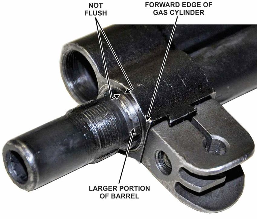
8.1 Rifle and Ammunition– Physical Security and Inventory Requirements ....................................................................................... 51

9.0 Comments, Questions, and Suggestions .......................................................................................................................................... 52

Appendix A: Safety Area Template ..................................................................................................................................................... 53

Appendix B: Ceremonial Rifle Inventory Form ................................................................................................................................. 54

M1 Garand Operation and Maintenance Guide - 5
any firearm, if any operation of the M1 Garand Rifle seems questionable
1.0 Introduction                                                      or out of the ordinary, bring the weapon to a competent professional for
                                                                      servicing.
1.1 Purpose and Scope
                                                                      The Corporation for the Promotion of Rifle Practice and Firearms
Although the M1 Garand Rifle is no longer actively used by            Safety, Inc. (CPRPFS):
the U.S. Military, Public Law 106-65 (10 USC 7683) allows
for the conditional donation by the U.S. Government of .30            The Corporation for the Promotion of Rifle Practice and Firearms
Caliber M1 Garand Rifles to eligible organizations for use by         Safety, Inc. (Civilian Marksmanship Program (CMP)) is the
those organizations in the rendering of funeral honors for a          organization designated by the U.S. Government with providing
member or former member of the U.S. Armed Forces and for              weapon support, including parts replacement information, and
general ceremonial purposes. The M1 Garand is currently the           weapon maintenance training to law enforcement, civilian and
only ceremonial rifle being conditionally donated. The number         veteran service organizations, and national cemeteries that are
of conditionally donated ceremonial rifles (both bolt-action          furnished with M1 Garand Rifles. In addition, they assist with the
and the M1 Garand) in possession by any eligible organization         reporting and onsite data collection for malfunctions. They can be
cannot exceed 15 (fifteen). Rifles in excess of 15 must be            contacted at: Civilian Marksmanship Program, 1401 Commerce
turned in. The replacement or exchange of ceremonial rifles is        Blvd., Anniston, AL 36207 Tel. 256-835-8455/Fax. 256-835-3527,
authorized on a one-for-one basis if the ceremonial rifle             www.thecmp.org.
becomes unserviceable. Ceremonial rifles remain the property
of the United States Government. The recipient organization is        In the event of an ammunition malfunction contact the U.S.
not authorized to use the rifle as security for any loan, nor sell,   Army Joint Munitions Command (JMC):
lease, rent, or exchange the property for monetary gain or for        Ammunition Surveillance Division (AMSJM-QAS)
any other purpose. Nor is the recipient organization authorized       2695 Rodman Ave
to transfer, relocate, or dispose of the asset without written        Rock Island, Illinois 61299-6000
approval from the Army Donations Program Office.                      DSN 793-7295
The storage of the ceremonial rifles is at the discretion of          COMM 309-782-7295
your organization as long as you comply with local, state, and        FAX 309-782-7136
federal guidelines for firearms.                                      usarmy.ria.jmc.mbx.amsjm-qas@mail.mil

The Ceremonial Rifle Form, which is the document                      Mailing Address:
organizations use for their required reporting to the US Army         U.S. Army Joint Munitions Command, AMSJM-QAS
ceremonial rifles in their possession every three years, is           2695 Rodman Ave, Rock Island, IL 61299-6000
included in Appendix B.                                               For comments, suggestions, or questions concerning this
This document should be used as a guide by these                      guide contact the U.S. Combat Capabilities
nonmilitary organizations for the maintenance, operation, and         Development Command Armaments Center (CCDC-
general information relating to the M1 Garand Rifle. As with          AC):

M1 Garand Operation and Maintenance Guide - 6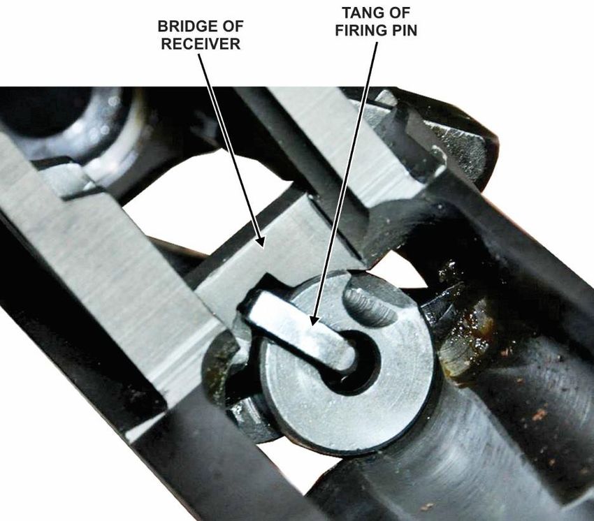
Telephone: 973-724-3056
Fax: 973-724-4633                                                 1.3 General Description of the Rifle
E-mail: usarmy.ccdc-ac.pica2028@mail.mil
Website:http://www.m1garandtraining.com                           The U.S. Rifle Caliber .30, M1 Garand, is an air cooled, gas operated, en-
Mailing Address:                                                  bloc clip-fed, semiautomatic shoulder fired weapon. This means that air
U.S. Army CCDC-AC Attn: FCDD-ACE-LL                               cools the barrel; that the power to cycle the action comes from gas pressure
Picatinny Arsenal, NJ 07806-5000                                  created by the firing of each round; that it is loaded by inserting a metal en-
                                                                  bloc clip into the receiver; and that the rifle fires one round each time the
                                                                  trigger is pulled.
Rifle Authorizations and Turn-In:
For recognized Veteran Service Organizations regarding issues
                                                                  2.0 Mechanical Training
concerning M1 Garand Rifle authorizations for new issue or
for equipment turn in, please contact your organization’s         2.1 Required Tools
National Headquarters. Information concerning the U.S. Army
Donations Program is also contained in your organization’s           •   T-grip flathead screwdriver (preferred) or regular
officer’s guide. For other organizations, such as law                    flathead screwdriver.
enforcement, contact the U.S. Army Donations Program Office
located in Detroit Arsenal, MI at                                    •   1/8-inch punch or similar object
usarmy.detroit.tacom.mbx.ilsc- donations@mail.mil,                   •   7/16-inch wrench or adjustable wrench
(586) 282-9861.
                                                                     •   Wooden mallet
Mailing Address:
US Army Tank-automotive and Armaments Command                     2.2 Disassembly and Assembly Overview
(TACOM)                                                           The rifle should be disassembled and assembled only when
ATTN: AMSTA-LCL-IWD, M/S 419D                                     maintenance is required or for instructional purposes.
6501 East 11 Mile Road                                            Repeated disassembly and assembly causes excessive wear and
Detroit Arsenal, MI 48387-5000                                    tear of parts and increases the frequency of weapon failure/part
                                                                  replacement.
1.2 Importance of this Guide
                                                                  The rifle has been designed so that it may be disassembled and
In order to minimize weapon failures and increase safety, it is
                                                                  reassembled easily. With the exception of the bolt, the parts of
important for each operator to know the working parts and
                                                                  one rifle may be interchanged with those of another rifle, when
proper operation and maintenance of the weapon. Procedures
                                                                  necessary. For safety reasons, bolts should never be
other than those described herein should not be performed
                                                                  interchanged except by designated representatives of CMP.
without consulting CMP.
                                                                  To make assembly easier, the parts should be laid out on a
WARNING: Severe weapon damage and/or injury may
                                                                  clean flat surface, from left to right, in the order of removal as
occur if the weapon is not maintained and operated
                                                                  the rifle is disassembled.
properly.
M1 Garand Operation and Maintenance Guide - 7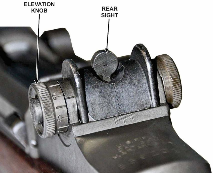
2.3 Unloading and Clearing the Rifle
                                                                    To clear the rifle, pull the operating rod handle all the way to
The first step in handling any weapon is to unload and clear it.    the rear (make sure that the bolt is fully rearward and not
To unload a round from the chamber, support the rifle; with the     caught on the follower assembly (figs 3 and 4)) and inspect the
right hand grasp the operating rod handle and pull the operating    chamber and receiver to be sure that no rounds are present.
rod slowly to the rear (fig 1). At the same time, place the left
hand, palm down, over the receiver to catch the round as it is
ejected.

                Figure 1. Pulling operating rod

To unload a clip, unload the round that is in the chamber as
described above. When the operating rod reaches its rearmost
position, hold it there. Place the palm of the left hand over the    Figure 3. Bolt caught on follower assembly – INCORRECT
receiver and depress the clip latch (fig 2) with the left thumb,
allowing the clip to be ejected up into the hand. Do not relax
the rearward pressure on the operating rod handle until after the
clip has been removed.

                                                                              Figure 4. Bolt fully rearward – CORRECT

                      Figure 2. Clip latch

M1 Garand Operation and Maintenance Guide - 8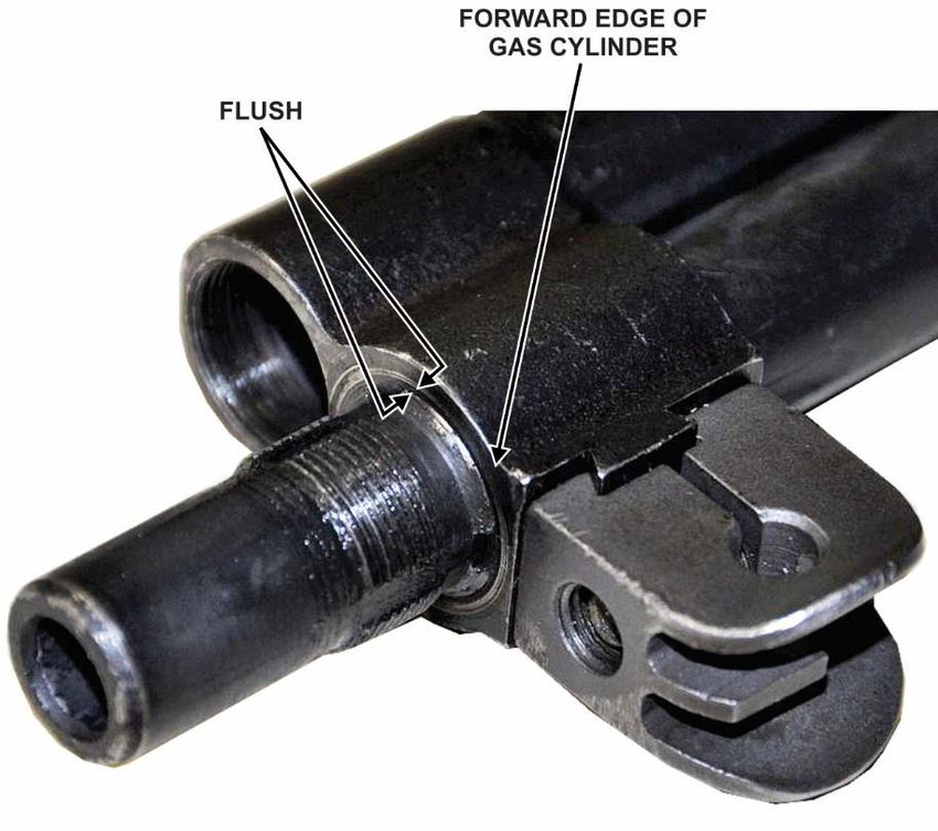
Push the safety rearward to its engaged position (inside the     WARNING: The bolt of the M1 rifle can slam shut
trigger guard) (fig 5 and 6). The M1 rifle is considered clear   unexpectedly if the shooter does not strictly follow these
when there is no ammunition in the chamber or receiver, the      instructions. If your thumb or finger is in its path, a
bolt is locked to the rear, and the safety is engaged.           painful condition/injury called “M1 Thumb” is a strong
                                                                 possibility.

                Figure 5. Safety is not engaged

                  Figure 6. Safety is engaged

M1 Garand Operation and Maintenance Guide - 9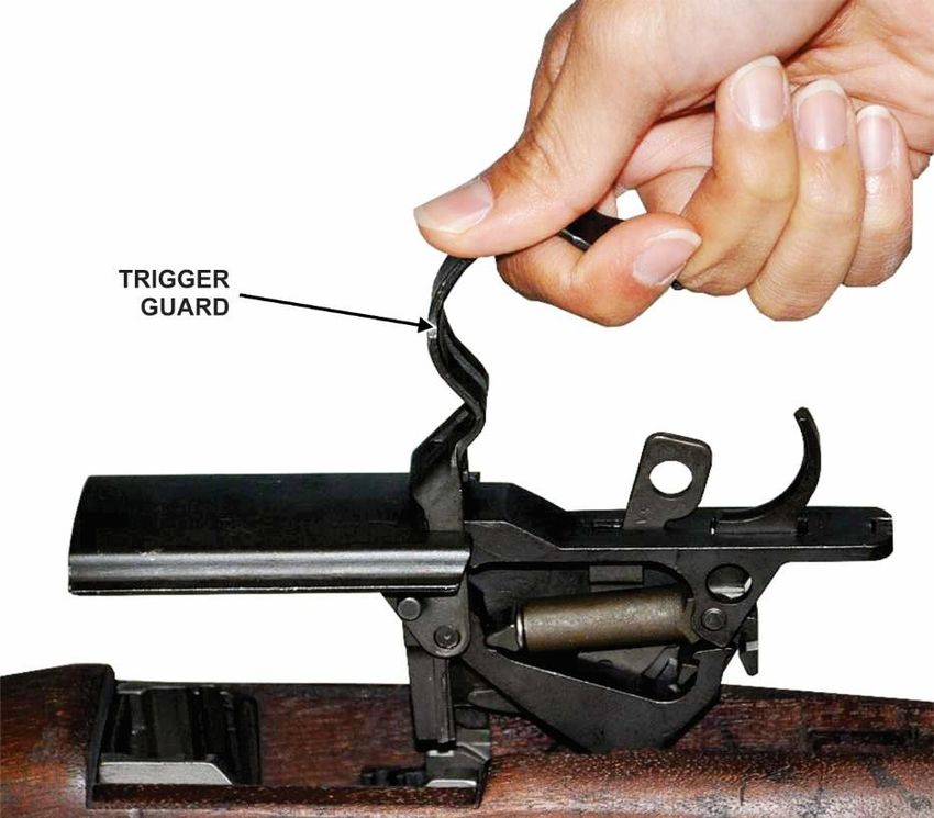
2.4 Disassembly into Three Main Groups
   1) To disassemble the rifle into three main groups –
      trigger group, barrel and receiver group, and stock
      group (fig 7) – first make sure that the weapon is clear
      (fig 8) and then allow the bolt to go forward by
      depressing the follower assembly (fig 9) and allowing
      the bolt to ride forward over the follower assembly (see
      “M1 Thumb” WARNING in previous section).

                                                                 Figure 9. Depressing the follower assembly

      Figure 7. Trigger group, barrel and receiver group,
                       and stock group

           Figure 8. Checking that weapon is clear

M1 Garand Operation and Maintenance Guide - 10
2) Rotate the elevation knob so the rear sight is at its
lowest position (fig 10). Invert the rifle and place it on
a flat surface so that the trigger assembly is facing
upward. While securing the rifle with one hand, pull
rearward and upward on the trigger guard (fig 11 and
12). Lift straight up to remove the trigger housing
assembly.
Figure 11. Trigger guard being pulled rearward and upward
Figure 10. Elevation knob and rear sight
Figure 12 Trigger guard and housing assembly being pulled out
of stock
M1 Garand Operation and Maintenance Guide - 113) Lift up on the stock to separate the stock from the barrel
and receiver group. It may be necessary to slap the
stock upward while holding the receiver (fig 13). Grasp
the stock and rotate it up and off of the barrel and
receiver group.
Figure 14. Follower rod being moved towards muzzle
Figure 13. Lifting up stock
2.5 Barrel and Receiver Group – Disassembly of the Operating
Mechanism
1) With the sights facing down, place the barrel and
receiver group on a flat surface. Hold the rear of the
receiver then grasp the follower rod. Disengage the
follower rod from the follower arm by moving it toward
the muzzle (fig 14), then slowly allow the operating rod
spring to extend in a controlled fashion (fig 15). You
may need to push down on the follower assembly
(shown in fig 14) to disengage the follower rod from
the follower arm. Remove the follower rod and Figure 15. Extending operating rod spring in controlled fashion
operating rod spring from the barrel and receiver group.
Do not separate these parts.
CAUTION: Maintain control of the follower
rod/operating rod spring until completely removed.
M1 Garand Operation and Maintenance Guide - 122) Using a 1/8 inch punch, remove the follower arm pin by 3) Grasp the bullet guide and follower arm and lift them
pushing on it from the small side of the pin (the left side out of the receiver (fig 17). Then lift the operating rod
of the rifle when it is upright and pointed downrange). catch and lift it out of the receiver (fig 18).
The large end of the pin can then be grasped and fully
removed (fig 16).
Figure 17. Bullet guide and follower arm removal
Figure 16. Removal of follower arm pin
Figure 18. Operating rod catch removal
M1 Garand Operation and Maintenance Guide - 134) Reach down into the receiver and lift the follower 5) With the receiver facing upright, pull the operating rod
assembly (fig 19). to the rear with slight upward force until it engages the
notch (fig 20) in the receiver. The rear of the handle
will be directly under the forward edge of the windage
knob (fig 21).
Figure 19. Follower assembly removal
Figure 20. Notch on receiver
Figure 21. Handle under forward edge of windage knob
M1 Garand Operation and Maintenance Guide - 146) Apply upward force and then rotate the handle 7) From the shooter’s perspective, grasp the bolt on the
clockwise to separate it from the bolt lug (fig 22). You exposed lug and slide the bolt forward while lifting it
may need to jiggle the operating rod slightly to upward and outward with a rotating motion (fig 23).
disengage it. Remove the operating rod.
CAUTION: The piston end of the operating rod is
bent intentionally so that it will not bind against the
enlarged portion of the barrel. Do not attempt to
straighten it.
Figure 23. Bolt removal by exposed lug
Figure 22. Operating rod removal
M1 Garand Operation and Maintenance Guide - 158) Using a T-grip screwdriver (preferred), or a standard 9) Loosen the gas cylinder by tapping lightly toward the
flathead screwdriver, unscrew and remove the gas muzzle on the bayonet lug with a wooden mallet or
cylinder lock screw and then unscrew the Blank Firing similar soft object (fig 26) and remove the gas cylinder
Adapter (BFA) (figs 24 and 25). If necessary, apply (fig 27).
light pressure with 7/16-inch wrench to remove the
BFA.
Figure 24. Gas cylinder lock screw removal Figure 26. Loosen gas cylinder with wooden mallet
Figure 27. Gas cylinder removal
Figure 25. BFA removal
M1 Garand Operation and Maintenance Guide - 1610) Remove the front handguard by sliding it forward over
the muzzle (fig 28).
CAUTION: Do not attempt to remove the rear
handguard.
Figure 28. Removal of front handguard
M1 Garand Operation and Maintenance Guide - 1711) The parts of the barrel and receiver group are shown below along with the stock group and trigger group (fig 29).
Figure 29. Disassembled parts of M1 Garand Rifle
M1 Garand Operation and Maintenance Guide - 182.6 Barrel and Receiver Group – Assembly of the Operating
Mechanism
1) Replace the front hand guard by sliding it over the 2) Place the gas cylinder over the barrel, making sure that
muzzle and ensuring that it is seated properly in the the splines are aligned with their grooves (fig 31).
lower band (fig 30).
Figure 31. Splines & grooves
Figure 30. Front hand guard insertion
M1 Garand Operation and Maintenance Guide - 193) Push the gas cylinder down until the forward edge is
flush with the larger diameter portion of the barrel (figs
32 and 33).
NOTE: If necessary, a wooden mallet or similar tool
may be used to tap the gas cylinder into place.
Figure 33. Gas cylinder positioned CORRECTLY
Figure 32. Gas cylinder positioned INCORRECTLY
(too far rearward)
M1 Garand Operation and Maintenance Guide - 204) Screw the BFA onto the barrel until it touches the gas 5) Attach the gas cylinder lock screw into the gas cylinder
cylinder (fig 34). with a T-grip screwdriver (preferred) or a standard
flathead screwdriver and firmly tighten using hand
WARNING: Once contact is made with the gas strength only (fig 35).
cylinder, do not tighten further.
Figure 34. BFA installation Figure 35. Gas cylinder lock screw installation
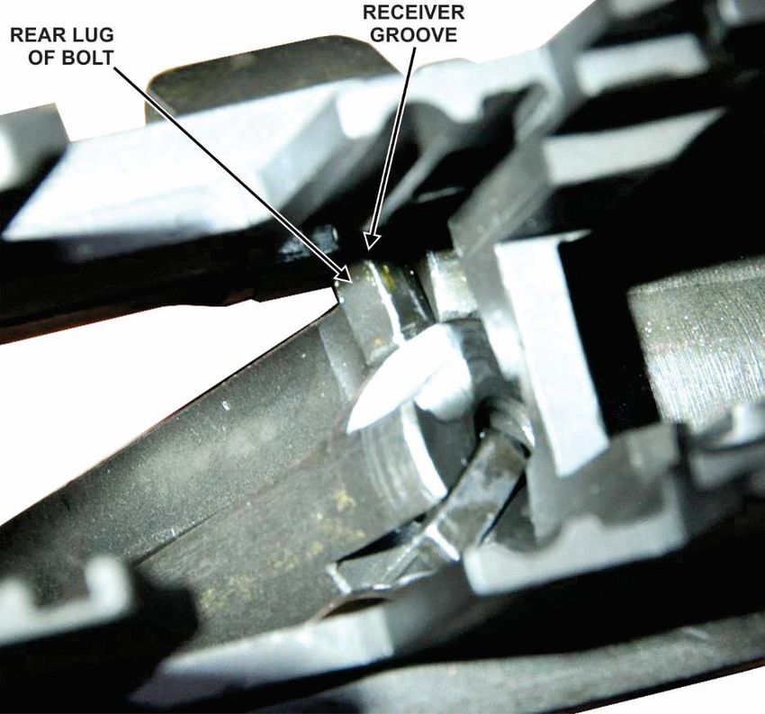
M1 Garand Operation and Maintenance Guide - 216) To replace the bolt, hold the rifle upright and guide the 7) Rotate the bolt so that the tang of the firing pin clears
rear lug of the bolt into its groove on the left side of the the notch in the bridge of the receiver (fig 37). Align
receiver (fig 36). the right locking lug on its bearing surface and slide the
bolt to the rear.
Figure 37. Tang clearing notch in bridge of receiver
Figure 36. Rear lug in groove on receiver
Note: Figures 36 and 37 show the rifle inverted. It
is not necessary to invert the rifle but the figures are
provided to aid in the bolt insertion.
M1 Garand Operation and Maintenance Guide - 228) To replace the operating rod, place the piston end into
the gas cylinder while weapon is inverted (fig 38).
9) Rotate the weapon upright and align the operating rod
so that the recess in the hump fits over the operating lug
of the bolt (figs 39 and 40). Move the operating rod
fully rearward and then forward until the bolt is closed.
Figure 39. Recess in the hump and operating lug of bolt
Figure 38. Operating rod piston end insertion
Figure 40. Operating rod replaced
M1 Garand Operation and Maintenance Guide - 2310) Invert weapon and replace the follower assembly so 11) Place the bullet guide so that its shoulders fit into their
that its guide ribs fit into their corresponding grooves corresponding notches in the receiver and the bullet
on the receiver. Make sure that the slide of the follower guide hole is aligned with the holes in the receiver (fig
is down and that the square hole is to the rear (fig 41). 42).
The slide will rest against the bolt.
Figure 41. Follower assembly insertion
Figure 42. Bullet guide insertion
M1 Garand Operation and Maintenance Guide - 2412) Slightly lift up the lower part of the bullet guide. Insert
the rear arm of the operating rod catch through the
clearance cut in the side of the bullet guide (fig 43).
Make sure that the rear arm is placed underneath the
front lug of the clip latch which projects into the
receiver (figs 44 and 45). Lower the bullet guide into
place.
Figure 44. Lug in receiver
Figure 43. Rear arm of operating rod catch
Figure 45. Rear arm of operating rod catch underneath lug of
clip latch
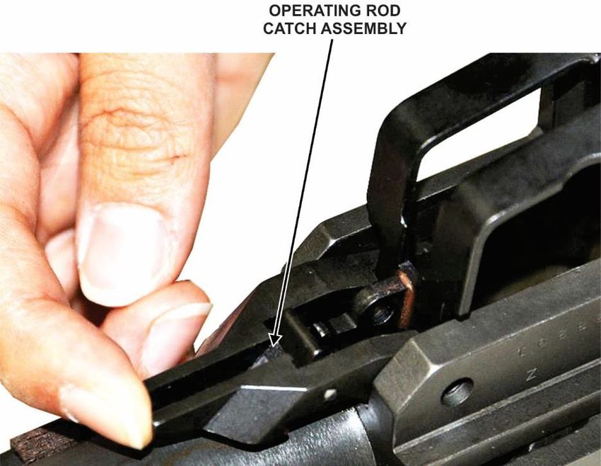
M1 Garand Operation and Maintenance Guide - 2513) Test for correct assembly by pressing down on the front
arms of the operating rod catch assembly (fig 46). It
should move and you should be able to feel the tension
of the clip latch spring.
Figure 46. Testing operating rod catch assembly
M1 Garand Operation and Maintenance Guide - 2614) Lift the follower assembly and install the follower arm
by passing its rear studs through the bullet guide and
inserting them into the guide grooves on the follower
assembly (fig 47).
15) Align the holes in the operating rod catch assembly,
follower arm, and bullet guide with those in the receiver
and push the follower arm pin through from the
operating rod side (figs 48 and 49).
Figure 48. Follower arm engaged
Figure 47. Installing follower arm
Figure 49. Insertion of follower arm pin
M1 Garand Operation and Maintenance Guide - 2716) Insert the loose end of the operating rod spring into the
operating rod (fig 50).
17) Grasp the follower rod, making sure that its hump is
down toward the barrel (fig 51). Compress the
operating rod spring and engage the forks of the
follower rod with the front studs of the follower arm
(fig 52). You may have to raise the follower assembly
to do this.
Figure 51. Orientation of follower rod
Figure 50. Orientation of follower rod
Figure 52. Insertion of operating rod spring
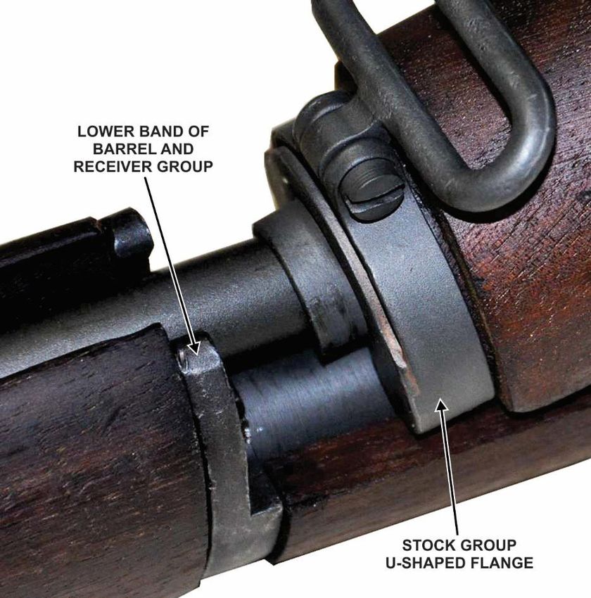
M1 Garand Operation and Maintenance Guide - 282.7 Assembly of the Three Main Groups
2) Unlatch and open the trigger guard. Keeping the trigger
1) Pick up the stock group and engage the U-shaped group level, insert it straight down into the receiver,
flange on the front of the stock into the lower band of making sure that the locking lugs on the trigger guard
the barrel and receiver group, then lower the stock enter their recesses in the receiver (fig 54).
group onto the barrel and receiver group (fig 53).
3) Close the trigger guard and latch it by pressing firmly
down until it locks. You may need to strike it with the
heel of your hand to lock it. The rifle is now fully
assembled.
Figure 54. Insertion of trigger group
Figure 53. Assembly of stock group
M1 Garand Operation and Maintenance Guide - 292.8 Blank Firing Adapter (BFA)
The threads on the BFA and where it screws into the barrel
should be examined. For lock screw assembly/tightening
procedure, see section 2.6.
2.9 Test for Correct Assembly
Each time the rifle is disassembled and assembled it should be
tested to make sure that it is put together properly. To do this,
pull the operating rod to its rearmost position. The bolt should
stay open. Close the bolt and snap the safety to its locked
position. Squeeze the trigger. The hammer should not fall.
Push the safety to its unlocked position and squeeze the trigger.
The hammer should fall. This test checks the operation of the
safety.
3.0 Operation and Functioning
3.1 Loading Rounds into a Clip
1) Start placing rounds in the lower left of the clip and
make sure that each round is against the rear wall so
that the inner rib of the clip engages the extracting
groove of each round (fig 55).
Figure 55. Loading rounds into clip
2) Each time rounds are loaded into a clip, the clip
should be checked for long rounds. If one round
extends beyond the others, it is possible that a live
round has been mixed in with blanks.
WARNING: Make sure you NEVER fire any
ammunition other than the supplied blanks in your
rifle. Firing unauthorized ammunition may result in
severe injury to yourself and others nearby, or
damage to the weapon.
M1 Garand Operation and Maintenance Guide - 303.2 Loading the Rifle
To load a single round, pull the operating rod all the way to the
rear. While holding the muzzle below the horizontal, place a
round in the chamber and seat it with your thumb. With the
knife edge of the right hand against the operating rod handle,
force the operating rod slightly to the rear. Push down on the
follower assembly with the right thumb and allow the bolt to
ride forward. Remove the thumb from the follower assembly
and release the operating rod handle, allowing the operating
rod to go all the way forward.
To load a clip, hold the rifle and pull the operating rod handle
all the way to the rear. Place the clip on top of the follower
assembly. Place your thumb on the center of the top round in
the clip (fig 56) and press the clip straight down into the
receiver until it latches. Remove your hand and allow the bolt
to travel forward freely. Note that the operating rod is not held
Figure 56. Loading of clip into rifle
to the rear after fully inserting a loaded clip. In order to
chamber the first round, it may be necessary to strike the back
of the operating rod handle with the heel of the right hand to
fully close and lock the bolt.
M1 Garand Operation and Maintenance Guide - 313.3 Unloading the Rifle (not due to a misfire) rod spring through its connection to the follower rod
and follower arm (fig 58).
To unload a round from the chamber, support the rifle, and
with the right hand, grasp the operating rod handle and pull the
operating rod slowly to the rear. At the same time, place the
left hand, palm down, over the receiver to catch the round as it
is ejected.
To unload a clip, unload the round that is in the chamber as
described above. When the operating rod reaches its rearmost
position, hold it there. Place the palm of the left hand over the
receiver and depress the clip latch (fig 57) with the left thumb,
allowing the clip to be ejected up into the hand. Do not relax
the rearward pressure on the operating rod handle until after the Figure 58. Position of parts when the bolt is in the
clip has been removed. rearmost position
2) Chambering. Chambering occurs when a round is
moved into the chamber. This takes place as the bolt
goes forward under force from the operating rod spring,
picking up the top round in the clip and driving it
forward into the chamber. Chambering is complete
when the extractor snaps into the extracting groove on
the cartridge case and the ejector is forced into the face
of the bolt (fig 59).
Figure 57. Clip latch
3.4 Functioning of the Rifle
1) Feeding. Feeding takes place when a round is moved
into the path of the bolt. This is done through the
follower assembly exerting upward force on the
remaining rounds within the clip. The follower Figure 59. Chambering
assembly exerts continuous upward force on the
remaining rounds through compression of the operating
M1 Garand Operation and Maintenance Guide - 323) Locking. Locking is complete when the bolt is fully 5) Unlocking. Unlocking occurs after the round is fired.
closed. The bolt is moved into its fully locked position Once the round is initiated, a small portion of the gas
through the camming action of the operating rod which expands through the gas port into the gas cylinder,
forces the operating lug of the bolt down. This engages forcing the operating rod to the rear (fig 62). The
the locking lugs on the bolt with their recess in the camming surface inside the recess in the hump of the
receiver (fig 60). operating rod, in combination with the guideway in the
side of the receiver, forces the operating lug of the bolt
upward, disengaging the locking lugs from their
recesses in the receiver. The bolt is thus unlocked and
ready to be moved to the rear.
Figure 60. Locking
4) Firing. Firing occurs when the firing pin strikes the
Figure 62. Action of gas moving operating rod
primer. As the trigger is pulled the trigger lugs are
disengaged from the hammer hooks and the hammer is
6) Extracting. Extracting is the pulling of the empty
released. The hammer moves forward under the force
cartridge case from the chamber. The extractor, which
of the hammer spring and strikes the tang of the firing
is engaged with the extracting groove on the cartridge
pin, driving the firing pin against the primer and firing
case, withdraws the empty case as the bolt moves to the
the round (fig 61).
rear (fig 63).
Figure 61. Firing Figure 63. Extracting an empty cartridge case
M1 Garand Operation and Maintenance Guide - 337) Ejecting. Ejecting is throwing the empty case from the 4.0 Stoppage, Immediate Action, Malfunctions, and
rifle. As the bolt moves to the rear, withdrawing the Ammunition Malfunction Reporting
case from the chamber, the round is held in place by the
chamber walls. When the mouth of the empty case A stoppage is any unintentional interruption in the cycle of
clears the chamber, it is ejected up and to the right due operation. Most stoppages occur because of dirty, worn, or
to the force exerted by the ejector (fig 64). broken parts, and/or lack of lubrication. The user should watch
for these defects and take corrective action to eliminate them
before they cause a stoppage. Some of the more common
stoppages, with their usual causes and remedies, are shown in
Table 1.
4.1 Immediate Action
Immediate action is the prompt action taken by the user to
overcome a stoppage. To perform immediate action, pull the
operating rod handle all the way to the rear with the right hand,
palm up then release it. Next, aim the rifle and try to fire it.
Figure 64. Ejecting an empty cartridge case 4.2 Malfunctions
8) Cocking. Cocking occurs when the hammer is forced A malfunction is a failure of either the weapon or ammunition
into the proper position for firing the next round. This to function as intended.
happens as the bolt moves to the rear. The rear end of
Normally, the user will instinctively apply immediate action
the bolt forces the hammer back and rides over it. The
which in most instances will overcome or correct the stoppage
hammer is caught by the sear if the trigger is still held
even when caused by a hangfire or misfire. Misfires are caused
to the rear, and is caught by the trigger lugs if trigger
by one of three factors: the user, the weapon (due to excessive
pressure has been released (fig 65).
dirt, residue, etc.), or faulty ammunition. When misfires are
caused by faulty ammunition, the lot number should be
reported to JMC. The alpha-numeric lot numbers are printed
on the ammunition can.
Figure 65. Ejecting an empty cartridge case
M1 Garand Operation and Maintenance Guide - 34Table 1. Malfunctions, Probable Causes and Actions/Remedies
Stoppage/Malfunction Probable Cause Action/Remedy
• Damaged clip • Replace clip.
Failure to load
• Improperly assembled receiver components • Disassemble and reassemble. (Section 2.4-2.7)
• Lack of lubrication of operating parts • Clean and lubricate parts. (Section 5.1-5.2)
• Defective or worn follower rod/operating rod
Failure to feed ammunition • Replace follower rod/operating rod spring. (Section 2.4-2.7)
spring
• Short recoil • See “Short recoil” stoppage/malfunction in this table.
• Lack of lubrication of operating parts • Clean and lubricate parts. (Section 5.1-5.2)
Failure to chamber
• Dirty chamber • Clean chamber. (Section 5.2)
ammunition
• Defective ammunition • Replace ammunition.
• Lack of lubrication of operating parts • Clean and lubricate parts. (Section 5.1-5.2)
• Dirty chamber • Clean chamber. (Section 5.2)
Failure to lock bolt
• Dirty locking recesses • Clean recesses. (Section 5.2)
• Weak operating rod spring • Replace follower rod/operating rod spring. (Section 2.4-2.7)
• Bolt not in battery • See “Bolt fails to close tightly” stoppage/malfunction in this table.
• Defective ammunition • Replace ammunition.
Failure to fire ammunition • Defective firing pin • Replace firing pin - contact CMP.
• Defective trigger housing group • Replace trigger housing group. (Section 2.4 and 2.7)
• Weak or broken hammer spring • Replace trigger housing group. (Section 2.4 and 2.7)
• Dirty chamber • Clean chamber. (Section 5.2)
• Lack of lubrication of operating parts • Clean and lubricate parts. (Section 5.1-5.2)
• Tighten and/or clean gas cylinder lock screw, and/or adjust or
Failure to unlock bolt • Insufficient gas
replace gas cylinder. (Section 5.1-5.2 or 2.4-2.7)
• Follower arm pin worn • Replace follower arm. (Section 2.4-2.7)
• Follower arm bent or out of tolerance • Replace follower arm. (Section 2.4-2.7)
• Dirty chamber • Clean chamber. (Section 5.2)
Failure to extract spent
• Defective ammunition • Replace ammunition.
cartridge case
• Broken extractor • Replace extractor - contact CMP.
• Broken ejector or spring • Replace ejector or spring - contact CMP.
Failure to eject cartridge case
• Short recoil • See “Short recoil” stoppage/malfunction in this table.
M1 Garand Operation and Maintenance Guide - 35Table 1. Malfunctions, Probable Causes and Actions/Remedies (continued)
Stoppage/Malfunction Probable Cause Action/Remedy
• Defective trigger housing group • Replace trigger housing group. (Section 2.4 and 2.7)
Failure to cock hammer
• Short recoil • See “Short recoil” stoppage/malfunction in this table.
• Deformed cartridge clip • Replace cartridge clip.
Cartridge clip inserts with • Broken clip ejector • Replace clip ejector - contact CMP.
difficulty • Interference between bullet guide and follower arm • Replace bullet guide or follower arm. (Section 2.4-2.7)
• Bad follower assembly • Replace follower assembly. (Section 2.4-2.7)
• Gas cylinder lock screw loose • Tighten lock screw. (Section 2.6)
• Undersized or out of round operating rod piston • Replace operating rod. (Section 2.4-2.7)
• Adjust gas cylinder (Section 2.6) or replace gas cylinder. (Section
• Improperly installed or oversized gas cylinder
2.4-2.7)
• Carbon in gas cylinder or barrel port • Clean gas cylinder or barrel port. (Section 2.4-2.7 and 5.2)
Short recoil (operating rod • Replace operating rod assembly if damaged, or relieve wood from
does not fully cycle) • Operating rod assembly binding gun stock assembly, where operating rod binds on wood. (Section
2.4-2.7)
• Leak in gas cylinder lock screw with valve • Replace gas cylinder lock screw with valve. (Section 2.4-2.7)
• Defective operating rod spring. • Replace operating rod spring. (Section 2.4-2.7)
• Bolt binding • Remove burs from bolt - contact CMP.
• Distorted or damaged receiver • Replace receiver - contact CMP.
• Extractor does not snap over rim of cartridge • Clean bolt assembly and extractor recess. (Section 5.2)
• Replace operating rod assembly if damaged, or relieve wood from
• Operating rod assembly binding gun stock assembly, where operating rod binds on wood. (Section
2.4-2.7)
Bolt fails to close tightly • Weak or broken operating rod spring • Replace follower rod/operating rod spring. (Section 2.4-2.7)
• Dirty chamber • Clean chamber. (Section 5.2)
• Frozen ejector spring and plunger • Replace ejector spring and plunger - contact CMP.
• Damaged bolt and/or receiver • Replace bolt or receiver - contact CMP.
• Insufficient headspace • Replace bolt assembly by selective fit or headspace - contact CMP.
M1 Garand Operation and Maintenance Guide - 365.1.2 Lubricants
4.3 Ammunition Malfunction Reporting
1) Lubricating gun oil or grease is used for lubricating the
In the event of an ammunition malfunction contact the U.S. rifle at normal temperatures. It should be applied to the
Army Joint Munitions Command (JMC): areas shown in Figures 66 through 68. Apply lube
sparingly to key points.
Ammunition Surveillance Division (AMSJM-QAS)
2695 Rodman Ave
Rock Island, Illinois 61299-6000
DSN 793-7295
COMM 309-782-7295
FAX 309-782-7136
usarmy.ria.jmc.mbx.amsjm-qas@mail.mil
Mailing address:
U.S. Army Joint Munitions Command, AMSJM-QAS
2695 Rodman Ave, Rock Island, IL 61299-6000
5.0 Maintenance Figure 66. Lubrication
5.1 Cleaning Materials, Lubricants, Equipment, and Parts
See CMP’s website or contact CMP (see section 1.1 of this
guide for contact information) for current information on how
and where to obtain cleaning materials, lubricants, equipment,
and parts.
5.1.1 Cleaning Solutions
1) Bore cleaner should be used as the primary cleaning
solvent for cleaning the bore.
2) Hot, soapy water or boiling water is no substitute for Figure 67. Lubrication
bore cleaner and should not be used.
3) Commercially available linseed oil
WARNING: Personnel must take protective
measures when using cleaning solutions.
M1 Garand Operation and Maintenance Guide - 37a .22 caliber brush or similar device to clean the hole and a rag
or brush to clean all available surfaces.
5.2 Cleaning the Rifle
The rifle should be thoroughly cleaned no later than the
evening of the day it is fired, particularly if the weapon is not
expected to be used within the next few days.
5.2.1 Chamber
Remove the patch holder from the cleaning rod and insert two
patches about halfway through the slot. Dip the patches in bore
cleaner, then wring or squeeze the excess fluid from the
patches. Screw the cleaning rod together (without the patch
holder) and insert it all the way into the bore. Flare the patches
out, then insert the patch holder with the wet patches into the
Figure 68. Lubrication chamber. Push the threaded end into the chamber until it
touches the cleaning rod. Hold it there with one hand and screw
5.1.3 Equipment the cleaning rod and the patch holder together. Pull the patches
to the chamber, at the same time turning the rod clockwise.
5.1.3.1 Cleaning Equipment Turn the rod several times, wiping the chamber thoroughly.
After the chamber has been thoroughly cleaned, use the
• Small arms .30 cal bore cleaning brush chamber brush in the following manner:
• Lubricant
1) Screw a section of the cleaning rod into a threaded hole
• Chamber cleaning brush of the driver ratchet.
• Cleaning rod (commercially available) 2) Place the brush into chamber of the barrel.
• Shop rags or lint-free towels 3) Allow the rifle bolt to slowly close against the end of
the driver ratchet.
5.1.3.2 Blank Firing Adapter
4) Using the rod section as a handle, rotate the driver both
The optimal vent hole size for a BFA is 0.172 inches. Blank clockwise and counterclockwise to loosen and clean
firing adapters can be purchased pre-drilled to this size from residue from the chamber.
commercial retailers. This BFA will typically result in the best 5) Insert a dry patch in the patch holder and insert into the
performance of a M1 Rifle in good operating condition. The chamber to remove any excess bore cleaner.
BFA should be cleaned along with the rest of the weapon. Use
M1 Garand Operation and Maintenance Guide - 385.2.2 Bore 5.2.3 Gas Cylinder Lock Screw Assembly
To clean the bore, saturate the bore brush with cleaning Remove carbon deposits by using bore cleaner, and then wipe
compound solvent (rifle bore cleaner) and: the part and oil it lightly (do not use abrasives). Check the
valve to make sure it is not held open by particles of dirt or
1) Insert the bore brush into the chamber. Insert the sand.
cleaning rod into the bore and screw the brush onto the
rod. 5.2.4 Piston Operating Rod
2) Pull the brush through the bore. Remove the brush and Remove carbon from the piston with bore cleaner. Take care
repeat the procedure as often as required to clean the not to damage the piston. Oil it lightly after cleaning (do not
bore. use abrasives).
3) Use one cleaning patch dampened with bore cleaner in 5.2.5 Gas Cylinder
the following manner:
a) Place the patch in the patch holder and insert it into Clean the gas cylinder with bore cleaner and patches.
the chamber. Once complete, the bore cleaner must be removed with dry,
clean patches or a clean cloth.
b) Insert the cleaning rod (without the patch holder)
into the bore and screw it onto the patch holder. 5.2.6 Face of the Bolt
c) Pull the cleaning rod through the bore. Repeat this Clean the face of the bolt with a patch and bore cleaner, paying
procedure using as many patches as required until particular attention to its inside edges. Remove the bore
the patches come through the bore clean. cleaner with dry patches and oil the part lightly.
4) Remove the excess bore cleaner in the following
manner: 5.2.7 Rifle Stock
a) Place a dry patch in the patch holder and insert it Use a dry, lint free towel to remove all dirt, sand, or foreign
into the chamber. material from the surface of the stock. Apply a commercially
b) Insert the cleaning rod (without the patch holder) available linseed oil to the surface of the stock (wood only) and
into the bore and screw it onto the patch holder. allow to stand for two hours to be absorbed. After two hours,
wipe off any excess oil and polish with a clean dry cloth. Be
c) Pull the cleaning rod through the bore. Repeat this careful not to allow linseed oil to get into crevices of
procedure using as many patches as required until mechanism as it will form a residue as it dries.
the patches come through the bore clean.
NOTE: If there is a question concerning the serviceability of an
M1 Garand stock, CMP should be contacted for disposition
recommendations. They can be contacted at: Civilian
M1 Garand Operation and Maintenance Guide - 39Marksmanship Program, 1401 Commerce Blvd., Anniston, AL
36207 Tel. 256-835-8455/Fax. 256-835-3527,
www.thecmp.org.
5.2.8 All Other Parts
Use a dry cloth to remove all dirt or sand from other parts and
exterior surfaces. Apply a light coat of oil to the metal parts.
5.3 Routine Maintenance
5.3.1 Daily Inspection
When in use, the rifle should be inspected daily for evidence of
burred, worn, or cracked parts, rust and general appearance. A Figure 69: M1 Garand Rifle
light coat of oil (any protective lubricant) should be maintained BFA Inspection
on all metal parts.
NOTE
The BFA should be cleaned properly prior to conducting
5.4 Blank Firing Adapter/Barrel Inspection Criteria inspection.
5.4.1 BFA Inspection
3. Once removed, check the BFA for any signs of structural
Disassembly damage, which include but are not limited to the following:
1. While holding the M1 Garand Rifle, use a flat tip screw a. Any cracks along the orifice, base, or surface of the BFA
driver to unscrew and remove the Gas Cylinder Lock b. Any dents or bends on the BFA
Screw from the Gas Cylinder (Figure 69). c. Any deep scratches on the BFA
d. Any punctures on the BFA
2. Then unscrew and remove the Blank Firing Adapter e. Thread wear
from the M1 Garand Barrel. Please note, if the BFA f. Corrosion on the threads
cannot be removed by hand, use a 7/16-inch wrench and
apply light pressure to remove the BFA. If any of the damage listed above in a. – f. or any damage that is
observed but not listed is found, the BFA should not be used and
should be replaced with a serviceable BFA.
M1 Garand Operation and Maintenance Guide - 40If corrosion is found on the threads, the threads should
be cleaned with a 9/16” steel bristle tube brush, a clean
rag and penetrating oil. Once the corrosion is removed
from the threads, the threads should be inspected again
for signs of damage from the corrosion, which include
thread wear and pitting. If any damage is found, the Figure 71: Pin B
BFA should not be used and should be replaced with a
serviceable BFA. Pin C: Class Z 0.170 plus pin (0.170” -
0.0000”/+0.0001”)
4. If the BFA does not show any signs of structural
damage, the orifice in the BFA should be inspected.
The orifice of the BFA should be 0.172 -0.002/+0.005
inches in diameter. An orifice of 0.172” is the optimal
diameter for firing the M1909 blank cartridge in the
M1 Garand for ceremonial purposes.
a. To complete this inspection, the following pin Figure 72: Pin C
gauges will be needed:
CAUTION
When conducting an inspection with a pin gauge,
Pin A: Class Z 0.177 plus pin (0.177” - the inspection should be conducted at surface level
0.0000”/+0.0001”) over a clean flat soft surface (such as a table covered
with a rubber mat) so that if the gauge is dropped, it
is dropped from a minimal height and that it lands
on a surface that will prevent damage to the gauge.
NOTE
Pin Gauges should be stored in a clean dry place to
Figure 70: Pin A prevent corrosion. If the gauge shows signs of
corrosion or damage, the gauge should not be used
Pin B: Class Z 0.177 minus pin (0.177” - for the inspection and should be replaced.
0.0001”/+0.0000”)
M1 Garand Operation and Maintenance Guide - 41b. When conducting a pin gauge inspection, the any resistance and without exerting pressure on
pin should be held along its side with minimal the pin. Never use pressure to “force” the pin
pressure between the thumb and index finger into the hole.
(Figure 73). The gauge should never be held in
a manner that puts pressure on the end of the pin d. The hole should be inspected with pins A-C in
(Figure 74). order and whether the pin could be inserted into
the hole should be recorded. The results from
the inspection should be compared with the
following chart to determine if the orifice is
serviceable.
Orifice
Pin A Pin B Pin C
Results
Inserted
- - Not
Serviceable
Figure 73: Proper Hold
Cannot Be
Inserted
Inserted
- Serviceable
Cannot Be Cannot Be
Inserted Serviceable
Inserted Inserted
Cannot Be Cannot Be Cannot Be Not
Inserted Inserted Inserted Serviceable
e. If the BFA orifice is determined to be not
serviceable, the BFA should not be used and
should be replaced with a serviceable BFA.
5. If the BFA orifice is serviceable, the thread diameter of
the BFA should be inspected. The thread diameter of
Figure 74: Improper Hold the BFA should be 0.5287 –0.0000/+0.0046 inches.
c. When conducting the inspection, the pin should
fit in the hole by “falling” into the hole without
M1 Garand Operation and Maintenance Guide - 42a. For this inspection a standard dial caliper
(Figure 75) or electronic caliper (Figure 76)
with an accuracy of ±0.001” will be needed.
Figure 75: Dial Caliper
Figure 77: Internal Jaws of a Caliper
b. Close the caliper completely and ensure that the
caliper reads 0.000” (Figure 78). If the caliper
does not read 0.000”, consult the caliper manual
for procedures to zero the caliper and zero the
caliper before performing the inspection.
Figure 76: Electronic Caliper
Figure 78: Reading a Dial Caliper
M1 Garand Operation and Maintenance Guide - 43c. Insert the inside measuring contacts or internal
measuring jaws of the caliper (Figure 77) into
the threaded opening of the BFA. Slowly open
the caliper by using the adjusting roller until the
contacts touch the threads of the BFA. The
contacts should be centered in the diameter of
the BFA (Figure 79).
Figure 80: Reading Dial Caliper e.g. 1.932 inch
e. Close the caliper and remove the contacts from
the BFA opening.
f. Rotate the BFA 90° and take another
measurement 90° from the first measurement
using the same method as the first (Figure 79).
g. If the measurements taken are not between
0.5287” – 0.5333”, the BFA should not be used
Figure 79: Diagram of Measurements and should be replaced with a serviceable BFA.
d. Read the caliper measurement (Figure 80) and
record this measurement. 5.4.2 Barrel Thread Inspection
NOTE
The Barrel should be cleaned properly prior to
conducting inspection.
6. In addition to inspecting the threads on the BFA, the
threads on the rifle barrel need to be inspected.
a. Visually inspect the threads for wear and
corrosion. If wear is found, the barrel should
M1 Garand Operation and Maintenance Guide - 44You can also read