AUTOCAD CIVIL 3D SURVEY ESSENTIALS - JOHN COOKE CIVILTRAINING, LLC A DIVISION OF WETLAND STUDIES AND SOLUTIONS, INC.
←
→
Page content transcription
If your browser does not render page correctly, please read the page content below
AutoCAD Civil 3D
Survey Essentials

John Cooke
CivilTraining, LLC
a division of Wetland Studies and Solutions, Inc.
Training presentations and materials by CivilTraining, LLC are

            copyrighted and licensed for each exclusive engagement.

Any recording, reuse or redistribution without prior written consent is prohibited.
Working with Points in AutoCAD® Civil 3D®

Working with Points
Any discussion of points in Civil 3D must begin with a working definition of points - within our context
points are simply stored coordinates.

Points in Civil 3D are stored coordinates to which point numbers are assigned. The point numbers are an
absolute index on the stored points; a point number cannot be duplicated in a Civil 3D drawing. In
addition to stored northing, easting and point number, a point in Civil 3D may also have an elevation and
a description. As Civil 3D stores these data there may also be additional information stored, including
latitude and longitude, grid coordinates, short and long descriptions and more, but the basic stored
information consists of point number, northing, easting, optional elevation and optional description.

The means by which points are "stored" is unique in Civil 3D, and quite different from other civil
products. While programs like Land Desktop or Carlson store their points in external data files, Civil 3D
stores its points within the drawing, displayed and listed in the Prospector. There are exceptions to this
statement, and under some circumstances points in Civil 3D do behave exactly like those from Land
Desktop, displayed in a drawing from an external database, but certain conditions in Civil 3D must be
met to enable this - so the basic statement made is true: Civil 3D "stores" its points within the drawing.

Points can serve many roles in the Civil 3D drawing, some obvious, many overlooked. Most operators
are familiar with points as the primary interface for bringing field information in from a survey, and this
certainly accounts for the majority of point data seen in Civil 3D. Points are an extremely powerful tool
for grading however, and there are excellent point-based grading tools that most operators overlook.
The data management applications for points are also powerful yet untapped, and the crossover line
into what would traditionally be viewed as GIS can become very blurry indeed.

Points, Objects and Styles

Points in Civil 3D represent an evolution in the complexity of Civil 3D data management as compared
with the surfaces discussed in previous chapters. Points in Civil 3D continue to be objects, with display
and editing behavior unlike those of basic AutoCAD objects. The display of points in Civil 3D involves the
interaction of two styles, while surfaces required only one: a Point Object Style which controls the
display of the point "symbol" itself, and a Point Label Style which configures the fields of stored data
labeled on each visible point in the drawing. Point display management is actually contingent on other
optional tools, including the use of Description Keys and default point Feature Settings, so the topic
ratchets up the complexity somewhat over the refreshingly simply surfaces already examined…

03/04/2014      2.05 © Copyright (2014) Wetland Studies and Solutions, Inc. Do not reproduce without permission.   1

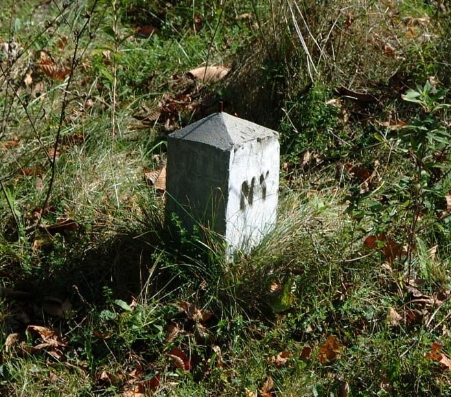
Exploring Points in Civil 3D The best way to begin an examination of points in Civil 3D will be to create a point and look at its characteristics, rather than talking about points in the abstract. The drawing being used is the Existing Base drawing in which the surface was produced in the preceding chapter. The surface is set to a _No Display style, and the contours seen are actually the original aerial contours from which the surface was produced. A new layer has been set current, V- MISC-P, following the layers standards in use in the drawing (the V prefix indicating Survey information, and the P suffix indicating that the layer contains points as opposed to lines or text on L or T layers respectively) . There is a concrete monument that forms the primary control point for all of the survey work in the Chestnut Ridge Estates project. The control is a NY DOT monument with known northing, easting and elevation. The monument falls at the intersection of the east-west county road (Weybridge Road) and the north-south town road (Chestnut Ridge Road), in an area as shown in Figure 1.01. A photo of the monument itself is seen in Figure 1.02. Figure 1.01 - Intersection Where Monument is Located Figure 1.02 - Concrete Monument Tools in Map can be used to link the photo to the point created in Civil 3D, so that clicking on the point will display the photo. The coordinate data for the monument can be found in the \Received\From Surveyor folder in the project, in a text file named Concrete Monument Weybridge at Chestnut Ridge. The full information on the monument is as follows: Northing = 1044008.2320 Easting = 668237.1924 Elevation = 229.8 Latitude: N 41° 41' 51.28" Longitude: W 73° 51' 18.29" 03/04/2014 2.05 © Copyright (2014) Wetland Studies and Solutions, Inc. Do not reproduce without permission. 2

To set the point in the Existing Base drawing a command will be used from the Home tab of the
Civil 3D ribbon. On the Create Ground Data panel, opening the Points dropdown opens a
menu, from which Create Points - Miscellaneous Northing/Easting is selected.
Figure 1.03 - Create Points by Northing/Easting
The command prompts:
>>>>Enter northing : 1044008.232 type northing value, press Enter.
>>>>Enter easting : 668237.1924 type easting value, press Enter.
Enter a point description : MON type desired point description, press Enter.
Specify a point elevation : 229.8 type elevation value, press Enter.
The point is placed in the drawing, the coordinate echoed back to the screen in the current decimal
precision of the drawing, and the command prompts for the next coordinate value:
N: 1044008.2320' E: 668237.1924'
Please specify a location for the new point:
>>>>Enter northing : Press Escape at this prompt to end the Northing/Easting
mode.
Please specify a location for the new point: Press Enter to end the command.
A dialog is left on the screen as the command ends, as seen in Figure 1.04 on the next page. Close
the dialog box for now with the in its upper right corner.
We'll talk more about that dialog bar in a little while. There's actually quite a bit we're not
discussing yet, including the description typed and why we recommended terminating a command with
Escape - usually a no-no. Trust us - we just need to get the horse before the cart here.
03/04/2014 2.05 © Copyright (2014) Wetland Studies and Solutions, Inc. Do not reproduce without permission. 3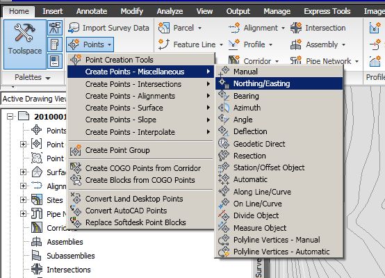
Figure 1.04 - Create Points Interface and Monument Point in Drawing

The point has appeared in the drawing as seen in
Figure 1.04. Looking in the Prospector, and
clicking on the Points collection, point
information is displayed in the bottom pane of the
Prospector. The information displayed in the
Prospector is effectively the point database; at the
moment the point can be edited by changing the
information displayed there. If the point is erased
from the drawing with an AutoCAD erase command
it disappears from the Prospector as well.                                 Figure 1.05 - Point display in Prospector

Focusing on the object in the drawing, the Properties Palette reveals more information about what is
present and how it is being displayed. Properties lists the object as a Cogo Point; its Style is listed
as SV_MON, and its Point Label Style as EX L80 Description. Together, these three pieces of
information explain much of what is in the drawing.

                                  Figure 1.06 - Point Display and Information in Properties

03/04/2014      2.05 © Copyright (2014) Wetland Studies and Solutions, Inc. Do not reproduce without permission.       4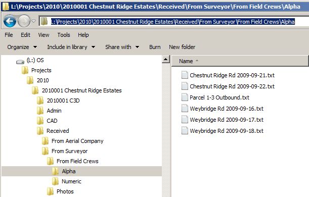
The Cogo Point is a custom Civil 3D object, not unlike the surface. This is a unique entity created by Civil 3D to represent civil engineering and surveying data: the point, as generically defined above. To get more specific, the point in the drawing at the moment is a Civil 3D Point, also referred to as a Drawing Point. This is contrasted with something we'll show later: a Survey Point. A Civil 3D Point or Drawing Point exists only in the current drawing. It may or may not be visible in the drawing based on settings we'll explore, but a Civil 3D Point or Drawing Point exists within the Prospector of the drawing in which it is placed - the Prospector serves as the "database" once again. Civil 3D Points or Drawing Points exist only in a single drawing; if the same point is needed in another drawing it must be created in that drawing, as there is no way to expose Civil 3D Points or Drawing Points from drawing to drawing. Throughout this manual we'll use the terms Civil 3D Points or Drawing Points interchangeably from here. The Survey Point is something entirely different. A Survey Point is actually a record in a point database external to the Civil 3D drawing, very similar to the point database in Land Desktop or Carlson. Survey Points may be inserted into a drawing, and they are represented in that drawing by Civil 3D Points, albeit with special locking and editing characteristics as we'll see. The same Survey Points can be inserted in any number of drawings within the Civil 3D project, much like in Land Desktop. We'll examine Survey Points to some extent in this chapter, and in much more detail in chapters that follow. The use of the Survey Point Database as the central location for all point data is very desirable, even when not using traditional "Survey" functionality. Using the Survey Point Database adds tremendous security to point data, and simplifies the sharing of points between drawings. Returning to the information displayed in the Properties Palette, the Cogo Point was displayed using a Point Object Style, SV_MON, and a Point Label Style, EX L80 Description. The Point Object Style selection configures the display of the point as the monument symbol, and the Point Label Style selection configures the display of the labeled information as an existing label (slanted text), Leroy 80 size (0.08" plotted height) and Description field only. These settings were totally dependent on the operator (or more likely the CAD Manager), and were settings created in the drawing and passed on through Point Feature settings. All of these will be examined here in due course. Looking a little further in the drawing, the point created sits on the layer V-BOUNDARY-P, in spite of the current layer being set to V-MISC-P. The layer on which the point is inserted is under the control of another tool in Civil 3D, Description Keys. Description Keys also stepped in to assign the Point Object Style and Point Label Style if needed, and they are part of a hierarchy of control of point display that we'll examine, involving Layers, Point Object Styles, Point Label Styles and Point Groups. This will all seem very complicated at first glance, but the point display management in Civil 3D is incredibly powerful once one gets used to its nuances; it is actually much more flexible than point display control in Land Desktop or even Carlson. The point display strategy which is presented here is admittedly only one of several that could be used in Civil 3D. Relying primarily on control by Point Groups, this strategy has the advantage of very fluid control over point display. While one could elect to use a point display scenario based more traditionally on layers, we feel that this strategy offers significant benefits in drawing size and performance, as well as operational advantages. 03/04/2014 2.05 © Copyright (2014) Wetland Studies and Solutions, Inc. Do not reproduce without permission. 5
Point Feature Settings
As we've already discussed, each Feature in Civil 3D has its own settings which control the display of its
objects, as well as other settings that fine-tune the way the program operates. There are a number of
Point Feature Settings which can be important. While some of these should at least be checked before
working with points, many of the settings can be adjusted on the fly, often in the Create Points dialog
which we'll examine.

Point Feature Settings are again controlled from the Toolspace's Settings tab, at the parent
level of the collection (Point), and the Commands level for the operation to be used (CreatePoints).

Feature Settings

To begin examining Point Feature Settings, Right-Click on Point on the Settings tab, and pick
Edit Feature Settings.

Once again, our focus here will be to discuss only the settings that are really important for each
operation we'll perform. While there are three levels of Point Feature Settings in the Edit Feature
Settings - Point dialog as evidenced by the     glyphs, only one is really important at this time: Default
Styles. Expanding the Default Styles level in the dialog, notice the selections made in this
drawing:                                                                                       .

                                              Figure 1.07 - Point Default Styles

The selection of default a Point Object Style and Point Label Style of  may seem strange, and
could lead one to believe that the point would be neither visible nor labeled in the drawing based on
this selection. In fact, however, this setting means that the assigned Point Object Style and Point Label
Style are not fixed by this setting, but instead are variable, and under the control of another element
downstream in the process - Point Groups. This setting, strange though it seems, is a critical component
of the point display strategy supported by Civil 3D, which passes primary control of point display to Point
Groups.

Leaving the Point Object Style and Point Label Style setting as , press OK to exit the Edit Feature
Settings - Point dialog.

03/04/2014      2.05 © Copyright (2014) Wetland Studies and Solutions, Inc. Do not reproduce without permission.   6
Command Settings
There are several individual levels of Command Settings that influence point creation. Many of these
directly resemble the point settings in Land desktop, and most can be adjusted on the fly later. To
access the settings, Right-click on CreatePoints under Commands below the Point
collection on the Settings tab, and pick Edit Command Settings. The new settings levels
should be announced by the new glyph at this level, but one new level has inherited the glyph
from the parent Feature Settings level.
Can you say "Overly complicated user interface?"
Default Layer Settings
The first of three levels of important Point Command Settings are found by expanding the Default
Layer level in the Edit Command Settings - CreatePoints dialog.
Figure 1.08 - Default Layer Command Settings
The Default Layer for the placement of a point is set to ; clearly the monument
point placed earlier did not go to the current layer, so something else was in play.
03/04/2014 2.05 © Copyright (2014) Wetland Studies and Solutions, Inc. Do not reproduce without permission. 7Points Creation Settings
The second level of important Point Command Settings is found by expanding the Points Creation
level in the Edit Command Settings - CreatePoints dialog.
Figure 1.09 - Points Creation Command Settings
Several of these settings control the prompting for default values on point placement: Prompt for
Elevations, Prompt for Descriptions and Prompt for Point Names; the selection
for each can be Manual, Automatic or None.
As in Land Desktop, Point Names are alphanumeric point numbers, actually aliases for integer
point numbers.
The Default Elevation, Default Description and Default Point Name entries
supply the command line default when each corresponding attribute is set to Manual, or the attribute
placed when Automatic is enabled.
The Disable Description Keys setting seems somewhat strange. When this setting is False,
the use of Description Keys is On. This seems like a double negative, but the way the interface works.
Description Keys are being used in this example, so the value is set to false.
The Match on Description Parameter ($1, $2, etc.) setting allows the use of
replaceable parameters in point descriptions, separated by spaces. More information of the use of
multiple attributes on points follows in later chapters on survey Field to Finish techniques.
03/04/2014 2.05 © Copyright (2014) Wetland Studies and Solutions, Inc. Do not reproduce without permission. 8Point Identity Settings
The other level in the Edit Command Settings - CreatePoints dialog which is important is Point Identity.
Click to expand the Point Identity level.
Figure 1.10 - Point Identity Command Settings
The Next Point Number setting establishes the current point number; Use Sequential
Numbering can then be turned off or on as desired.
Most of the remaining settings affect the processing of point numbers when points are imported from
external files. The difference between Point Number Offset and Sequence Point
Numbers From can be confusing; Point Number Offset can be used to "bump" point numbers by
adding an offset value such as 10000 to numbers already on points, whereas Sequence Point Numbers
From always renumbers imported points.
Most of the Point Identity settings will need to be adjusted on the fly, so we'll return to these settings
later when cross section points for the two roads in the example project need to be imported.
Press OK to close the Edit Command Settings - CreatePoints dialog.
03/04/2014 2.05 © Copyright (2014) Wetland Studies and Solutions, Inc. Do not reproduce without permission. 9Point Description Keys Description Keys are an optional tool in managing point display in Civil 3D, but really should be considered an essential tool. Description Keys automate the control of Point Object Styles and Point Label Styles as points are placed, by matching point descriptions entered and assigning styles accordingly. Description Keys also handle the layer management of points, which really is of less importance than it was in Land Desktop due to the use of Point Groups. Point Description Keys are also found on the Toolspaces's Settings tab. Expand the Description Key Sets level under the Point collection, and two Description Key sets are found, inherited from the CivilTraining dwt template file. The CivilTraining Alpha description key set is intended for use with alpha point descriptions, typical of most field work. The CivilTraining Alpha description key set worked in the example thus far, found, and matched on the typed description MON as will be seen momentarily. The CivilTraining Numeric description key set is intended for use with numeric point descriptions, less common in field work. The CivilTraining Numeric description key in this example would have expected a description of 85 for the monument, and would have found and matched on that typed description. Either set could be used, and one set deleted from the prototype if desired. Multiple Description Key sets can be used in a drawing, but any in the drawing are active; they cannot be selectively turned on and off. To examine the Description Keys in use in this example Figure 1.11 Description Key Sets Right-click on the CivilTraining Alpha description key set and pick Edit Keys from the menu. 03/04/2014 2.05 © Copyright (2014) Wetland Studies and Solutions, Inc. Do not reproduce without permission. 10
The Description Key set opens in the DescKey Editor, which is a tab in the Panorama.

                          Figure 1.12 - CivilTraining Alpha Description Key Set in DescKey Editor

The Code column in each Description Key specifies the point description entry that will be matched;
the use of the " * " wildcard permits matching on a string that begins with the desired characters but
continues with other values.

The Style column assigns a particular Point Object Style to be used when a match is found. There are
a number of different styles in the drawing, and more information on these styles follows later in this
chapter.

The Point Label Style column assigns a particular label style when a match is found; different
label composition can be used for different points as seen in the dialog. Again, more information on the
Point Label Styles will follow shortly.

The Format column handles the processing of point descriptions entered, and configures the amount
and content of the data that will show up in a point label. Point descriptions in Civil 3D can consist of up
to ten (10) attributes, separated by spaces. The first attribute is the one on which the description key
itself is matched; the program assigns this attribute the number $Ø. Each succeeding attribute,
separated again by a space, is assigned a number: $1, $2, $3, etc. The use of $1 $2 in the description
key formats shown above are placeholders. If a point has a value in the $1 or $2 attribute that attribute
label will show up in the point label. The point set earlier had a description typed of MON; had it been
typed as MON NY DOT it would have been labeled as such: NY would have been in the $1 variable,
DOT in the $2 variable, and the MON* description key shown in the dialog box is set to label the point
as MON $1 $2. Had the point been entered as MON NY DOT CONC it still would have labeled as MON

03/04/2014      2.05 © Copyright (2014) Wetland Studies and Solutions, Inc. Do not reproduce without permission.   11
NY DOT, because the format column does not include $3. The full MON NY DOT CONC description
would still display in the Point List in the Prospector, however.
The use of the value $* in the Format column means that the full description as entered will be used
in the point label, without any restrictions.
The Layer column assigns the layer on which the point itself will reside; this setting overrides the
Default Layer point command setting when a match is found.
The remaining columns affect the scaling and rotation of Point Objects; much more detail on these
settings can be found in the survey Field to Finish chapters later in this manual.
The DescKey Editor can be closed by clicking on the button in the Panorama.
For sake of comparison, Right-click on the CivilTraining Numeric Description Key set under the
Description Key Sets collection on the Settings tab, and pick Edit Keys from the menu.
Figure 1.13 - CivilTraining Numeric Description Key Set in DescKey Editor
The format of the CivilTraining Numeric Description Key set is slightly different, but the operation is the
same. No entries in the Format column are set to $* in this Description Key set; instead, each
numeric description is replaced with a different alpha value. $1 $2 continues to be used in some
descriptions, and a mix of numeric and alpha entry is actually employed in the field with this particular
set.
Again, close the DescKey Editor by clicking on the button in the Panorama.
03/04/2014 2.05 © Copyright (2014) Wetland Studies and Solutions, Inc. Do not reproduce without permission. 12Description Key Set Search Order
When more than one Description Key set is present in the drawing as is the case here, the order in
which they are to be evaluated for matches is specified through a Search Order function.
To set the Search Order, Right-click on Description Key Sets on the Settings tab, and
click Properties from the menu.
Figure 1.15 - Search Order Dialog
Figure 1.14 - Description Key Set Properties
The order in which matches are processed from the multiple Description Key Sets is established by their
relative position in the Description Key Sets Search Order dialog. The program will look for matches in
the first Description Key Set found in the dialog. If a match is not found, the program moves down
through the list through any additional files. The search order is set in the dialog box by
highlighting a Description Key Set and moving it up or down in the list with the or buttons.
Curiously, there is no function to turn off the processing of a Description Key Set. The only way to
accomplish this is to delete the set from the drawing. If the same Description Key Set is in another
drawing this is safe. A Description Key Set can be dragged and dropped from one drawing to another. A
set can be dragged into another drawing temporarily, and then deleted in the current drawing. When
needed back in the current drawing it can be dragged back, accomplishing the same function as turning it
off.
03/04/2014 2.05 © Copyright (2014) Wetland Studies and Solutions, Inc. Do not reproduce without permission. 13Point Groups Point Groups are a critical component of Civil 3D, and an essential tool in point display management. Point Groups reside on the Prospector; clicking back to the Prospector tab and expanding the Point groups level reveals a number of Point groups already in this drawing, and a potential surprise. The glyph in front of the _No Display point group indicates that the group may not be up to date, and needs to be updated. This situation results whenever a point group is in place in the drawing before points are added to the drawing, and indicates that the new points may not be correctly reflected in the point groups without an update. To update the point groups Right-click on Point Groups in the Prospector, and click Update from the menu. Figure 1.15 - Update Warning Glyph Figure 1.16 - Point Group Update on Menu Figure 1.17 - Point groups After Update Most of the point groups shown in the example are in the template drawing at the discretion of the operator; one shown is always present, and one should always be present. The _All Points point group is always present in Civil 3D, and, by default, every point placed in a Civil 3D drawing is a member of this group. Although Civil 3D establishes no clear direction as to how this group should be used, it should serve one purpose: the _All Points point group should be used to provide the default appearance of points with respect to their Point Object Style and Point Label Style, either by specifying the two styles explicitly or by enabling the display as configured by Description Keys. The _No Display point group is not always present in Civil 3D, but it should be. Like the _All Points group, every point placed in a Civil 3D drawing is a member of this group (the mechanics of this follow). This group likewise has one purpose: the _No Display point group should be used to suppress the appearance of points by overriding their Point Object Style and Point Label Style with a selection of , regardless of whether the point acquired its Point Object Style and Point Label Style from another group or from Description Keys. If this these two groups are created and used as described, and if all other display management of points is likewise handled by point groups, the display management of points in Civil 3D is very easy and very efficient. 03/04/2014 2.05 © Copyright (2014) Wetland Studies and Solutions, Inc. Do not reproduce without permission. 14
Using Point Groups to Manage Point Display
With display management configured through point groups, controlling point display in Civil 3D becomes
easy and reliable: point display is controlled by a Display Order function built into Point Group
Properties.
Using the _No Display Group
The purpose of the _No Display point group is to suppress the display of points within it.
Right-click on Point Groups on the Prospector, and click Properties from the menu.
In the Point Groups dialog, highlight the _No Display group and shift it to the top of the list, above all
other groups, using the button. The list in the Point Groups dialog establishes a display order for
the group contents. If a point is a member of one or more point groups it will be displayed using the
properties of the topmost group of which it is a member in the dialog. Since all points are members of
the _No Display group, and this group suppresses the Point Object Style and Point Label Style of all of
its member points with a selection of , points will disappear or vanish from the drawing when
this group is at the top of the list.
Figure 1.18 - Point Group Properties on Menu Figure 1.19 - Point Groups Dialog and Display Order
Pressing OK and checking the drawing,
the monument point has disappeared, as
seen in Figure 1.20.
If the point does not immediately
disappear, regen the drawing. Trust us, it
was there….
Figure 1.20 - Drawing with _No Display Group at Top of Display Order
03/04/2014 2.05 © Copyright (2014) Wetland Studies and Solutions, Inc. Do not reproduce without permission. 15Mechanics of the _No Display Group
Some explanation of exactly how the _No Display group
works will be helpful, and will expand our exploration of
point management.
In the Prospector, right-click on the _No
Display group and click Properties from the menu.
Figure 1.21 - Point Group Properties on Menu
Point Group Properties is a tabbed dialog, and three of the tabs are important here. Begin by clicking to
the Information tab.
On the Information tab the Point Style and Point Label style are both set to . This means that a
point displayed through the configuration established here would not be visible. This setting alone
would be enough to control the display of a point if it did not match a Description Key or if no
Description Key Set were in use. There's a display hierarchy for points, and Description Keys trump
point groups.
Figure 1.22 - Point Group Properties - Information Tab
03/04/2014 2.05 © Copyright (2014) Wetland Studies and Solutions, Inc. Do not reproduce without permission. 16Click next to the second important tab in Point Group Properties, the Include tab.
The Include tab specifies what points will be members of the point group. In this case the option used is
Include all points. It should be mentioned that using this option is dangerous in most other
cases, as every point placed in the drawing will be included in this group. Usually group membership is
better specified using the other options in the dialog, but this is one of the rare cases where every point
should be part of this group.
Do not use Include all points when creating point groups for building surfaces, as all
points ever added to the drawing will be added to the surface.
Figure 1.23 - Point Group Properties - Include Tab
03/04/2014 2.05 © Copyright (2014) Wetland Studies and Solutions, Inc. Do not reproduce without permission. 17The last of the three important tabs in the Point Group Properties is the Overrides tab.
As stated above, the styles configured on the Information tab cannot affect a point that has different
styles assigned through description keys, based on a hierarchy of display settings. The top of this
hierarchy, and the setting that can trump a Description Key, is a Point Group Override.
Clicking on the Style override and the Point Label Style Override means that their two styles
as configured on the Information tab will Override any style assigned by a Description Key. In a conflict
between a Point Group and a Description Key, having an override means the point group wins.
Figure 1.24 - Point Group Properties - Overrides Tab
Press OK to close the Point Group Properties dialog.
03/04/2014 2.05 © Copyright (2014) Wetland Studies and Solutions, Inc. Do not reproduce without permission. 18Using the _All Points Group
To return the display of points to their configuration as set by description keys, the _All Points group is
moved to the top of the Point Group Display Order. If a point does not match a description key, or if
description keys are not in use, the Point Style and Point Label Style specified in the _All Points group
directly controls the point display parameters.
Right-click on Point Groups on the
Prospector, and click Properties from the menu.
In the Point Groups dialog, highlight the _All Points group
and shift it to the top of the list, above all other groups,
using the button. Press OK to close the dialog.
The original point display mode is restored, seen in Figure
1.26.
If the point does not immediately disappear, regen Figure 1.25 - Point Groups Dialog and Display Order
the drawing.
Figure 1.26 - Drawing with _All Points Group at Top of Display Order
03/04/2014 2.05 © Copyright (2014) Wetland Studies and Solutions, Inc. Do not reproduce without permission. 19Mechanics of the _All Points Group
Again, a spin through the three pertinent tabs of Point Group Properties for the _All Points group will
help to explain exactly what is happening and why.
In the Prospector, right-click on the _All Points group and click Properties from the
menu.
The Information tab for the _All Points group specifies a Point Style of 0.10 X 3D. This will
set the point style to an X shaped marker, 0.10" in size, displayed in 3D, if no match is made to a
Description Key. More information on the Point Styles in a little while.
The Point Label Style is set to EX L80 Elevation-Description; based on the settings in the
drawing this will label the point with both its elevation and description using slanted text, 0.08" in size,
if no match is made to a Description Key. More information on the Point Label Styles also in a little
while.
Figure 1.27 - Point Group Properties - Information Tab
03/04/2014 2.05 © Copyright (2014) Wetland Studies and Solutions, Inc. Do not reproduce without permission. 20The Include tab for the _All Points group has no surprises; like the _No Display group, all points
added to the drawing will end up in this group. The one difference, however, is that this option cannot
be changed, as the _All Points group is automatically created by Civil 3D.
Figure 1.28 - Point Group Properties - Include Tab
There is a difference on the Overrides tab for the _All Points group; no overrides are turned on.
This setting means that the _All Points group enables the display of points as specified in Description
Keys when the group is at the top of display order, or specifies the Point Style and Point Label Style to
use if no match to Description Keys is found.
Figure 1.29 - Point Group Properties - Overrides Tab
03/04/2014 2.05 © Copyright (2014) Wetland Studies and Solutions, Inc. Do not reproduce without permission. 21Creating a New Group to Alter Display
The effect of point groups on display management becomes more apparent as more groups are added
to the mix. Here a new Control group will be created with different display parameters. The effect of
this group will be apparent now, with a single point in the drawing, and more so later, as other points
are imported.
To create a new point group, Right-click on Point
Groups in the Prospector and click New from
the menu.
Figure 1.30 - New Point Group in Menu
Click to the Information tab in the Point Group Properties dialog.
Supply a Name, Control in this case, and a Description.
Select a desired Point Style. Remember that this style will be applied if a point does not match a
Description Key, and only as an Override if a point does match a description key.
Select a desired Point Label Style. Again, remember that this label style will be applied if a point
does not match a Description Key, and only as an Override if a point does match a Description Key. The
style selected will label five attributes on a point, including its latitude and longitude.
Figure 1.31 - Point Group Properties - Information Tab
03/04/2014 2.05 © Copyright (2014) Wetland Studies and Solutions, Inc. Do not reproduce without permission. 22Click to the Include tab in the Point Group Properties dialog.
The strategy used to specify the points to include in the Control group built here is based on the overall
point number management in use in the project. In this project, point numbers 1-100 are reserved for
control. Traverse points begin at number 101, and other fixed ranges are specified for different
functions. Accordingly, the entry in Include tab is with numbers matching, and the range 1-100 is
entered in the field as shown.
The concept of overall project-wide point number management hopefully is not new. Managing
point numbers for different functions is essential in any software package, and will be even more
important as points are shared between drawings from the Survey Database in Civil 3D.
Figure 1.32 - Point Group Properties - Include Tab
03/04/2014 2.05 © Copyright (2014) Wetland Studies and Solutions, Inc. Do not reproduce without permission. 23Click to the Overrides tab in the Point Group Properties dialog.
In this case, only an Override for the Point Label Style is clicked On. This setting means that
the display of a point through this point group will not override the Point Style as specified by
Description Keys; the Point Style set in description keys will still be used. If no match to a Description
Key is found then the Point Style specified in this group will be used. The Point Label Style will always be
displayed as specified by this group, however, regardless of what might be assigned by a Description
Key.
Figure 1.33 - Point Group Properties - Overrides Tab
Press OK to close the Point Group Properties dialog. The newly created point group shuffles to the top
of the Point Group Display Order automatically, and point number 1 in the drawing takes on the new
appearance.
If the point does not immediately disappear, regen the drawing.
Figure 1.34 - Drawing with Newly Created Control Group at Top of Display Order
03/04/2014 2.05 © Copyright (2014) Wetland Studies and Solutions, Inc. Do not reproduce without permission. 24With the various point groups created in Civil 3D, controlling the desired display is easy:
To restore the default point display, as set in Description Keys or the _All Points point group,
shift the _All Points group to the top of the display order list in Point Group Properties, or
above any other group that would otherwise control the desired points.
To set different point display options for points, create new groups as required assigning new
Point Styles and/or Point Label Styles. Remember to turn on Point Group Overrides for the
Point Styles and/or Point Label Styles if they are to override Description Keys. Shift the new
group(s) to the top of the display order list in Point Group Properties, or above any other
group that would otherwise control the desired points.
To suppress the display of points, seemingly "removing them" from the drawing, use a _No
Display group, and shift the _No Display group to the top of the display order list in Point
Group Properties, or above any other group that would otherwise control the desired points.
It is important to understand the impact of using a _No Display group as specified here versus freezing
point layers. The use of Description Keys does an excellent job of routing points to different layers in the
drawing; why not simply control point display by freezing layers. The answer lies in the overhead of
points in the drawing.
Each point in the drawing has the rough overhead of a block with multiple attributes. Since attributes
are effectively text, keeping a lot of points on frozen layers will increase the drawing size substantially.
Setting the points to a _No Display style on the other hand means their overhead is nil - they're not
there from a drawing overhead standpoint. A drawing saved with point set to _No Display will be
considerably smaller than one where the points are frozen.
It’s still desirable to have points on a number of different layers, however, and the layers can be turned
off temporarily to make working with some point data easier. When done with points, however, don’t
freeze their layers - use a _No Display group as described here. It takes some getting used to, but this
point display scheme in Civil 3D works very well.
03/04/2014 2.05 © Copyright (2014) Wetland Studies and Solutions, Inc. Do not reproduce without permission. 25The Point Display Hierarchy
Using the point display management scheme described here, all point display control is governed by
Point Groups. Setting the display management in this manner makes it consistent, and easy to use.
Summarizing, certain critical settings were made:
The default Point Style and Point Label Style set in Point Feature Settings was . This
allows a downstream feature, point groups, to exercise control.
The _All Points group, built into Civil 3D by default, is setup with a desired Point Style and Point
Label Style, but without any point Overrides. This group therefore enables the Point Style and Point
Label Style in Description Keys when a point matches a key, or specifies the styles to use when
description keys are not in use or a point does not match a Description Key.
Point group Overrides are used to set any display modes other than those established by
Description Keys or the _All Points group. This includes suppressing the display of points with the _No
Display group, where Point Style and Point Label Style Overrides of are used.
These three rules really are the key to point display management in Civil 3D.
Point Creation Tools
It will be helpful at this stage to bring some additional points into the Existing Base drawing. Doing so
will allow examination of some of the point creation commands, show further interaction with point
groups and display management, and additional points in the project will be required for later
processing of surfaces from field work and some outbound parcel information. The \Received\From
Surveyor\From Field
Crews\Alpha folder in the project
contains six ASCII files of point data
that will need to be imported; the
Parcel 1-3 Outbound.txt file
contains an outbound survey of
the three parcels comprising the
Chestnut Ridge Estates property,
while the remaining five are cross
sections shot along Chestnut Ridge
Road and Weybridge Road for
more surface preparation. Not all
of these files are optimal for use in
Civil 3D, as will be seen shortly.
Figure 1.35 - Text Files with Project Point Data
The files in the \Numeric folder have the same point data, with descriptions that will work with the
Numeric Description Key Set.
03/04/2014 2.05 © Copyright (2014) Wetland Studies and Solutions, Inc. Do not reproduce without permission. 26Point creation in Civil 3D, and the use of the Point Creation Tools, can be triggered from the Home tab
of the Civil 3D ribbon, Create Ground Data panel, opening the Points dropdown as
described earlier; the Point Creation Tools selection from the top of the menu opens the basic
dialog.
Optionally, the process of point creation can be invoked by Right-clicking on Points in the
Prospector, and clicking Create from the menu.
Either operation will display the Create Points dialog, seen in Figure 1.36. The Create Points dialog is an
example of an unusual dialog type in AutoCAD, but a dialog type used extensively in Civil 3D: a Dialog
Bar. Dialog Bar is actually a term that was introduced in Land Desktop, then seems to have been
forgotten moving forward, but we've resurrected the term in this manual. There was one dialog bar in
Land Desktop, though most seasoned LDT operators would be hard pressed to tell you where it was. A
dialog bar is a unique combination of a dialog box and toolbar, usually with its own combination of
dropdown menus and/or tabs. The Create Points dialog bar has several dropdown menus, plus another
unique setting that affects its visibility.
Figure 1.36 - Create Points Dialog Bar
Located in the upper right corner of the Create Points dialog bar is a small or pushpin glyph. Since
the Create Points dialog bar is technically a modeless dialog in AutoCAD it can remain on-screen, even
after the command(s) that invoked it are done. Pressing the glyph minimizes, or auto-hides the
dialog bar when the cursor leaves it. Returning the cursor over the dialog bar expands it back to its
previous size. This behavior is shared by other dialog bars in Civil 3D, including those in the parcel,
alignment and profile parts of the program.
Figure 1.37 - Create Points Dialog Bar Minimized
Clicking the pushpin glyph (which now looks like it has been "stuck" into something: ) again will
return the dialog bar to its original configuration.
Did you ever wonder who gets paid to come up with these glyphs? We want that job.
03/04/2014 2.05 © Copyright (2014) Wetland Studies and Solutions, Inc. Do not reproduce without permission. 27The individual dropdown menus in the Create Points dialog bar reveal the various point creation tools in
Civil 3D; some are obvious, some are obscure, and many are underutilized. Some of the better but less
well known point grading commands are shown in Figure 1.38.
Figure 1.38 - Point Grading - Interpolate Commands in Create Points Dialog Bar
The other major feature in the Create Points dialog bar is revealed when the chevron glyph near its
right end is pressed. Pressing it opens a lower level in the dialog bar, consisting of Point Feature Settings
Overrides.
Figure 1.39 - Point Feature Settings Overrides in Create Points Dialog Bar
The purpose of the Point Feature Settings Overrides is to allow manipulation of point settings on the fly,
while point commands from the dialog bar are in use. By default, settings changed here do not affect
the global Point Feature Settings described earlier on the Settings tab; they are simply temporary
overrides in place while the dialog bar is displayed. Closing the dialog bar, then redisplaying it for later
use, the Point Feature Settings would be as established on the Settings tab, not as overridden.
This behavior can be changed from a setting on the Ambient Settings tab of Drawing Settings on
the Settings tab.
One of the functions that can be accomplished through the Create Points dialog bar is importing ASCII
files of point data such as we have in this project. Before we do, however, it is always important to
examine the files, determining their organization and content, and determining if any point settings will
need to be changed as they are imported.
03/04/2014 2.05 © Copyright (2014) Wetland Studies and Solutions, Inc. Do not reproduce without permission. 28The first point file that will be imported is the outbound survey information for the three parcels, Parcel
1-3 Outbound.txt. Opening this file in a text editor to examine its contents, the file is basically ready to
use.
The file is comma delimited as seen in Figure
1.40; the file consists of point numbers, NYS
East NAD 83 Northings, NYS East NAD 83
Eastings, elevation values of -99999, and
descriptions. The -99999 elevation values
are assigned by some survey programs when
elevations are not being run in the field, and
are not unusual. The field crew did a good
job of beginning the shots at point number
101, the start of the range assigned to
traverse work in the overall point
management scheme, and the numbers
jump to 201 and 301 at the beginning of the
second and third parcels respectively. This
files is ready, and easy, to use. Figure 1.40 - Parcel 1-3 Outbound Point File
Some of the parcel 1 points are not shown in Figure 1.40, but are present in the file.
With this good result for the first point file, continue to check the remaining five files. The other files
were cross sectional topo survey work of the two roads in the project, and were shot by a different
crew.
Looking at these five files, the viewer is struck by one fact: this crew used 101 as their starting point
number for each of the five days’ work! The crews did a (presumably) great job of running linework
codes, as evidenced by the CL1, GRVL1, GRVL2 and other descriptions, but there will be substantial
point number conflicts if these files are all imported without adjusting Point Feature Settings on the fly.
This is far more common than it should be in work coming in from the field. It's also not a big deal to
deal with on an ASCII import in Civil 3D, but don’t tell the field crews that.
It would be a big deal if the import method were Field Books rather than ASCII files.
Figure 1.41 - Chestnut Ridge Road File Figure 1.42 - Weybridge Road File
03/04/2014 2.05 © Copyright (2014) Wetland Studies and Solutions, Inc. Do not reproduce without permission. 29Since the ASCII files contain point numbers, and the point numbers in the Parcel 1-3 Outbound.txt file
can be used without modification, it is only necessary to check the setting that insures the point
numbers will be maintained on import. Under the Point Identity level in the bottom of the Create
Points dialog bar check the setting for If Point Numbers Are Supplied - it should be Use as
seen in Figure 1.43.
Figure 1.43 - Point Identity Feature Settings Overrides
To begin the import, press the glyph in the top of the Create Points dialog bar.
In the Import Points dialog, select the Format
from the formats available in the dropdown list.
The format that corresponds to the files used in
this example is PNEZD (comma delimited): Point
Number, Northing, Easting, Elevation,
Description with a comma separator. If needed,
a new format can be created and added to the
list using the button to the right of the
dropdown.
For the Source File, use the button,
and browse to and select the Parcel 1-3
Outbound.txt file. Note that the Select Source
File dialog allows the selection of multiple ASCII
files; care must be taken when using the
selection of multiple files when their point
numbers are to be used, as will be described in a
moment.
Click on the Add Points to Point Group Figure 1.44 - Import Points Dialog
option. Use the button to create a new point
group, supplying a new group name in the Point File Formats - Create Group dialog that displays.
Always put imported points into a group as they are brought in - it makes dealing with them easier
later, especially if they need to be changed.
The Advanced options at the bottom of the Import Points dialog should remain off; these could
be used to do metric to imperial conversion within the import, but are not needed here. Press OK.
03/04/2014 2.05 © Copyright (2014) Wetland Studies and Solutions, Inc. Do not reproduce without permission. 30The imported points are displayed, and form the outbound perimeters of the three parcels. One of the
points sits right on top of the control point already in the drawing as seen in Figure 1.45; we'll deal with
the duplication of labels in a moment.
Figure 1.45 - Imported Parcel 1-3 Points
Before importing the remaining files it is necessary to deal with the duplicate point numbers.
Remember that each of the five ASCII files started at point number 101. One other important piece of
information about the files - none of them contains 1000 points (no surprise there). Since each file
begins at 101 and contains less than 1000 points each can be renumbered on import by adding a point
number offset to each file. The first file will be renumbered by adding an offset of 1000, the second by
adding an offset of 2000, and so on. This method preserves the base point numbers of each original
file; if it is necessary to return to point number 231 of the fourth day's work its new number is known -
4231.
To enable the offset, use the Point Identity level in the bottom of the Create Points dialog bar.
Change the If Point Numbers Are Supplied setting to Add an Offset. Change the
Point Number Offset value to 1000 for the first file.
Figure 1.46 - Point Identity Settings for First of Five Imports
03/04/2014 2.05 © Copyright (2014) Wetland Studies and Solutions, Inc. Do not reproduce without permission. 31To import the first of five road sections ASCII
files, use the glyph again from the top of
the Create Points dialog bar.
Although there are five files to be selected for
import, they must be processed one at a time.
The Point Number Offset value will
need to be changed for each import, so the
ability to select multiple files is not that useful
here. Select the first file by field work date,
Weybridge Rd 2009-09-16.txt.
Click on the Add Points to Point Group
Option, and again create a new group for these
points - Weybridge Road Sections.
Press OK to import the first of five files.
Figure 1.47 - Import Points Dialog for First Sections File
Before proceeding to the next file, return to the Point Identity level in the bottom of the Create
Points dialog bar. Change the Point Number Offset value to 2000 for the second file, then 3000
for the third, etc.
Figure 1.48 - Point Identity Settings for Second of Five Imports
On import, the second and third files can be added to the Weybridge Road Sections point group,
clicking on the Add Points to Point Group option, and picking the group from the dropdown
list. Switching to the fourth file, use the button in the Import Points dialog again to create a new
point group for the other road - Chestnut Ridge Road Sections, and place both of the Chestnut Ridge
Road files in that group.
When all five files have been imported, close the Create Points dialog bar with the in its corner.
03/04/2014 2.05 © Copyright (2014) Wetland Studies and Solutions, Inc. Do not reproduce without permission. 32With all of the points imported the drawing and Prospector appear as shown in Figure 1.49. the drawing
is something of an illegible mess, and that's going to be improved by some point groups shortly.
Figure 1.49 - Drawing and Prospector After Import
The Prospector displays a glyph in front of the _No Display point group again, indicating again that
the group is not be up to date, and needs to be updated. The situation again results because points
have been added to the drawing after the group was created, and indicates that the new points may not
be correctly reflected in the point groups without an update.
To update the point groups Right-click on Point Groups in the Prospector, and click Update
from the menu.
Save the drawing, as the points exist only in the drawing!
03/04/2014 2.05 © Copyright (2014) Wetland Studies and Solutions, Inc. Do not reproduce without permission. 33Using Styles and Overrides to Change Point Display
As we've left the drawing thus far, the road section points are displayed, but with far too much
information to be usable. To make the display of these more workable in preparing breaklines in the
next chapter we'll create some new point groups, assigning different Point Styles and Point Label Styles
with Overrides.
Zooming back in around the intersection of the two roads, there's clearly too much displayed to do any
linework connectivity between the shots.
Figure 1.62 - Points in Intersection with Default Display
In the Prospector, start the creation of a new point group by right-clicking on Point groups
and clicking New from the menu.
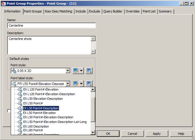
03/04/2014 2.05 © Copyright (2014) Wetland Studies and Solutions, Inc. Do not reproduce without permission. 34In the Point Group Properties dialog, supply a Name for the first new point group - Centerline. Also
add a Description.
Selecting Point Styles
The Point style, currently set to 0.10 X 3D in both the point group defaults and in the Description
Key for the centerline shots is simply too big. Select a different one which is smaller, 0.05 X 3D, from
the dropdown list.
Figure 1.63 - Point Style Selection
To look at some of the parameters in this Point Style click the glyph adjacent to the Point Style
selection as shown, and click Edit Current Selection from the menu.
Figure 1.64 - Edit Current Selection on Point Style
03/04/2014 2.05 © Copyright (2014) Wetland Studies and Solutions, Inc. Do not reproduce without permission. 35There are a lot of components to an object style in Civil 3D, and they will be covered in much more
detail in later chapters.
To look at the pertinent components of the Point Style, begin on the Marker tab.
The Marker selection in this style is a Custom Marker, X shaped, as opposed to an AutoCAD
block. This accounts for part of the style name, 0.05 X 3D. Many of the styles in use in the description
keys utilize blocks, rather than markers. To be used, the blocks must reside in the drawing, and cannot
be obtained from an outside location.
Land Desktop could pull in Description Key blocks from an external location, usually the Symbol
Manager files. Civil 3D cannot.
The Size option for this style is set to Use drawing scale, and the size is set to 0.05" plotted height.
The point styles have annotative behavior as the drawing scale is changed, so this establishes the size in
plotted units regardless of drawing scale. This also explains another part of the style name, 0.05 X
3D.
Figure 1.65 - Point Style Dialog, Marker Tab
Click over to the 3D Geometry tab in the Point Style dialog.
03/04/2014 2.05 © Copyright (2014) Wetland Studies and Solutions, Inc. Do not reproduce without permission. 36On the 3D Geometry tab, the Point Display Mode is set to Use Point Elevation. This means that
the point will sit in the drawing in 3D, at an actual Z value corresponding to the elevation value on the
point. This means that any AutoCAD objects drawn by snapping to the points will be in 3D, essential for
breakline construction. This also explains the other element of the style name, 0.05 X 3D.
In some instances it is desirable to have points displayed in the drawing in 2D rather than 3D; an
example would be traverse points where a quick inverse is desired by snapping from point to point. For
an application such as this the Point Display Mode would be set to Flatten Points to Elevation,
and the Point Elevation value would be set to 0. The 0.05 X 2D and 0.10 X 2D styles behave this
way, as do a number of other styles in use with Description Keys.
We'll turn you lose to explore the styles used in the Description Keys shortly.
Figure 1.66 - Point Style Dialog, 3D Geometry Tab
Press OK to exit the Point Style dialog, returning to the Point Group Properties dialog.
In editing styles from within settings dialogs in Civil 3D it's possible to get about six levels deep in
dialogs. If LISP stands for Lost In Stupid Parentheses, Civil 3D should be characterized by LIED - Lost In
Endless Dialogs.
03/04/2014 2.05 © Copyright (2014) Wetland Studies and Solutions, Inc. Do not reproduce without permission. 37You can also read