Launch: payload USER'S GUIDE - August 2020 Version 6.5 - Rocket Lab
←
→
Page content transcription
If your browser does not render page correctly, please read the page content below
launch:
payload
USER'S
GUIDE
Aug us t 2020
Vers ion 6.5

          AUGUST 2020 | VERSION 6.5 1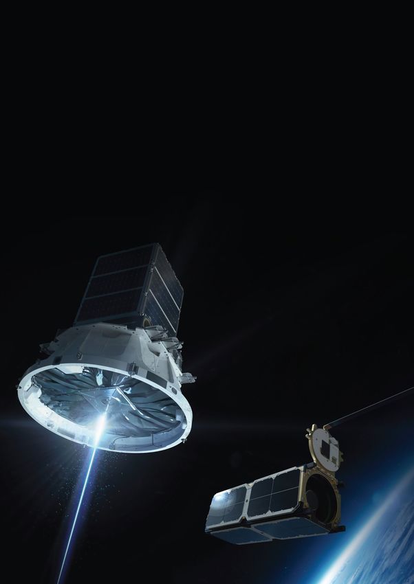
U n p r e c e d e n t e d a c c e s s t o s pa c e

                                                     opening access to space
                                                     Small satellites are shaping the way we use space to innovate, explore and improve life
                                                     on Earth. Historically it has been slow, expensive, and challenging to get these small but
                                                     incredibly capable spacecraft to orbit. Our Electron launch vehicle changed that, and
                                                     revolutionized access to space.
                                                     Rocket Lab is enabling companies, students, scientists, researchers, governments and
                                                     entrepreneurs alike to get their ideas to orbit right now. A solar system of possibilities has
                                                     opened up for people who thought space was out of reach, until now. The satellites we
                                                     launch are keeping countries connected and borders protected, they're monitoring weather
                                                     and managing waste, they're providing insights on climate change, and helping us manage
                                                     resources for future generations.

                                                     We believe getting to space should be easy, which is why we developed a launch experience
                                                     like no other. Every detail of Electron has been designed for rapid production to support
                                                     frequent and reliable launch for small satellites. Since our first launch in 2017, Electron has
                                                     become one of the world’s most frequently launched orbital vehicles. To give small satellite
                                                     operators unmatched control over their launch schedule, we also operate three launch pads
                                                     across the United States and New Zealand that can support more than 130 launches every
                                                     year.

                                                     Every aspect of the launch process has been streamlined to make your mission simple and
                                                     seamless, from idea to orbit.

                                                     Tell us about your mission. We look forward to making it a reality.

                                                     Peter Beck
                                                     Founder and Chief Executive of Rocket Lab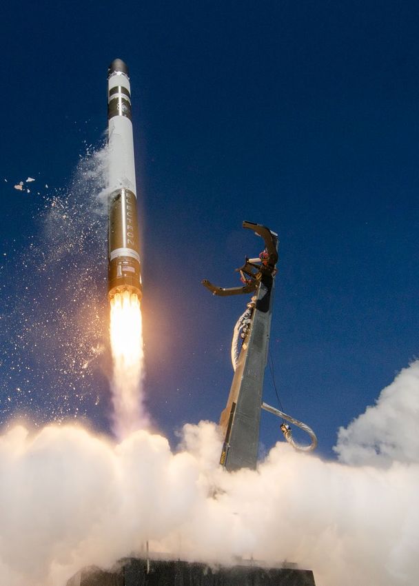
pay l o a d u s e r s g u i d e o v e r v i e w

                                                  Launch: Payload
                                                  USER’S GUIDE OVERVIEW
                                                  This document is presented as an introduction to the launch services available
                                                  on the Electron Launch Vehicle. It is provided for planning purposes only and is
                                                  superseded by any mission specific documentation provided by Rocket Lab.

                                                  Revision History

                                                  DATE                VERSION         HISTORY
                                                  June, 2015          1.0             First Release
                                                  May, 2016           2.0             Updated Release
                                                  September, 2016     3.0             Updated Release
                                                  December, 2016      4.0             Updated Release
                                                  April, 2017         5.0             Updated Release
                                                  June, 2018          6.0             Updated Release
                                                  July, 2018          6.1             Updated Release
                                                  August, 2018        6.2             Updated Release
                                                  April, 2019         6.3             Updated Release
                                                  June, 2019          6.4             Updated Release
                                                  August, 2020        6.5             Updated Release

                                                  contact rocket lab
                                                    rocketlabusa.com
                                                    launch@rocketlabusa.com
                                                    + 1 (714) 465 5737

                                                                                                                     AUGUST 2020 | VERSION 6.5 3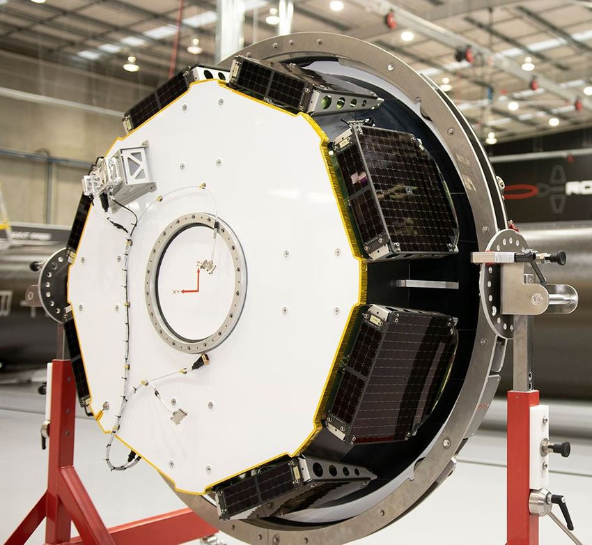
TABLE OF CONTENTS
TA B L E O F C O N T E N T S

                               1 MEET ELECTRON...................................2                   Random Vibration......................................... 31
                               Key Features of Electron..................................4           Venting.........................................................32
                               Sample Electron flight profile........................... 7
                                                                                                     7 LAUNCH SITES & FACILITIES................. 33
                               2 THE KICK STAGE.....................................8                Safety & Security ..........................................41
                               Kick Stage Specifications............................... 10
                                                                                                     8 PAYLOAD & LAUNCH OPERATIONS....... 42
                               3 PERFORMANCE OVERVIEW.................. 13                           Standard services..........................................44
                               Electron Vehicle Performance......................... 14              Non-standard services...................................44
                               Orbit Injection Accuracy................................. 15          Payload processing facilities..........................46
                               Attitude & Deployment Rates........................16                 Transportation.............................................. 50
                               4 AVIONICS............................................. 17            Launch operations schedule..........................50
                                                                                                     Post-launch reporting.................................... 51
                               5 PAYLOAD ACCOMMODATION............... 19
                                                                                                     Mission integration schedule.........................54
                               The Fairing....................................................20
                               Payload Plate................................................22       10 MEET THE TEAM.................................. 55
                               Payload Electrical Interfaces......................... 23             13 QUICK REFERENCE GUIDE.................. 57
                               Seperation Systems......................................24            List of Figures................................................ 57
                               6 FLIGHT ENVIRONMENTS..................... 26                         List of Tables.................................................58
                               Acceleration Loads........................................28          List of Acronyms...........................................59
                               Shock...........................................................29
                               Acoustic........................................................ 30
                               Radio Frequency (RF).................................... 30

                                                                                                                                                   AUGUST 2020 | VERSION 6.5 01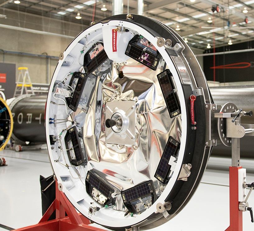
1. meet
                               ELECTRON
        MEET ELECTRON

                                 your ride to orbit.

02 AUGUST 2020 | VERSION 6.5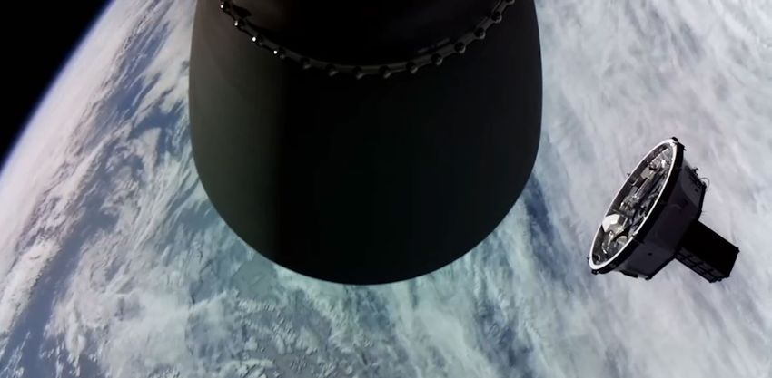
Your ride to orbit
Electron (Figure 1) is an orbital launch vehicle designed specifically to place small satellites
of up to 300 kg / 660 lbm into a wide range of low Earth orbits (LEO). Every aspect of
yo u r r i d e t o o r b i t
Electron has been designed for frequency and reliability to meet the evolving needs of
government and commercial small satellite operators.
Flight Heritage
Since its first launch in 2017, Electron has become the leading launch vehicle dedicated to
small satellites and one of the most frequently launched orbital rockets in the world. More
than 50 satellites have been deployed to orbit by Electron for commercial and government
partners, including NASA, the U.S. Air Force, DARPA, and the National Reconnaissance Office.
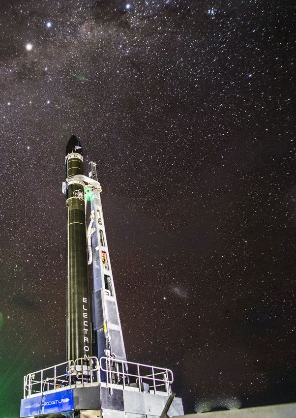
Figure 1 Electron lifts off from Rocket Lab LC-1 Pad A
Electron overview
Designed, manufactured, and launched by Rocket Lab, Electron is a two-stage
launch vehicle powered by liquid oxygen (LOx) and rocket-grade kerosene (RP-1). By
incorporating an orbital transfer vehicle stage (Kick Stage) that can deploy multiple
payloads to unique orbits on the same mission, Electron can support dedicated missions
and rideshare options without the complexity and schedule risk typically associated with
launching on medium or heavy lift launch vehicles.
Electron utilizes advanced carbon composite technologies throughout the launch
vehicle structures, including all of Electron’s propellant tanks. The all carbon-composite
construction of Electron decreases mass by as much as 40 percent compared with
traditional aluminum launch vehicle structures, resulting in enhanced vehicle performance.
Rocket Lab fabricates tanks and other carbon composite structures in-house to improve
cost efficiency and drive rapid production.
Electron is powered by the in-house designed and produced additively manufactured
Rutherford engines. Since its first launch in 2017, Rocket Lab has released additional
performance from Rocket Lab’s Rutherford engines boosting the Electron’s total payload
lift capacity up to 300 kg / 660 lbm.
AUGUST 2020 | VERSION 6.5 03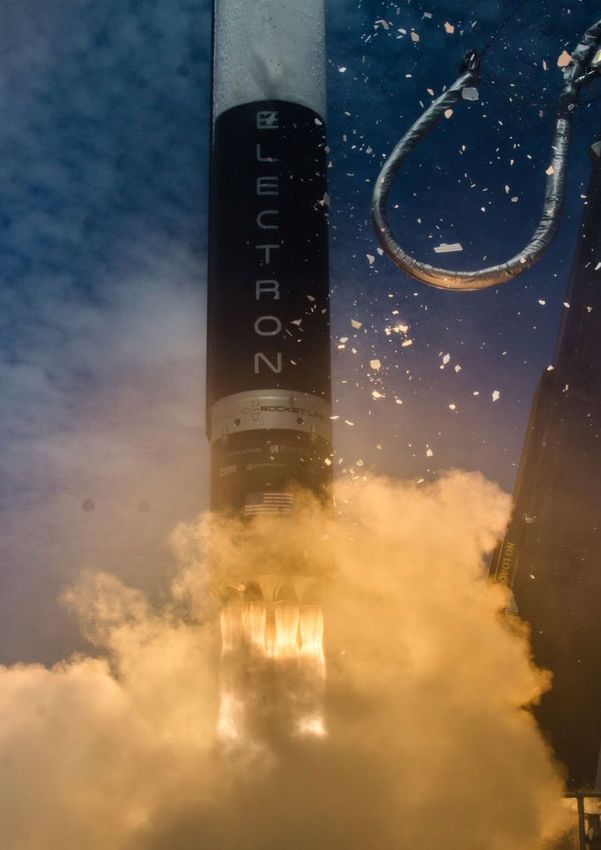
Fairing

                                                                    Kick stage

                                             Payload plate
       ta k e a l o o k i n s i d e

                                                                    SECOND stage

                                      RUTHERFORD VACUUM ENGINE

                                                                  INTERSTAGE

     OV E R A L L
     LENGTH
     18M
     DIAMETER (MAX)
     1.2M
     STAGES
     2 + KICK STAGE
     VEHICLE MASS (LIFTOFF)
     13,000KG
     MATERIAL/STRUCTURE
     CARBON FIBER COMPOSITE/MONOCOQUE
     PROPELLANT
     LOX/KEROSENE

     PAY L OA D
     NOMINAL PAYLOAD
     200kg / 220lbm to 500km SSO                                  FIRST STAGE
     PAYLOAD DIAMETER
     1.08M
     PAYLOAD HEIGHT
     1.91M
     FAIRING SEP SYSTEM
     Pneumatic UNLOCKING, SPRINGS

     S TAG E 2
     PROPULSION
     1X RUTHERFORD VACUUM ENGINE
     THRUST
     5800 LBF VACUUM
     ISP
     343 SEC

     I N T E R S TAG E
     SEPARATION SYSTEM
     Pneumatic Pusher

     S TAG E 1
     PROPULSION
     9X RUTHERFORD SEA LEVEL ENGINES                                  POWER PACK
     THRUST
     5600 LBF SEA LEVEL (PER ENGINE)
     ISP
     311 SEC                                                     9x Rutherford Sea Level Engines

04 AUGUST 2020 | VERSION 6.5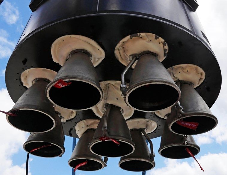
First Stage
                               Electron’s first stage consists of nine sea-level Rutherford engines, linerless common
                               bulkhead tanks for LOx and RP-1, and an interstage.
                               Rocket Lab’s flagship engine, the 5,600 lbf (24 kN) Rutherford, is an electric pumped LOx/
                               kerosene engine specifically designed for the Electron launch vehicle. Rutherford adopts
                               an entirely new electric propulsion cycle, making use of brushless DC electric motors and
                               high-performance lithium polymer batteries to drive its propellant pumps. This cuts down
yo u r r i d e t o o r b i t

                               on much of the complex turbomachinery typically required for gas generator cycle engines,
                               meaning that the Rutherford is simpler to build than a traditional engine but can achieve
                               90% efficiency. 130 Rutherford engines have been flown to space on Electron as of July 2020.
                               Rutherford is also the first oxygen/hydrocarbon engine to use additive manufacturing
                               for all primary components, including the regeneratively cooled thrust chamber, injector
                               pumps, and main propellant valves. The Stage 1 and Stage 2 Rutherford engines are
                               identical, with the exception of a larger expansion ratio nozzle for Stage 2 for improved
                               performance in near-vacuum-conditions. All aspects of the Rutherford engines are
                               completely designed in-house and are manufactured directly at our Long Beach
                               headquarters in California, USA.

                               Figure 2 First Stage      Figure 3 Rutherford Stage 1 Configuration
                               Rutherford Engine

                               Second Stage
                               Electron’s second stage consists of a single vacuum optimized Rutherford engine, and
                               linerless common bulkhead tanks for LOx and kerosene. With an expanded nozzle, Electron’s
                               second stage engine produces a thrust of 5,800 lbf and has a specific impulse of 343 sec.
                               The 1.2 m diameter second stage has approximately 2,000 kg of propellant on board. The
                               Electron Stage 2 has a burn time of approximately five minutes with a Rutherford vacuum
                               engine as it places the Kick Stage into orbit.
                               High Voltage Batteries (HVBs) batteries provide power to the LOx and kerosene pumps
                               for the high-pressure combustion while a pressurant system is used to provide enough
                               pump inlet pressure to safely operate. During the second stage burn, two HVBs power
                               the electric pumps until depletion, when a third HVB takes over for the remainder of the
                               second stage burn. Upon depletion, the first two HVBs are jettisoned from Electron to
                               reduce mass and increase performance in flight.
                               The engine thrust is directed with electromechanical thrust vector actuators in two axes.
                               Roll control is provided via a cold gas reaction control system (RCS).

                                                                                                            AUGUST 2020 | VERSION 6.5 05
Kick Stage
                                      Rocket Lab’s Kick Stage offers our customers unmatched flexibility for orbital deployment.
                                      The Kick Stage is a third stage of the Electron launch vehicle used to circularize and raise
                                      orbits to deploy payloads to unique and precise orbital destinations. The Kick Stage is
                                      powered by Rocket Lab’s in-house designed and built Curie engine.
                                      In its simplest form, the Kick Stage serves as in-space propulsion to deploy payloads to
       yo u r r i d e t o o r b i t

                                      orbit. It its most advanced configuration the Kick Stage becomes Photon, Rocket Lab’s
                                      satellite bus that supports several-year duration missions to LEO, MEO, Lunar, and
                                      interplanetary destinations. Comprehensive information about the Kick Stage can be
                                      found on page 9.

                                      Figure 4 The Kick Stage in orbit prior to payload deployment, 2019

                                      Fairing
                                      Electron’s payload fairing protects the payload from encapsulation through flight. Electron’s
                                      payload fairing is a composite split clam shell design and includes environmental control for
                                      the payload. During separation, each half of the fairing is designed to rotate on a hinge away
                                      from the payload, resulting in a safe separation motion.

                                      Figure 5 Rocket Lab's fairing in clean room 1
                                      after encapsulation at Launch Complex 1

06 AUGUST 2020 | VERSION 6.5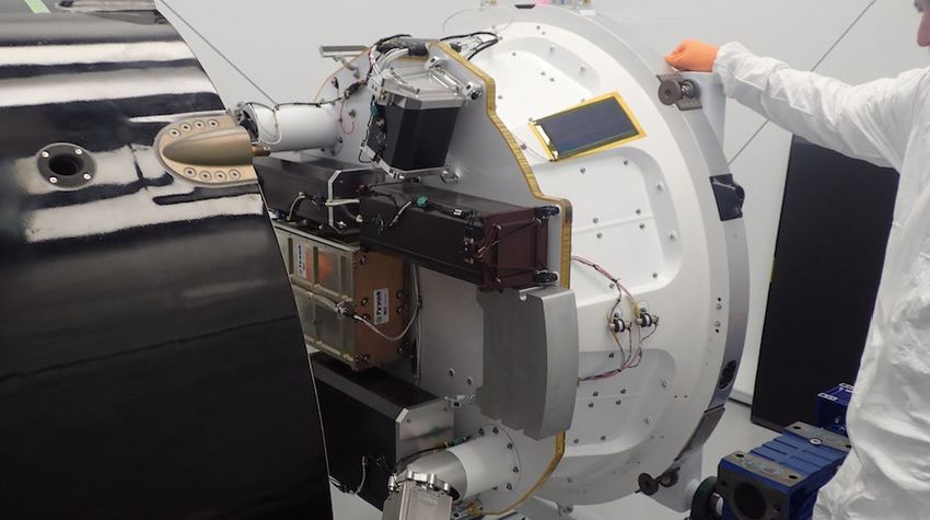
Sample Electron
                                        Flight Profile
yo u r r i d e t o o r b i t

                                        In this example flight profile (figure 6), payload deployment occurs approximately 3,000
                                        seconds after liftoff for a standard dedicated mission to low Earth orbit. In this scenario,
                                        Electron’s second stage inserts the Kick Stage into a low elliptical orbit, before the Kick
                                        Stage initiates a burn of the Curie engine to circularize into the final orbit. For rideshare
                                        missions requiring multiple deployments, as well as those requiring higher orbits, the Kick
                                        Stage performs multiple engine burns to raise orbits and deploy to different, precise orbits
                                        for each payload.

                                                                                                        L+ 539 secs           As required per mission

                                                                                                                                                    As required per mission   As required per mission
                                                                                          L+ 388 secs
                                                                                                                L+ 535 secs

                                     L+ 162 secs                      L+ 184 secs
                               Altitude: ~82 km                       Altitude: ~126 km

                                                   L+ 158 secs
                                                   Altitude: ~78 km

              L+ 155 secs
                Altitude:

                                                                            Figure 6 Electron example flight profile

                                                                                                                                                                       AUGUST 2020 | VERSION 6.5 07
2. THE
KICK STAGE
m e e t T H E K I C K S TA G E
Unrivaled flexibility for
precise orbital deployment.
08 AUGUST 2020 | VERSION 6.5unmatched flexibility for
orbital deployment
M E E T T H E K I C K S TA G E
The Rocket Lab Kick Stage is designed to deliver small satellites to precise and unique
orbits, whether flying as dedicated or rideshare on Electron.
The Kick Stage enables missions that require:
• Deployment of payloads at multiple planes/inclinations, including constellations
• Higher altitude deployment
• Inclinations out of range of the launch vehicle
• Hosted payload support
• Multiple trajectory changes
• Sustained low altitude orbits
• Deorbiting
Figure 7 Rocket Lab's Kick Stage being intergrated with the fairing
The Kick Stage is powered by the in-house designed and manufactured Curie engine, a
high-energy additively manufactured engine powered with a green bi-propellant. The Kick
Stage also employs a cold gas reaction control system to precisely point itself and deploy
satellites to independent yet highly precise orbits, and eliminate the risk of recontact with
other spacecraft during deployment.
AUGUST 2020 | VERSION 6.5 09Kick Stage specifications
Height 405 mm
Diameter 1.2 m
Dry mass 40 kg / 88 lbs (dry)
m e e t T H E K I C K S TA G E
Material Carbon composite
Engine Curie
Propellant Liquid bi-propellant
Propellant storage Carbon composite tanks
Number of thrusters 6 reaction control thrusters (RCS) (2 pods)
Thrust 120 N
Table 1 Kick Stage Specifications
In its simplest form, the Kick Stage serves as in-space propulsion to deploy payloads to
orbit. In its most advanced configuration the Kick Stage becomes Photon, Rocket Lab’s
satellite bus that supports several-year duration missions to LEO, MEO, Lunar, and
interplanetary destinations.
ENVELOPE
FAIRING
36.75in
5.44in 933.4mm
138.1mm 15.16in
385.0mm
16.50°
Kickstage
2.78in
70.5mm
0
Figure 8 Rocket Lab's Kick Stage
47.39in
1203.6mm
inside the fairing envelope
10 AUGUST 2020 | VERSION 6.5Deorbiting
As the small satellite industry experiences rapid growth, Rocket Lab is determined to
be part of the solution for sustainability and the reduction of orbital debris in space.
Traditional methods of deploying satellites can leave large rocket stages in orbit,
contributing to the global issue of space debris. The Kick Stage has been designed with
the capability to deorbit itself on an accelerated time scale, well before the 25 year deorbit
M E E T T H E K I C K S TA G E
guidelines stipulated by NASA. By performing a deorbit burn with the Curie engine,
Rocket Lab can lower the Kick Stage’s perigee to increase aerodynamic drag on the
spacecraft and cause it to deorbit within months or single digit years, as required.
AUGUST 2020 | VERSION 6.5 11Extended missions
For missions that require extended payload support on orbit, or for missions exceeding
2,000 km to MEO, lunar, or interplanetary destinations, Rocket Lab offers the Photon
spacecraft bus, a high-performance evolution of the Kick Stage. Photon is a configurable,
modular spacecraft designed to accommodate a variety of payloads and instruments
without significant redesign. Photon is equipped with radiation-tolerant avionics, deep
M E E T T H E K I C K S TA G E
space-capable communications and navigation technology, and high-performance
space-storable propulsion capable of multiple restarts on orbit. With the capacity to
both host an external payload and perform secondary mission objectives as a separate
operational spacecraft, Photon has been designed for dedicated mission or as a rideshare
option without the programmatic complexity, expanded cost, and schedule risk typically
experienced when launching with a medium or heavy lift launch vehicle. For more
comprehensive information about Photon, please contact the Rocket Lab team via
launch@rocketlabusa.com
Figure 9 Photon LEO configuration Figure 10 Photon LEO configuration
(propulsion angle) (payload plate view)
Figure 11 Photon interplanetary configuration
12 AUGUST 2020 | VERSION 6.5p e r f o r m a n c e ov e rv i e w
3. performance
overview
Elegant design.
Exceptional performance.
AUGUST 2020 | VERSION 6.5 13P E R F O R M A N C E OV E RV I E W
Electron vehicle
performance
Electron is designed to place payloads of up to 200 kg into a circular SSO at 500 km altitude,
however we can accommodate a wide range of different payload and orbit requirements.
One of the most common orbits requested by customers is a Sun-synchronous orbit (SSO),
which is shown in Figure 12.
Rocket Lab operates two launch sites; Launch Complex 1 on New Zealand’s Māhia Peninsula,
and Launch Complex 2 within the Mid-Atlantic Regional Spaceport at the NASA Wallops
Flight Facility in Virginia.
From Launch Complex 1, Electron can be flown on trajectories of inclinations ranging from
39 degrees to 120 degrees. Additional inclinations outside of this range may also be possible
upon request.
From Launch Complex 2, Electron can be flown on trajectories of inclinations ranging from
38 degrees to 60 degrees. Additional inclinations outside of this range may also be possible
upon request.
ELECTRON PERFORMANCE CURVES
Payload mass (kg)
Circular Altitude (km)
Figure 12 Performance to Circular Orbits
14 AUGUST 2020 | VERSION 6.5P E R F O R M A N C E OV E RV I E W
For customers seeking non-traditional orbits, Figure 13 below represents the maximum
performance for an elliptical orbit launched due east from the Mahia launch site.
ELLIPTICAL ORBIT: PAYLOAD VS APOGEE
(PERIGEE: 180 KM, INCLINATION: 39°)
315
310
Mass to Orbit (kg)
305
300
295
290
285
300 350 400 450 500 550 600 650 700 750 800
Apogee altitude (km)
Figure 13 Performance to a 180 km Perigee at 39° Inclination Elliptical Orbit
Orbit injection accuracy
Electron can achieve the following target mission injection accuracies for a typical mission to
500 km SSO, as shown in Table 2. Note that mission-specific payload injection accuracies will
be calculated as part of mission analysis at Rocket Lab.
Inclinations +/- 0.15 deg
Perigee +/- 15 km
Apogee +/- 15 km
Table 2 Orbit Injection Accuracy
AUGUST 2020 | VERSION 6.5 15P E R F O R M A N C E OV E RV I E W
Attitude and
Deployment rates
Electron can achieve the following target mission injection accuracies for a typical mission to
500 km SSO, as shown in Table 3. Note that mission-specific payload injection accuracies will
be calculated as part of mission analysis at Rocket Lab.
Attitude +/- 5 deg
Rates +/- 1.5 deg/s
Table 3 Deployment Rates
The onboard cold gas thruster attitude reaction control system (RCS) of the Kick Stage
will provide the capability to hold a nominal attitude prior to separation of the payload,
resulting in low deployment attitude and rate margins. Mission-specific values will be
provided by Rocket Lab.
16 AUGUST 2020 | VERSION 6.54. avionics
High-performance flight
computer systems.
AV I O N I C S
AUGUST 2020 | VERSION 6.5 17high-performance flight
computer systems
Rocket Lab has designed high-performing avionics and flight computer systems, including
in-house assembly and testing. The computing nodes make use of state-of-the-art Field
Programmable Gate Array (FPGA) architecture, allowing massive customization of
AV I O N I C S
function while retaining hardware commonality.
Rocket Lab performs avionics validation not only at the component level, but also in our
sophisticated hardware-in-the-loop (HITL) test facility which allows for integrated launch
vehicle and software simulation and testing.
The Electron launch vehicle is equipped with a proven, Federal Aviation Authority (FAA)
certified autonomous flight termination system which has been in use on Electron since
2019. The system safely terminates the flight of the vehicle automatically if mission rules
are violated.
Figure 14 Rocket Lab Avionics
18 AUGUST 2020 | VERSION 6.5PAY L O A D A C C O M M O D AT I O N
5. PAYLOAD
ACCOMMODATION
make yourself at home.
AUGUST 2020 | VERSION 6.5 19THE FAIRING
PAY L O A D A C C O M M O D AT I O N
Electron’s payload fairing is a composite split clam shell design and includes environmental
control for the payload. During separation, each half of the fairing is designed to rotate on a
hinge away from the payload, resulting in a safe separation motion.
[ 10.96 ]
¯ 278.3
[ 75.77 ]
1924.6
[ 16.65 ]
[ 69.83 ] 423.0
1773.7
[ 21.74 ]
[ 63.89 ] 552.3
1622.7
[ 26.26 ]
[ 57.94 ] 667.0
1471.8
[ 30.23 ]
[ 52.00 ] 767.9
1320.8
[ 33.68 ]
[ 46.06] 855.4
1169.9
[ 36.62 ]
[ 40.12 ] 930.0
1018.9
[ 39.06 ]
[ 34.17 ] 992.2
868.0
[ 41.03 ]
[ 28.23 ] 1042.1
717.0
[ 42.13 ]
[ INCHES ] ¯ 1070.0
MILLIMETRE
Figure 15 Fairing capacity & sample configuration inside of the fairing
S P E C I F I C AT I O N VA L U E
Length 2.5 m
Diameter (maximum) 1.2 m
Mass 44 kg
Acoustic Protection Foam Sheets
Separation System Pneumatic Unlocking, Springs
Table 4 Electron fairing specifications
20 AUGUST 2020 | VERSION 6.5EXPANDED FAIRING OPTIONS
PAY L O A D A C C O M M O D AT I O N
Rocket Lab can develop custom solutions for customers with payloads that exceed the
standard envelope.
To explore an expanded fairing option for your mission, contact the Rocket Lab team via
launch@rocketlabusa.com.
Expanded fairings are a non-standard service and are only available for missions with a
mission integration schedule exceeding 12 months.
Standard Expanded
Electron Electron
Fairing Fairing
Figure 16 Standard Electron Fairing Figure 17 Expanded Electron Fairing
AUGUST 2020 | VERSION 6.5 21PAY L O A D A C C O M M O D AT I O N
PAYLOAD PLATE
The primary means of attachment between the Electron launch vehicle and the customer
payload is via the Payload Plate, which typically forms the direct interface between the
spacecraft separation system and the launch vehicle. For rideshare missions, multiple
spacecraft separation systems may be mounted directly to the payload plate or Rocket
Lab may recommend the use of a multiple payload adapter, to make best use of the
available space within the fairing. Customers can provide their own adapters or Rocket Lab
can provide one as a non-standard service.
Approximately 1 m in diameter, Rocket Lab’s Payload Plate is a honeycomb composite
structure which is customized with an interface bolt pattern specifically to match the
customer’s requirements. Payload Plate configurations can be customized to accept single or
multiple satellites, independent of whether they are CubeSat or microsatellite form factors.
Figure 18 Rocket Lab payload plate
22 AUGUST 2020 | VERSION 6.5PAY L O A D A C C O M M O D AT I O N
Figure 19 Rocket Lab payload plate, payload configuration for NASA ELaNa-19 mission
Payload Electrical
Interfaces
The Electron offers a Standard Electrical Interface Panel (SEIP) for connecting one or more
spacecraft separation systems. Details of this interface are provided in the mission specific
ICD. As a non-standard service, a payload electrical umbilical, available from spacecraft mate
to the launch vehicle, through day of launch, is available for customer use. The umbilical
provides up to ten twisted shielded pairs and ethernet connectivity, allowing Customers to
charge and monitor spacecraft during integration and post-encapsulation. If this service is
utilized, an electrical ground support equipment interface panel will be accessible in the client
room, hangar and in a customer equipment room near the launch pad. Umbilical harness
specifications will be defined in the mission specific ICD and provided in accordance with
contractual requirements.
AUGUST 2020 | VERSION 6.5 23PAY L O A D A C C O M M O D AT I O N
Separation systems
For CubeSat customers, Electron has been designed to support all commercially available
payload separation systems, both mechanically and electrically. Electron has the added
capability to deploy multiple separation systems during a single mission, enabling rideshare
missions without additional sequencer hardware. Rocket Lab can procure the separation
system on a customer’s behalf, integrate a customer supplied system, or supply a Rocket
Lab-developed separation system – such as our Maxwell series of CubeSat dispensers.
For microsatellites customers Electron is designed to support the RUAG Clamp-band,
Planetary Systems Corp Motorized Light-band and 4-point Hold Down separation systems.
Please contact Rocket Lab for compatibility of other separation systems.
Rocket Lab has worked with RUAG to offer the PAS 381S separation system. The PAS 381S
is perfectly sized for Electron-class dedicated payloads and is cross compatible with the
standard 15" ESPA interface that many small satellites have been designed to. The PAS
381S can be configured for flight in advance of the spacecraft arrival at the launch site, so
all that remains is the installation of bolts at the mechanical interface and any required
electrical connections or hookups. The RUAG PAS 381S for Electron has also been designed
to accommodate a fly-away electrical umbilical interface, for those customers who require
power or connectivity during post-encapsulation and on-pad operations.
Figure 20 PAS 381S separation system
24 AUGUST 2020 | VERSION 6.5PAY L O A D A C C O M M O D AT I O N
Rocket Lab has worked with Planetary Systems Corp (PSC) to offer multiple Motorized Light-
Band (MLB) diameters specifically suited to the footprint of the spacecraft. The MLBs that are
compatible with the Electron mechanical interface are 8” through 24” diameters. The MLB
integration at the launch site utilizes Rocket Lab or customer provided standard electrical
test hardware compatible with all MLB’s and the PSC CSD CubeSat dispenser available from
PSC. The MLBs for Electron have also been designed to accommodate a fly-away electrical
umbilical interface, for those customers who require power or connectivity during post-
encapsulation and on-pad operations.
Figure 21 PSC Motorized Light Band (MLB) separation system
AUGUST 2020 | VERSION 6.5 256. flight
FLIGHT ENVIRONMENTS
environments
The smoothest ride to orbit.
26 AUGUST 2020 | VERSION 6.5FLIGHT ENVIRONMENTS
The smoothest ride to orbit
Electron’s payload environments provide the most secure and smooth ascent to orbit on the
market.
Rocket Lab can perform a mission specific Integrated Thermal Analysis (ITA) as part of the
launch service statement of work on request, including incorporating data from previous
flights to further refine launch environments. The loads and environments provided in this
section are for reference only – final mission environments are provided to customers via
the mission specific interface control document (ICD). The environments represent the flight
level maximum predicted environment (MPE) at the top of the payload plate and do not
include any additional margin for testing of spacecraft. Rocket Lab recommends customers
follow the guidelines in GSFC-STD-7000 for spacecraft testing margins.
Fairing Thermal and
Humidity Environment
The fairing environment is controlled from encapsulation through deployment, with a
maximum relative humidity of 65%. A standard mission will experience free molecular
heating around 1135 W/m^2 at fairing deployment.
Rocket Lab can perform a mission specific thermal analysis encompassing events from roll-
out to orbital deployment on request.
AUGUST 2020 | VERSION 6.5 27FLIGHT ENVIRONMENTS
Acceleration loads
The payload will be subjected to a range of axial and lateral accelerations during flight. The
maximum predicted load factors will typically be within the envelope shown in the Figure
below. This envelopes both static and dynamic loads. Mission specific accelerations will be
determined via coupled loads analysis and provided in the mission ICD.
Figure 22 Electron Acceleration MPE
28 AUGUST 2020 | VERSION 6.5FLIGHT ENVIRONMENTS
Shock
The maximum predicted shock response at the Payload Plate from all sources of launch
vehicle shock is shown below in Figure 23 and Table 6.
Figure 23 Electron Shock MPE
frequency(hz) s r s a c c e l e r at i o n
100 50
900 700
10000 700
Table 5 Electron Shock MPE
AUGUST 2020 | VERSION 6.5 29acoustics
The maximum predicted acoustic environment within the Payload Fairing will be at or below
FLIGHT ENVIRONMENTS
the levels shown in Figure 24, below.
122.9 dBOA
Figure 24 Electron Acoustic MPE
Radio Frequency
Electron radiates radio frequency emissions in three frequency bands. These emissions come
from omnidirectional antennas mounted around and under the ring of the Kick Stage and
from the body of the lower stages. Payloads can expect to experience an electric field from
these emissions no worse than the levels in the table below. Some frequency adjustments
may be able to occur within these bands to accomplish inter-compatibility if required.
Frequency Operating Electron Antenna to E-field During
Band (MHz) Period Mounted Payload (mm) Launch (V/m)
401-402 Orbital Phase 150 41.7
2200-2290 Entire Mission 350 15.6
2360-2395 Boost Phase 500 24.5
Table 6 The worst case radiated emissions during launch and at the time of payload activation
30 AUGUST 2020 | VERSION 6.5Random Vibration
FLIGHT ENVIRONMENTS
The curves below specify the Maximum Predicted Random Vibration Environment for
CubeSat and MicroSat class payloads integrated to the Electron launch vehicle. The levels
combine predicted environments and flight data, and are supplied at the spacecraft
interface. Customer specific test levels and notching strategies will be reviewed by Rocket
Lab on a mission specific basis.
CubeSat Class MPE: Applicable for satellites with a total mass no greater than 30 kg.
MicroSat Class MPE: Applicable for satellites with a total mass greater than 30 kg.
Figure 25 Electron Random Vibration MPE
AUGUST 2020 | VERSION 6.5 31venting
FLIGHT ENVIRONMENTS
The fairing compartment depressurization rate is less than 2.0 kPa/sec, apart from a short
period during transonic flight with a duration of no longer than 5 seconds. The maximum
depressurization rate during transonic flight is no greater than 3.7 kPa/sec. A typical profile
of depressurization rate and absolute pressure in the fairing are provided, but is subject to
specific trajectory.
Figure 26 Electron Typical Fairing Venting Environment
32 AUGUST 2020 | VERSION 6.5L a u n c h S i t e s a n d Fac i l i t i e s
7. Launch Sites
and Facilities
AUGUST 2020 | VERSION 6.5 33L a u n c h S i t e s a n d Fac i l i t i e s
Launch Sites
Rocket Lab operates two launch sites comprising a total of three pads for the Electron
launch vehicle. Between the two sites, located in Māhia, New Zealand, and Virginia, Rocket
Lab offers more than 130 launch opportunities every year. This means our customers enjoy
unmatched flexibility for their launch location and schedule.
Launch Complex 1,
Mahia, New Zealand
Rocket Lab operates the world’s only private orbital launch range, Launch Complex 1. The
Māhia Peninsula-based complex is licensed by the FAA and can support up to 120 launches
per year. The site is located at (39.262°S, 177.865°E) in the Hawke’s Bay, New Zealand.
Rocket Lab operates two pads at Launch Complex 1; Pad A and Pad B. The operation of
two launch pads within the launch complex eliminates the time currently required between
launches for a full pad recycle. This enables truly responsive launch opportunities, providing
Rocket Lab with the ability to launch back-to-back within hours – not days, weeks or months.
Figure 27 Rocket Lab's Launch Complex 1, Pad A
34 AUGUST 2020 | VERSION 6.5L a u n c h S i t e s a n d Fac i l i t i e s
Auckland Test Facilities and
Auckland Production Complex
Launch Complex 1
Figure 28 New Zealand Locations
LC-1 Pad B
Offices
Vehicle Integration
Facility & Cleanrooms
LC-1 Pad A
Figure 29 Launch Complex 1 Layout
The launch site also includes a Command and Control Facility located 2.5 km from the launch
pad. This location houses workstations for flight safety, payloads, launch vehicle teams, and
the launch director. This is also the location of the tracking antennas on the day of launch,
supported by a downrange facility on the Chatham Islands.
AUGUST 2020 | VERSION 6.5 35L a u n c h S i t e s a n d Fac i l i t i e s
Figure 30 Electron at Launch Complex 1 - Pad A
Figure 31 Electron inside Launch Complex 1's Vehicle Integration Facility
36 AUGUST 2020 | VERSION 6.5L a u n c h S i t e s a n d Fac i l i t i e s
Launch Complex 2,
Wallops Island, VA, USA
Rocket Lab operates a launch site for the Electron launch vehicle from a dedicated pad
located at the Mid-Atlantic Regional Spaceport within the NASA Wallops Flight Facility in
Virginia. Launch Complex 2 represents a new responsive launch capability for the United
States on home soil.
The complex is tailored for U.S. government small satellite missions, but it can support
commercial missions as required. Launch Complex 2 can support up to 12 missions per year.
The site is located at 37. 834°N, 75.488°W and can support launches to inclinations between
38 and 60 degrees.
Figure 32 Launch Complex 2's Location
Rocket Lab also operates an Integration and Control Facility (ICF) within the Wallops
Research Park. This facility is dedicated to secure vehicle and payload processing facilities.
The facility can process several Electron vehicles concurrently, enabling rapid and
responsive launch opportunities.
AUGUST 2020 | VERSION 6.5 37L a u n c h S i t e s a n d Fac i l i t i e s
Figure 33 Electron at Launch Complex 2 Figure 34 Electron at Launch Complex 2
Rocket Lab ICF
Launch Complex 2
Figure 35 Rocket Lab ICF and LC-2 Locations
38 AUGUST 2020 | VERSION 6.5L a u n c h S i t e s a n d Fac i l i t i e s
Other Rocket Lab Facilities
In addition to the two launch complexes, Rocket Lab operates a manufacturing headquarters
in Long Beach, California, a production complex in Auckland, New Zealand, and test facilities
in New Zealand.
Rocket Lab Headquarters
– Long Beach, ca
Rocket Lab USA headquarters are based in Long Beach, California, five minutes from Long
Beach Airport and less than an hour from Los Angeles International Airport. Rocket Lab has
dedicated a portion of HQ specifically to our customers, with meeting areas, office space,
and a Customer Control Center with connectivity to Auckland, Mahia, and any future launch
sites. Rocket Lab HQ includes production, payload processing, and office facilities. Rocket
Lab’s Mission Management team is based within headquarters as well.
Figure 36 Rocket Lab's Long Beach HQ Figure 37 Rocket Lab's Long Beach
Production Facilities
AUGUST 2020 | VERSION 6.5 39Rocket Lab Auckland
L a u n c h S i t e s a n d Fac i l i t i e s
Production Complex,
New Zealand
Rocket Lab’s Auckland Production Complex is located 20 minutes from the Auckland
International Airport in New Zealand. This facility is the location of Rocket Lab’s Research
and Development team, and includes engineering, manufacturing, and test personnel under
one roof. In addition, Rocket Lab Mission Control is also based in the Auckland Facility. The
Mission Control facility also includes a dedicated Customer Mission Operations Room, for use
during the launch campaign.
Rocket Lab’s engine test cell and stage test cell are also conveniently located within driving
distance of the Auckland office.
Figure 38 Rocket Lab's Mission Control
Figure 39 Rocket Lab's
Engine Test Cell in Auckland
40 AUGUST 2020 | VERSION 6.5Safety
L a u n c h S i t e s a n d Fac i l i t i e s
Rocket Lab ensures safety of people and property at all launch and processing facilities
through compliance with GSFC-STD-8009 WFF Range Safety Manual for all spacecraft and
ground support equipment. Compliance with AFSPCMAN 91-710 will be considered as an
alternative at the discretion of range safety.
Hazardous systems and operations typically include chemical, electrical, lifting, mechanical,
ordnance, pressurized, propulsion, and radiation systems. Details of these and other systems
may be required in the range safety process to assess the hazards and implement controls.
Safety controls could include clear zones or verification in procedure.
Where requirements are not applicable, or an acceptable level of safety is otherwise
achieved, range safety should be engaged for tailoring. Waivers are not considered standard
practice.
SECURITY
Rocket Lab’s security offering provides our clients with total confidence that their security
expectations will be met. Proactive environmental scanning, integrated security barriers
and systems, 24/7 manned guarding, local authority liaison and coordinated response plans
all provide a highly secure launch environment. On top of that, segregated client suites and
clean rooms with additional access control, CCTV and alarm systems allow our clients to
take real security ownership of their space. As a non-standard service we can offer payload
security transport planning and escort services from point of arrival to launch site. Our
professional security staff will consult with you to meet your specific security requirements.
AUGUST 2020 | VERSION 6.5 41Pay l o a d a n d l a u n c h o p e r at i o n s
8. Payload
and launch
operations
simple, Seamless, and
Tailored to Your Mission
42 AUGUST 2020 | VERSION 6.5Pay l o a d a n d l a u n c h o p e r at i o n s
Payload Processing
and Launch Operations
Payload integration and launch operations have been designed to be simple, seamless, and
tailored to your mission. This section covers the typical processing flow of standard Electron
missions from Rocket Lab’s two launch sites: Launch Complex 1 in Māhia, New Zealand and
Launch Complex 2 in Virginia. Rocket Lab can tailor standard payload processing and launch
procedures to specific mission requirements as needed.
Customers have the choice of processing their payload at Rocket Lab’s state-of-the art
payload processing facility (PPF) in Māhia, New Zealand at Launch Complex 1, or at either of
the two Rocket Lab PPFs in development in the U.S at Long Beach, California (Rocket Lab
Headquarters, and Wallops Island, Virginia (Launch Complex 2).
The facilities include ISO 8 cleanrooms, dedicated electrical control rooms, and comfortable
customer lounge style offices.
Figure 40 DARPA Spacecraft Intergrated with Rocket Lab's Kick Stage
AUGUST 2020 | VERSION 6.5 43Pay l o a d a n d l a u n c h o p e r at i o n s
Standard services and
equipment available at
the payload processing
facilities include:
• Certified ISO 8 cleanliness level (Class 100K)
- Relative Humidity: 40-60%
- Temperature: 63-77°F
• Pass-through between the customer control room and the cleanroom for electrical cables
• Power provided for customer electrical ground support equipment at Standard 110VAC
@60Hz (RLHQ) and 230VAC @ 50 Hz (LC-1) Power
• Overhead crane for payload integration operations
• Compressed air, helium, and nitrogen
• Consumables including isopropyl alcohol, lint free wipes, gloves, gowns, hair nets
• Security is tailored to customer and mission requirements. Available measures
include electronic access control, 24-hour facility security guards, closed-circuit video
monitoring
• Rocket Lab integration support personnel
• Comfortable lounge style offices and conference rooms with wi-fi, printer, copier,
and coffee facilities
Additional Non-Standard
Services Available
• Live video feed into the cleanrooms for remote monitoring of payload integration
activities
• Fueling carts and procurement of “green” propellants
• Payload EGSE Room Adjacent to Launch Pad
• Customer Range Control Center
44 AUGUST 2020 | VERSION 6.5Pay l o a d a n d l a u n c h o p e r at i o n s
Figure 41 Electron's Fairing For Nasa ELaNa-19 Mission
Figure 42 Flight 7 'Make It Rain' Payloads Intergrated With Rocket Lab's Kick Stage
Figure 43 Launch Complex 1, Clean Room 1 Customer Lounge
AUGUST 2020 | VERSION 6.5 45Pay l o a d a n d l a u n c h o p e r at i o n s
PAYLOAD PROCESSING
FACILITY LAYOUTS
LAUNCH COMPLEX 1, MAHIA
The Payload Processing Facility at LC-1 includes dual customer spacecraft processing areas
consisting of a single airlock, dual cleanrooms and gowning rooms, and two separate client
areas adjacent to the cleanrooms. The client rooms provide the customer connectivity to
their payload and a comfortable work area with desk space, sofas, internet connectivity,
and power outlets. See layout in Figure 44.
LAUNCH VEHICLE
PROCESSING FACILITY’
Figure 44 The layout of the Payload Processing Facility at LC-1
46 AUGUST 2020 | VERSION 6.5Pay l o a d a n d l a u n c h o p e r at i o n s
For missions lifting-off from Launch Complex 1, Rocket Lab also offers a Customer Launch
Experience Room (CLER) located at the Range Control Center approx. 2.5 km from the
launch pad. The CLER is a comfortable private facility that provides our customers with
panoramic views of the launch pad, enabling them to experience an unrivaled lift-off
Figure 45 Customer Launch Experience Room at Launch Complex 1, Māhia, New Zealand.
LAUNCH COMPLEX 2, WALLOPS ISLAND, VIRGINIA
Figure 46 The layout of the Payload Processing Facility at LC-2
AUGUST 2020 | VERSION 6.5 47Pay l o a d a n d l a u n c h o p e r at i o n s
ROCKET LAB HQ, LONG BEACH, CALIFORNIA
The Long Beach Payload Processing Facility at Rocket Lab Headquarters in California
currently includes a gowning room and an ISO 8 (Class 100,000) cleanroom. Construction
is underway on new cleanroom facilities at this location to mirror those available at Launch
Complex 1. The new cleanroom facilities will be available for customer use in mid-2021
Figure 47 Rocket Lab's Long Beach Payload Processing Facility Layout
48 AUGUST 2020 | VERSION 6.5Pay l o a d a n d l a u n c h o p e r at i o n s
Payload Processing Workflow
We believe the payload processing flow should be simple, seamless and tailored to your
mission, which is why we give our customers a choice of integration locations. The Rocket
Lab integration team works closely with our customers on all missions, providing support
every step of the way.
1. Spacecraft Delivery to the preferred PPF (Long Beach, LC-2, or LC-1):
Spacecraft delivery typically occurs 30 days prior to launch, however this timeline can be
adapted to specific mission requirements. Once received, Rocket Lab supports customers
with unpacking the spacecraft and associated ground checkout equipment.
2. Spacecraft Processing (Long Beach, LC-1, or LC-2)
Customers complete independent verification of the spacecraft, perform final tests, and
carry out final preparations such as battery charging, software loading, power ups.
3. Spacecraft Integration:
At this point the spacecraft is mated to separation system or payload plate. For customers
integrating in Long Beach, the spacecraft can be transported to the launch site mated to
the payload plate, or this final mate can occur once the spacecraft has arrived at the launch
site. The payload plate with integrated spacecraft is mated to the Electron’s Kick Stage.
4. Fairing Encapsulation (LC-1 or LC-2)
The integrated spacecraft and separation system on the payload plate (mated with the
Kick Stage) is then encapsulated within Electron’s payload fairing. Encapsulation occurs
horizontally, however the fairing is raised vertical in the cleanrooms for vertical checks.
5. Final mate with the Electron Launch Vehicle: (LC-1 or LC-1)
Rocket Lab horizontally mates the encapsulated payload assembly to the launch vehicle
ahead of wet dress rehearsal and launch.
Late Payload Access:
It is possible to allow late access to the payload for mission-critical needs on request.
Additionally, it is possible for spacecraft to be stored securely at Rocket Lab facilities in a
flight-ready state for responsive launch on demand.
AUGUST 2020 | VERSION 6.5 49Pay l o a d a n d l a u n c h o p e r at i o n s
Transportation
Payload shipment to the launch site is to arrive no later than 30 days prior to launch.
Depending on customer preference, payloads can either be integrated and prepared for
shipment in Rocket Lab’s Long Beach, CA cleanroom facility, or can be shipped directly to
the launch site and integrated in the Payload Processing Facility (PPF) at LC-1.
All payloads will arrive in Auckland, New Zealand to clear customs, then will be transported
by ground (or by air, if the Customer prefers) to the Mahia LC-1 PPF. Rocket Lab can arrange
transportation between Auckland and Mahia as an additional service if requested.
For Rideshare Missions, CubeSats will typically be integrated to their dispensers at
Long Beach approximately 40 days prior to launch.
Upon arrival at the LC-1 PPF, the payload is immediately unloaded and transferred to
the cleanroom.
Launch Operations
Schedule
The standard payload processing schedule is consistent with the example schedule shown
in Figure 48. Note that timelines can be altered upon Customer request. Please contact
Rocket Lab for more information.
Figure 48 Example of a Standard Payload Processing Schedule
50 AUGUST 2020 | VERSION 6.5Pay l o a d a n d l a u n c h o p e r at i o n s
Post-launch Reporting
Post-payload separation, within T + 90 minutes, Rocket Lab will deliver a state vector to
the Customer based on initial data.
AUGUST 2020 | VERSION 6.5 51Pay l o a d a n d l a u n c h o p e r at i o n s
Standard Services
As a part of the standard launch service, Rocket Lab offers the following services. Note
that these services will be included in the mission-specific Statement of Work.
• Commercial mission assurance and risk management
• Dedicated Mission Manager
• Mission integration analyses including coupled load analysis and nominal trajectory
• Creation and management of the interface control documentation and associated
verification planning and deliverables
• Securing of launch licensing from the Federal Aviation Administration (FAA) with
customer inputs, including detailed flight safety analyses
• Electrical interface design and definition from spacecraft separation system to launch
vehicle interface
• Facilitation of the Range safety review process
• Temperature, humidity, and cleanliness control in the fairing leading up to launch
• ISO 8 equivalent processing facilities with temperature and humidity control
• Installment of customer logo on payload fairing (dedicated missions only)
• Option to include video (up to 2 minutes) in the Rocket Lab live launch webcast
(dedicated missions only)
• Mission operations support during launch and deployment
• Provision of required signals for payload deployment
• Confirmation of separation and provision of state vector
• Post-flight summary or report
• Top level technical design reviews (e.g., mission design review)
• Launch/Range readiness and hardware pre-ship reviews
• Ground operations and day-of-launch working groups
• Detailed mission/launch campaign integrated master schedule (IMS)
• Weekly integration meetings
• Umbilical capability enhancement
• Fit check (options)
- Separation systems to spacecraft (Rocket Lab provided separation system)
- Separation system to launch vehicle adapter
- CubeSat into dispenser
- CubeSat dispenser to launch vehicle adapter
- Launch vehicle adapter electrical wire harness checks
• Tracking of meeting minutes and actions items
52 AUGUST 2020 | VERSION 6.5Pay l o a d a n d l a u n c h o p e r at i o n s
non-Standard Services
• Provision of spacecraft deployment systems and associated testing hardware (including
Maxwell CubeSat dispensers)
• Fit checks at customer facilities
• Payload fueling services and hardware
• Additional analyses (e.g., integrated thermal analysis)
• Mission concept and preliminary integration studies
• Provision of spacecraft servicing electrical harnesses and connectors
• External spacecraft umbilical connection to external ground support equipment in
cleanroom, hangar, or at the pad
• Enhanced cleanliness controls (ISO 7, GN2 purge)
• Arrangement of payload transportation to launch site
• International traffic in Arms Regulations (ITAR) – Export compliance support
• Late payload integration (post-wet dress rehearsal)
• Formal technical design reviews (e.g. Critical Design Review & Qualification Design Review)
• Delivery of additional documents such as qualification/acceptance test plans and/or test
reports, analysis inputs/outputs
• Mission assurance reviews: critical design review, test readiness review, qualification
design review, pedigree review (utilizing Rocket Lab’s proprietary Pedigree Portal),
recurring program management reviews, launch vehicle readiness review, mission
readiness review, flight readiness review)
• Provide insight into quality and range safety programs
• Insight into production activities, including observation of major launch vehicle
integration and test milestones
• Requirements analysis, including decomposition, traceability, and validation
• Independent verification and validation (IV&V) and other additional mission assurance
• Qualification matrix
• Change history and first-flight items
• Customer insight on all hardware and mission-specific risks
• Mission-specific day of launch requirements
- On console
• Participation in go/no-go polling
• Classified reviews/communications and payload processing in Sensitive
• Compartmented Information Facilities (SCIF)
AUGUST 2020 | VERSION 6.5 53Pay l o a d a n d l a u n c h o p e r at i o n s
Mission Integration
Schedule
The following timeline is an example of a standard Integration dedicated mission.
Rideshare missions may work to shorter, more streamlined schedules. Rocket Lab can work
to accelerated schedules as needed; please contact Rocket Lab to discuss mission-specific
timeline needs.
Approximate
Rocket Lab to Customer Customer to Rocket Lab
Timeframe
Pre-Signature Completed Payload Questionnaire
Payload CAD Model
Launch - 12m Draft Mission ICD
Preliminary Mass Properties
Launch - 10m Payload Plate Layout Mission Specific ICD Edits
Payload CLA Model
Launch - 9m Initial Mission ICD Release
Payload Thermal Model
Launch - 8m Signed Mission ICD
Mission ICD Verifications
Nominal Trajectory, Separation
& Recontact Analysis Payload Processing Inputs
Launch - 6m CLA Results Payload Safety Inputs
Thermal Results Mission ICD Verifications
EMI/EMC Assessment
Launch Window Notification
Final Mass Properties
Launch - 4m Payload Processing Plan
ICD Verifications
Payload Licensing Confirmations
Dispersed Trajectory, Separation Launch License Inputs
Launch - 3m
& Recontact Analysis Daily Payload Processing Schedule
Licensing Confirmations
(Preship Review) Electron Readiness Confirmation As Measured Mass Properties
Launch - 45d Launch Date Confirmation Spacecraft Readiness Verification
Launch - 1m Mission Analysis Updates (A/R) Shipment of Payload
Launch - 15d Fairing Encapsulation
Launch - 5d Launch Readiness Review
LAUNCH
Table 7 Example of a Standard Integration Schedule
54 AUGUST 2020 | VERSION 6.511. the team
Supporting your mission
meet the team
from idea to orbit
AUGUST 2020 | VERSION 6.5 55the rocket lab team
Our people are the most important part of the Rocket Lab launch experience. Our team is
driven to broaden the horizons of what’s already possible in space and we’re inspired by the
possibilities not yet imagined. With almost 600 people spread across Long Beach, Auckland,
and Māhia, the Rocket Lab team is dedicated to supporting you through every step of your
MEET THE TEAM
mission.
56 AUGUST 2020 | VERSION 6.5QUICK REFERENCE GUIDE
QUICK REFERENCE GUIDE
LIST OF FIGURES
Figure 1 Electron Lifts Off From Rocket Lab LC-1 Pad A................................................... 3
Figure 2 First Stage Rutherford Engine............................................................................. 5
Figure 3 Rutherford Stage 1 Configuration...................................................................... 5
Figure 4 The Kick Stage In Orbit Prior To Payload Deployment, 2019................................6
Figure 5 Rocket Lab's Fairing In Clean Room 1 After Encapsulation..................................6
Figure 6 Electron
Example Flight Profile.......................................................................... 7
Figure 7 Rocket Lab's Kick Stage Being Intergrated With The Fairing...............................9
Figure 8 Rocket Lab's Kick Stage Inside The Fairing Envelope........................................ 10
Figure 9 Photon Leo Configuration (Propulsion Angle)................................................... 12
Figure 10 Photon Leo Configuration (Payload Plate View).............................................. 12
Figure 11 Ephoton Interplanetary Configuration............................................................ 12
Figure 12 Performance to Circular Orbits........................................................................ 14
Figure 13 Performance To A 180 Km Perigee At 39° Inclination Elliptical Orbit................ 15
Figure 14 Rocket Lab Avionics........................................................................................ 18
Figure 15 Fairing Capacity & Sample Configuration Inside Of The Fairing....................... 20
Figure 16 Standard Electron Fairing............................................................................... 21
Figure 17 Expanded Electron Fairing.............................................................................. 21
Figure 18 Rocket Lab Payload Plate............................................................................... 22
Figure 19 Rocket Lab Payload Plate, Payload Configuration For Nasa ELaNa Mission.... 23
Figure 20 Pas 381s Separation System...........................................................................24
Figure 21 Psc Motorized Light Band (MLB) Separation System...................................... 25
Figure 22 Electron Acceleration MPE.............................................................................28
Figure 23 Electron Shock MPE........................................................................................29
Figure 24 Electron Acoustic MPE.................................................................................... 30
Figure 25 Electron Random Vibration MPE..................................................................... 31
Figure 26 Electron Typical Fairing Venting Environment................................................. 32
Figure 27 Rocket Lab's Launch Complex 1, Pad A........................................................... 34
Figure 28 New Zealand Locations.................................................................................. 35
Figure 29 Launch Complex 1 Layout.............................................................................. 35
Figure 30 Electron At Launch Complex 1 - Pad A............................................................ 36
Figure 31 Electron Inside Launch Complex 1's Vehicle Integration Facility...................... 36
Figure 32 Launch Complex 2's Location.......................................................................... 37
Figure 33 Electron At Launch Complex 2........................................................................ 38
Figure 34 Electron At Launch Complex 2........................................................................ 38
AUGUST 2020 | VERSION 6.5 57You can also read