Volcanic Tremor of Mt. Etna (Italy) Recorded by NEMO-SN1 Seafloor Observatory: A New Perspective on Volcanic Eruptions Monitoring - MDPI
←
→
Page content transcription
If your browser does not render page correctly, please read the page content below
geosciences
Article
Volcanic Tremor of Mt. Etna (Italy) Recorded by
NEMO-SN1 Seafloor Observatory: A New Perspective
on Volcanic Eruptions Monitoring
Tiziana Sgroi 1, * , Giuseppe Di Grazia 2                  and Paolo Favali 1,3
 1    Istituto Nazionale di Geofisica e Vulcanologia, 00143 Rome, Italy; paolo.favali@ingv.it
 2    Istituto Nazionale di Geofisica e Vulcanologia, Osservatorio Etneo, 95125 Catania, Italy;
      giuseppe.digrazia@ingv.it
 3    EMSO ERIC (European Multidisciplinary Seafloor and water-column Observatory European Research
      Infrastructure Consortium), 00143 Rome, Italy; paolo.favali@emso-eu.org
 *    Correspondence: tiziana.sgroi@ingv.it; Tel.: +39-06-5186-0582

 Received: 22 January 2019; Accepted: 27 February 2019; Published: 5 March 2019

 Abstract: The NEMO-SN1 seafloor observatory, located 2100 m below sea level and about 40 km
 from Mt. Etna volcano, normally records a background seismic signal called oceanographic noise.
 This signal is characterized by high amplitude increases, lasting up to a few days, and by two typical
 0.1 and 0.3 Hz frequencies in its spectrum. Particle motion analysis shows a strong E-W directivity,
 coinciding with the direction of sea waves; gravity waves induced by local winds are considered the
 main source of oceanographic noise. During the deployment of NEMO-SN1, the vigorous 2002–2003
 Mt. Etna eruption occurred. High-amplitude background signals were recorded during the explosive
 episodes accompanying the eruption. The spectral content of this signal ranges from 0.1 to 4 Hz,
 with the most powerful signal in the 0.5–2 Hz band, typical of an Etna volcanic tremor. The tremor
 recorded by NEMO-SN1 shows a strong NW-SE directivity towards the volcano. Since the receiver
 is underwater, we inferred the presence of a circulation of magmatic fluids extended under the
 seafloor. This process is able to generate a signal strong enough to be recorded by the NEMO-SN1
 seafloor observatory that hides frequencies linked to the oceanographic noise, permitting the offshore
 monitoring of the volcanic activity of Mt. Etna.

 Keywords: Mt. Etna volcano; oceanographic noise; volcanic tremor; volcanic monitoring by
 seafloor observatories

1. Introduction
     Seafloor and water-column observatories have proved to be excellent tools in long-term
monitoring to study processes occurring in hard-to-access abyssal areas [1,2]. Real-time data recorded
by seafloor seismic stations have been used to both improve the location of earthquakes occurring in
offshore areas and to evaluate the accuracy of eruption mechanisms of both seamounts and sub-aerial
volcanoes [3,4]. Since the late 2000s, many programs have begun in Canada, the USA, Japan, Europe,
and many other countries to establish permanent underwater infrastructures. In Canada, Ocean
Networks Canada (ONC) manages, among other infrastructures, the deep-sea cabled network North
East Pacific Time-series Underwater Networked Experiments (NEPTUNE) in the Northeast Pacific
Ocean and the shallow-water cabled Victoria Experimental Network Under the Sea (VENUS) in the
Salish Sea between Vancouver Island and the continent [5]. In the USA, a network of multiple element
hydrophone arrays (NOAA) was deployed for monitoring the seismicity occurring at the Juan de
Fuca and Gorda Ridges [6,7]. The installation of the Ocean Observatories Initiative Cabled Array
supports near-continuous geophysical monitoring [8]. OOI allows the monitoring of both the volcanic

Geosciences 2019, 9, 115; doi:10.3390/geosciences9030115                          www.mdpi.com/journal/geosciences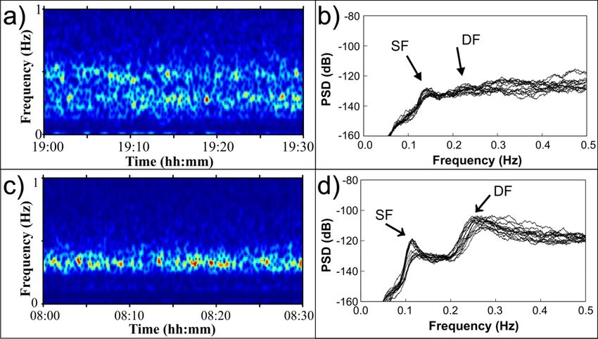
Geosciences 2019, 9, 115                                                                               2 of 14

eruption of the Axial Seamount, focusing on the magma recharge beneath the southeastern part of the
summit caldera [9,10], and the offshore earthquakes that are important for understanding Cascadia
interplate dynamics [11].
      In Europe, the European Multidisciplinary Seafloor and water column Observatory European
Research Infrastructure Consortium (EMSO-ERIC) aims to explore the seas around Europe to gain
a better understanding of geophysical, geochemical, and environmental phenomena [12]. The NEMO-SN1
multidisciplinary observatory, a node of EMSO ERIC, was deployed in the Western Ionian Sea first in
stand-alone configuration and then in cabled mode [13–15]. The NEMO-SN1 was deployed to monitor
the offshore seismicity linked to the seismogenic structures that cause the most destructive earthquakes
occurring in Italy [16], and to focus on the deep volcanic structures of Mt. Etna [16,17].
      Sea dynamics are the source of a typical background seismic signal: oceanographic noise. The origin
of this signal may be associated with different causes: the nonlinear interaction of the sea waves with
the seafloor bathymetry [18], local atmospheric conditions [19], wave height amplitudes caused by local
atmospheric perturbations [20,21], and resonance effects of sedimentary layers [22]. Waves and currents
generate seabed disturbances [23] and tides act as trigger of microearthquakes from normal faults [24].
Seismic data recorded by seafloor seismometers are affected by daily and seasonal variations, including
ocean loading, bottom currents, and marine organisms, as well as instrumental problems [23–30].
      A typical low-frequency seismic signal recorded at active volcano sites around the world is the volcanic
tremor, which is associated with the movement of magma, fluids, or gas [31]. Rising gas pockets within
the magma column interact with the conduit walls, causing a vibration that produces a tremor signal.
This vibration precedes and accompanies the explosive eruption; volcanic tremor plays a significant role
in real-time volcano monitoring as the pattern of this signal strongly reflects the evolution of the eruptive
activity [32–34]. In recent years, ocean bottom seismometers (OBSs) and seafloor observatories have been
used to monitor from the seafloor the volcanic activity of Stromboli [35] and Etna [36] volcanoes. In the case
of Mt. Etna, some authors reported that the south-eastern flank of this volcano slides into the Ionian Sea at
a rates of centimetres per year. These results are based on the data of seafloor displacement collected during
a 2016–2017 monitoring campaign [37].
      In this paper, we analyse the background seismic signal recorded by NEMO-SN1 to determine
the possible use of this signal in the volcano monitoring of Mt. Etna. Most amplitude increases of
the background seismic signal are related to oceanographic processes. In the Western Ionian Sea,
the influence of oceanographic dynamics on the background seismic signal is evident when comparing
seismic data and wave heights recorded at a buoy located off Catania city harbour [38]. Due to their
close correspondence, the gravity waves induced by local winds can be considered the main cause of
oceanographic noise generation.
      During the deployment of NEMO-SN1 seafloor observatory, a vigorous explosive event occurred
on Mt. Etna, generating the powerful 2002–2003 eruption. Analysing the background seismic signal
recorded by NEMO-SN1, we noted that some amplitude increases and frequencies are linked to
Mt. Etna’s activity, and that this signal has the same characteristics of the volcanic tremor recorded by
land seismometers. We performed continuous monitoring of the eruptive activity of Mt. Etna from the
seafloor, which is an unusual point of view. Some important evidence showed that the oceanographic
noise was recorded clearly when Mt. Etna explosive activity was absent. Instead, oceanographic
dynamics are hidden when explosive activity occurred (mainly as Strombolian explosions or lava
fountains). Recognizing that the volcanic and oceanographic dynamic processes coexist may help to
better comprehend the behaviour of Mt. Etna during its explosive activity, offering us the opportunity
to study the submerged flank of the Mt. Etna volcano and to monitor its volcanic activity.

2. The NEMO-SN1 Seafloor Observatory
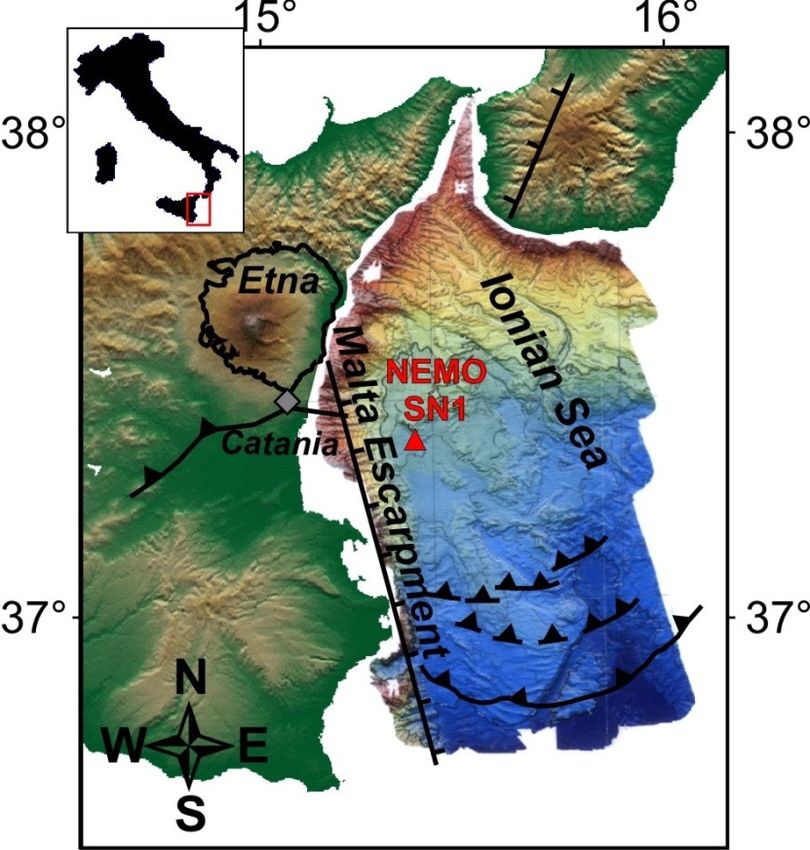
    The NEMO-SN1 seafloor observatory was deployed in the Western Ionian Sea, about 40 km from
Mt. Etna volcano, at a depth of 2100 m (Figure 1).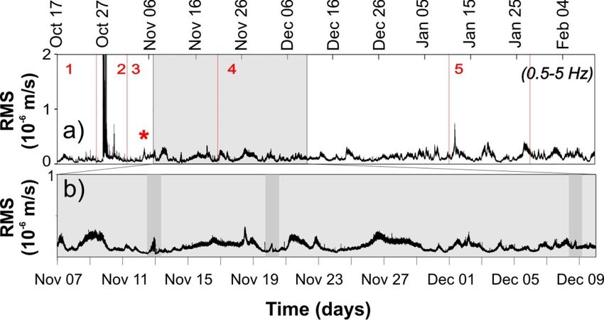
Geosciences 2019, 9, 115                                                                                              3 of 14
Geosciences 2018, 8, x FOR PEER REVIEW                                                                               3 of 15

                Western Ionian Sea multibeam
     Figure 1. Western                    multibeam map (redrawn
                                                            (redrawn from Marani et al. [39]). The The red
                                                                                                        red triangle
                                                                                                              triangle
     indicates the location of the NEMO-SN1 seafloor observatory. Simplified  Simplified geological
                                                                                          geological structures
                                                                                                      structures are
                                                                                                                   are
     also reported
     also reported (data
                    (data obtained
                           obtainedfrom fromprevious
                                               previousstudies
                                                        studies[39–41]),
                                                                [39–41]),where
                                                                          wherecontinuous
                                                                                  continuouslines with
                                                                                              lines withticks  refer
                                                                                                           ticks     to
                                                                                                                 refer
     extensional and   strike-slip   faults, and lines with black triangles are thrusts and reverse faults
     to extensional and strike-slip faults, and lines with black triangles are thrusts and reverse faults   (modified
     from Sgroifrom
     (modified   et al.Sgroi
                        [36]). et al. [36]).

     During the
     During  the first
                  first experiment,     NEMO-SN1 was
                        experiment, NEMO-SN1          was deployed
                                                            deployed in  in stand-alone
                                                                            stand-alone mode
                                                                                          mode and and operated
                                                                                                       operated
continuously with
continuously  with anan acoustic
                        acoustic link
                                  link for
                                        for over
                                            over 77 months
                                                    months (October
                                                             (October 2002-May
                                                                        2002-May 2003
                                                                                   2003 [15,16]).
                                                                                         [15,16]). We
                                                                                                    We analysed
                                                                                                       analysed
continuous  background     seismic  data  from  October  17,  2002 to February
continuous background seismic data from October 17, 2002 to February 10, 2003.   10, 2003.
     The seismic
     The seismic data
                  data were
                         were recorded
                               recorded by by aa 3-component
                                                 3-component broadband
                                                                broadband seismometer
                                                                              seismometer (Guralp
                                                                                              (GuralpCMG-1T,
                                                                                                       CMG-1T,
Guralp Systems
Guralp  Systems Ltd.-UK;
                 Ltd.-UK;0.0027
                             0.0027toto50
                                        50HzHzbandwidth
                                                bandwidthand and100
                                                                 100HzHz sampling
                                                                           samplingrate), and
                                                                                      rate), andsynchronized  by
                                                                                                   synchronized
a high-precision rubidium     clock  (drift~0.5   ms/day)   [13,42,43].  Seismological   recordings
by a high-precision rubidium clock (drift~0.5 ms/day) [13,42,43]. Seismological recordings were high  were high
quality due to
quality due to both
               both the
                     the installation
                         installation procedure
                                       procedure andand the
                                                        the good
                                                             good ground
                                                                   groundcoupling
                                                                             couplingofofthe
                                                                                          theseismometer
                                                                                               seismometer[44].
                                                                                                            [44].

3. The 2002-2003 Mt. Etna Eruption
3. The 2002-2003 Mt. Etna Eruption
     During the deployment of NEMO-SN1, a flank eruption occurred on Mt. Etna. The eruption
     During the deployment of NEMO-SN1, a flank eruption occurred on Mt. Etna. The eruption was
was characterized by moderate lava emission, intense explosive activity, and abundant ash emission.
characterized by moderate lava emission, intense explosive activity, and abundant ash emission. The
The eruption started on October 26, 2002, two hours after the occurrence of a seismic crisis [45,46],
eruption started on October 26, 2002, two hours after the occurrence of a seismic crisis [45,46], with
with fissures opening on the NE and S flanks [47]. NEMO-SN1, besides the recording the
fissures opening on the NE and S flanks [47]. NEMO-SN1, besides the recording the volcano-tectonic
volcano-tectonic earthquakes that preceded the onset of the eruption, recorded several dozens of
earthquakes that preceded the onset of the eruption, recorded several dozens of earthquakes
earthquakes associated with the seismic crisis, but these were not well recorded and located by the
associated with the seismic crisis, but these were not well recorded and located by the permanent
permanent seismic network on the volcano edifice [16].
seismic network on the volcano edifice [16].
     Magma accumulation, followed by ascent of magma and depressurization of the edifice due to
     Magma accumulation, followed by ascent of magma and depressurization of the edifice due to
the eastern flank spreading, triggered the eruption [47,48]. The eruption was associated with strong
the eastern flank spreading, triggered the eruption [47,48]. The eruption was associated with strong
ground deformation at different times and for different durations [49].
ground deformation at different times and for different durations [49].
     A concise description of the 2002–2003 Mt. Etna volcanic activity is reported in Table 1 (modified
     A concise description of the 2002–2003 Mt. Etna volcanic activity is reported in Table 1 (modified
from Andronico et al. [47] and Carbone et al. [50]).
from Andronico et al. [47] and Carbone et al. [50]).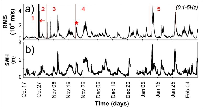
Geosciences 2018, 8, x FOR PEER REVIEW 4 of 15
Geosciences 2019, 9, 115 4 of 14
Table 1. Chronology of the volcanic activity during the 2002–2003 Mt. Etna eruption (modified from
previous studies [47,50]). Numbers 1 to 5 are the sub-periods of different volcanic activity compared
to the 1.
Table increases in background
Chronology seismic
of the volcanic signalduring
activity amplitudes shown inMt.
the 2002–2003 Figures
Etna2a and 3a.(modified from
eruption
previous studies
Period [47,50]). NumbersDate 1 to 5 are the sub-periods of different of
Chronology volcanic activityActivity
the Volcanic compared to
the increases in background seismic signal amplitudes shown in Figures 2a and 4a.
Degassing activity occasionally accompanied by ash
1 pre-eruption 15–25 October 2002
Period Date Chronology of emissions
the Volcanic Activity
At 20:12 UTC an intense earthquake swarm marks
Degassing activity occasionally accompanied by
1 pre-eruption 15–25 October 2002 the onset ofash theemissions
2002-2003 Etna eruption
26 October 2002
Strong Strombolian activity on the north-eastern
27 October 2002 At 20:12 UTC an intense earthquake swarm marks
2 eruption onset flank Etna eruption
28–3026October
October 2002
2002 the onset of the 2002-2003
27 October 2002 Intense
Strong Strombolian activity on theon
fire fountain activity the southern
north-eastern flankflank
2 eruption onset 31 October 2002
28–30 October 2002 Intense
End offirethefountain
effusiveactivity
activity onon thethe
southern
southernflankflank
31 October 2002 End of Persistence
the effusive activity on the southern
of the explosive flank
activity
Persistence of the explosive activity
Intense fire fountain activity on the southern flank
Eruption 1–11 November 2002 Intense fire fountain activity on the southern flank
Eruption 1–11 November 2002 Intermittent Strombolian activity
3 3
(explosive
(explosive
12–14 November 2002 Intermittent Strombolian activity
12–14 November 2002 Alternation of Strombolian activity and lava fountain
activity) 15–21 November 2002 Alternation of Strombolian activity and lava
activity) 15–21 November 2002
fountainepisode
episode
Effusive activity
Effusive activity
22 November
22 November 2002
2002
Middle-high
Middle-high explosive
explosive activity
activity
23–25
23–25 November
November 2002
2002
Eruption
Eruption Fountaining
Fountaining activity
activity
26–27 November 2002
4 (explosive and 26–27 November 2002 Strong jets and ash emission of explosive vent
4 (explosive and 28–30 November 2002 Strong jets and ash emission of explosive vent
effusive activity) 28–30 November 2002 Explosive activity on the southern flank
effusive activity) 1–10 December 2002 Explosive activity on the southern flank
1–10 December 2002 Effusive and explosive activity with variable
11–31 December 2002
Effusive and explosive
intensity on the activity
south-easternwithflank
variable intensity
11–31 December 2002
on the south-eastern
Progressive decrease of the frequencyflank and intensity
1–27 January 2003
5 end of eruption Progressive decrease of the
of explosive frequency and intensity
activity
1–2728 January2003
January 2003
Endofofexplosive
eruptive activity
5 end of eruption activity
28 January 2003
End of eruptive activity
4. Background Seismic Signals from NEMO-SN1
4. Background Seismic Signals from NEMO-SN1
We computed the RMS (Root Mean Square) amplitude of the seismic signal (Z component)
We computed
recorded by NEMO-SN1 the RMS (Root Meanthe
to discriminate Square) amplitude
contributions of sea
of the the dynamics
seismic signal (Z component)
and volcanic activity
recorded by NEMO-SN1 to discriminate the contributions of the sea dynamics and
of Mt. Etna. We reconstructed the time pattern of the background seismic signal filtering in two volcanic activity
of Mt. Etna.
frequency We reconstructed
bands: the first rangingthebetween
time pattern of5the
0.1 and Hz background seismic
(Figure 2a), and signal between
the second filtering 0.5
in two
and
5frequency
Hz (Figurebands: the signals
4a). The first ranging between
in these 0.1 and 5bands
two frequency Hz (Figure 2a), very
appeared and the second between
differently. Figure 2a0.5 and
shows
5 Hz
the (Figure
signal 3a). The
filtered signals
in 0.1–5 in these
Hz and showstwo frequency
several bands appeared
background increases very
with differently.
high amplitudesFigurethat
2a
shows several
lasted the signal filtered in 0.1–5 Hz and shows several background increases with high amplitudes
days.
that lasted several days.
Comparison between
Figure 2. Comparison between(a)(a)RMS
RMSofofbackground
backgroundseismic
seismicsignal
signal(filtered
(filteredininthe
therange
range ofof
0.10.1
toto
5
5Hz)
Hz)and
and(b)
(b)significant
significantSea
SeaWave
WaveHeight
Height(SWH).
(SWH).Red
Redvertical
verticalbars
barsand
andnumbers
numbersreferrefer to
to the
the period
period of of
volcanic activity described
described in Table 1; the red arrow indicates the 2002–2003
2002–2003 eruption
eruption onset;
onset; the
the red
red
asterisk
asterisk marks
marks thethe episode
episode of
of oceanographic
oceanographic noise
noise increase
increase analysed
analysed in
in Figure
Figure 3b.
4b.Geosciences 2019, 9, 115 5 of 14
Geosciences 2018, 8, x FOR PEER REVIEW 6 of 15
3. (a) 4.
FigureFigure Vertical component
(a) Vertical component of of
background
background seismic signal(from
seismic signal (from November
November 4, 2002,
4, 2002, 12:0012:00
p.m. top.m. to
NovemberNovember 5, 12:00 p.m.). The amplitude increase was recorded during a lava fountain episode. DueDue to
5, 12:00 p.m.). The amplitude increase was recorded during a lava fountain episode.
the close correspondence
to the between
close correspondence the background
between seismic
the background signalsignal
seismic and the
andvolcanic activity,
the volcanic we indicated
activity, we
indicated
this signal as a this signaltremor.
volcanic as a volcanic tremor. (b)
(b) Vertical Vertical component
component of background
of background seismicseismic
signal signal
(from(from
November
November
21, 12:00 a.m. to 21, 12:00 a.m.23,
November to12:00
November
a.m.).23, 12:00
This a.m.). This seismic
background background seismic
increase wasincrease was not with
not associated
associated with volcanic activity, so we labelled this signal oceanographic noise.
volcanic activity,
Geosciences 2018, 8, xso wePEER
FOR labelled
REVIEW this signal oceanographic noise. 5 of 15
The amplitude trends of both signals are rather similar (Figures 4a,b), except for the roughly
higher values of oceanographic noise amplitude.
In order to estimate the quantitative relationship between SWH and RMS computed in both the
0.1–5 Hz and the 0.5–5 Hz frequency band, we performed a cross-correlation analysis between the
two signals. We considered the two episodes represented in Figure 4 as well as the whole period
shown in Figures 2a,b (Figure 5).
FigureFigure
4. (a) 3.
RMS(a) RMS computed
computed on on
thethe background seismic
background seismic signal
signalfiltered within
filtered 0.5–5
within Hz. Vertical
0.5–5 bars bars
Hz. Vertical
and numbers refer to the period of volcanic activity described in Table 1. The light
and numbers refer to the period of volcanic activity described in Table 1. The light grey rectangular grey rectangular
area marks the time series zoomed in Figure 3b; the red asterisk represents the background signal
area marks the time series zoomed in Figure 4b; the red asterisk represents the background signal
increases associated with the volcanic tremor shown in Figure 4a. (b) Time series zoomed in the
increases associated with the volcanic tremor shown in Figure 3a. (b) Time series zoomed in the period
period of November 7 to December 10, 2002. Three increases of tremor amplitude (highlighted with
of November 7 tooccurred
grey stripes) December 10, two
during 2002.
lavaThree increases
fountains and theof tremorofamplitude
opening new effusive(highlighted
vents [47,50]. with grey
stripes) occurred during two lava fountains and the opening of new effusive vents [47,50].
These increases were not correlated with the explosive activity of Mt. Etna but were related to
These
the seaincreases
dynamics. were not 2b
Figure correlated
shows the with
Seathe
Wave explosive activityrecorded
Height (SWH) of Mt. Etnaat thebut
buoywere related
located off to the
sea dynamics. Figure [38].
Catania harbour 2b shows the Seabetween
A correlation Wave Height (SWH)ofrecorded
the occurrence these noise at increases
the buoyassociated
located off Catania
with
harbourSWH[38].data is observed. between
A correlation This highlights that the noise
the occurrence is mainly
of these noiseassociated
increaseswith the localwith
associated sea wave
SWH data
conditions
is observed. Thisaffecting the seismological
highlights that the noise signal
is in the microseismic
mainly associatedband with(0.1 –0.5local
the Hz; [25]).
sea wave conditions
In Figure 3a, we reconstructed the time pattern of the background seismic signal filtered in the
affecting the seismological signal in the microseismic band (0.1–0.5 Hz; [25]).
frequency range between 0.5 and 5 Hz, as tremors mainly reflect the volcanic activity in this range
In Figure 4a, we reconstructed the time pattern of the background seismic signal filtered in the
[31]. The correspondence between the beginning and evolution of the explosive activity and the
frequency range
pattern between
of the 0.5 and
background 5 Hz,signal
seismic as tremors
recorded mainly reflect the (Figure
by NEMO-SN1 volcanic 3a)activity in thisusing
was checked range [31].
The correspondence
reports describing between the activity
the volcanic beginning [51]. and evolution of the explosive activity and the pattern
of the background
The increasesseismic signal recorded
in background signal areby NEMO-SN1
strongly linked to(Figure 4a) was
the explosive checked
activity usingthe
of Mt. Etna: reports
highest amplitudes were
describing the volcanic activity [51]. visible during the eruption onset (27 October 2002), whereas slight
amplitude increases were only visible during the occurrence of lava fountains and fracture opening
episodes, corresponding to the main phases of volcanic activity (Table 1). These increases in the
background signal showed evident similarities with the low-frequency signal identified as volcanic
tremor, typically observed on land; in the time period of November 7 to December 9 (Figure 3b), two
lava fountain episodes and the opening of new effusive vents occurred, accompanied by effusive and
Strombolian activity [47,50].Geosciences 2019, 9, 115 6 of 14
The increases in background signal are strongly linked to the explosive activity of Mt. Etna:
the highest amplitudes were visible during the eruption onset (27 October 2002), whereas slight
amplitude increases were only visible during the occurrence of lava fountains and fracture opening
episodes, corresponding to the main phases of volcanic activity (Table 1). These increases in the
background signal showed evident similarities with the low-frequency signal identified as volcanic
tremor, typically observed on land; in the time period of November 7 to December 9 (Figure 4b),
two lava fountain episodes and the opening of new effusive vents occurred, accompanied by effusive
and Strombolian activity [47,50].
5. Time, Spectral, and Polarization Analyses
Time, spectral, polarization, and particle-motion analyses were performed on continuous seismic
signals to characterize volcanic tremors and oceanographic noise. In particular, we compared
two episodes of continuous signal amplitude increase to discriminate between the source of the
two signals. The continuous Z-component signals shown in Figure 3a,b were 0.1–5 Hz filtered.
A background signal increase was recorded simultaneously with the occurrence of a lava fountain
episode (4–5 November 2002; Figure 3a). Other increases in the background seismic signal were not
associated with explosive activity. One of these episodes (Figure 3b) occurred on 21–22 November 2002.
The amplitude trends of both signals are rather similar (Figure 3a,b), except for the roughly higher
values of oceanographic noise amplitude.
In order to estimate the quantitative relationship between SWH and RMS computed in both the
0.1–5 Hz and the 0.5–5 Hz frequency band, we performed a cross-correlation analysis between the two
signals. We considered the two episodes represented in Figure 3 as well as the whole period shown
in Figure 2a,b (Figure
Geosciences 5).
2018, 8, x FOR PEER REVIEW 7 of 15
Figure 5. Cross-correlation computed
Figure 5. Cross-correlation between
computed betweenthetheRMS
RMS 0.1–5 Hzfiltered
0.1–5 Hz filtered
andand
SWHSWH
(black(black line) and the
line) and
the RMS
RMS 0.5–5 Hz 0.5–5 and
filtered Hz filtered
SWHand SWHline)
(grey (greyon
line) onvolcanic
(a) (a) volcanictremor
tremor (November
(November 4–5, 4–5,
2002 in Figure
2002 in Figure 3a),
4a), (b) oceanographic noise (November 21–22 in Figure 4b) and (c) the whole period (November 1,
(b) oceanographic noise (November 21–22 in Figure 3b) and (c) the whole period (November 1,
2002–February 10, 2003). The cc values in the rectangular area represent the correlation coefficient.
2002–February 10,are
The lags 2003). The
negative cc seismic
when valuesRMSin the rectangular
follows area represent the correlation coefficient.
SWH time series.
The lags are negative when seismic RMS follows SWH time series.
The results show that the correlation between volcanic tremor and SWH is very poor, in
particular for the seismic signal filtered in the 0.1–5 Hz frequency band [25] (cc = 0.37; Figure 5a). On
the other hand, a very high correlation between oceanographic noise and SWH is found (correlation
coefficients cc = 0.97 and cc = 0.73 for 0.1–5 Hz and 0.5–5 Hz, respectively; see Figure 5b). Such findings
suggest that the oceanographic noise recorded by NEMO-SN1 is probably due to gravity waves
generated on the air-sea interface.
With the aim of supporting these results, a cross-correlation analysis was performed on theGeosciences 2019, 9, 115 7 of 14
The results show that the correlation between volcanic tremor and SWH is very poor, in particular
for the seismic signal filtered in the 0.1–5 Hz frequency band [25] (cc = 0.37; Figure 5a). On the other
hand, a very high correlation between oceanographic noise and SWH is found (correlation coefficients
cc = 0.97 and cc = 0.73 for 0.1–5 Hz and 0.5–5 Hz, respectively; see Figure 5b). Such findings suggest
that the oceanographic noise recorded by NEMO-SN1 is probably due to gravity waves generated on the
air-sea interface.
With the aim of supporting these results, a cross-correlation analysis was performed on the whole
period (Figure 5c). We started the cross-correlation analysis on November 1, 2002, excluding the peak
linked to the seismic swarm that preceded and accompanied the eruption onset. The cross-correlation
confirms a higher value for the RMS computed in the 0.1–5 Hz band (cc = 0.74) compared to the
one in the 0.5–5 Hz band (cc = 0.57). This indicates that the seismic signal recorded by NEMO-SN1
mainly consists of oceanographic noise, well detected in the 0.1–0.5 Hz frequency band [25]. Further,
the results suggest that the local wind could be the main source in oceanographic noise generation.
The spectrogram and spectra (Figure 6a,c and Figure 6b,d, respectively) computed on the two
signals are different mainly in the 0.01–0.5 Hz frequency band. To better appreciate the spectral
difference between volcanic tremor and oceanographic noise, we compared spectrograms computed
on the two signals related to the lava fountain episode and a background signal increase (Figure 6a,c),
both calculated in a 30-minute time window (grey striped in Figure 3a,b). We observed that the
volcanic tremor (Figure
Geosciences 2018, 8, 6a)
x FORwas
PEERcharacterized
REVIEW by a variable spectral amplitude content 8inof the 15 0.1–0.5 Hz
frequency band,
tremorwhereas
(Figure 6a)oceanographic
was characterizednoise (Figurespectral
by a variable 6c) had one well-defined
amplitude content in thenear-monochromatic
0.1–0.5 Hz
frequency around
frequency0.3 Hz.whereas oceanographic noise (Figure 6c) had one well-defined near-monochromatic
band,
frequency around 0.3 Hz.
Figure 6. (a)Figure
Spectrogram for a 30-minute
6. (a) Spectrogram for a 30-minute time
timewindow (vertical
window (vertical grey grey
stripe stripe
in Figurein4a)
Figure 3a) for volcanic
for volcanic
tremor recorded
tremor recorded between between
7:00 7:00
andand 7:30p.m.
7:30 p.m. GMTGMT during a lava a
during fountain episode. Red,
lava fountain yellow, andRed, yellow,
episode.
green colours define the dominant spectral amplitudes; light to dark blue colours define lower
and green colours define the dominant spectral amplitudes; light to dark blue colours define lower
amplitudes and background. The spectrogram shows a variable low-frequency content in the 0.1–1
amplitudes Hzandfrequency
background. The
band. (b) spectrogram
Power shows
Spectral Density a variable
(PSD) computedlow-frequency
for 14 30-minutecontent
segmentsin (Zthe 0.1–1 Hz
component of the seismometer), zoomed in on the frequency band 0–0.5
frequency band. (b) Power Spectral Density (PSD) computed for 14 30-minute segments (Z component Hz. Single Frequency (SF)
and Double Frequency (DF) peaks are not evident. (c) Spectrogram for a 30-minute time window
of the seismometer), zoomed in on the frequency band 0–0.5 Hz. Single Frequency (SF) and Double
(vertical grey stripe in Figure 4b) for oceanographic noise recorded between 8:00 and 8:30 a.m. GMT.
Frequency (DF) peaks are not evident.
A near-monochromatic frequency(c) Spectrogram
around for ait30-minute
0.3 Hz is visible; is consistent time window
with the DF peak.(vertical
(d) PSD grey stripe
in Figure 3b)computed
for oceanographic
on 14 30-minute noise recorded
segments between
(Z component 8:00
of the and 8:30 a.m.
seismometer), zoomedGMT.
in on A
thenear-monochromatic
frequency
band 0–0.5
frequency around 0.3Hz.HzThe two frequency
is visible; peaks relatedwith
it is consistent to microseisms
the DF peak.(~0.1 and
(d)~0.3
PSDHz)computed
are visible. on 14 30-minute
segments (ZA component
more detailedof the seismometer),
spectral analysis of bothzoomed
oceanographicin onnoisethe frequency
and volcanicbandtremor0–0.5 Hz.
signals wasThe two
frequency peaks related
performed on the 0.0 to–0.5
microseisms
Hz frequency (~0.1
bandand ~0.36b,d)
(Figures Hz) onare14visible.
30-minute segments. The volcanic
tremor showed a rough frequency peak close to 0.1 Hz, whereas spectral amplitudes remained
A morealmost
detailed spectral
constant analysis
at frequencies of both
ranging oceanographic
between noise and
0.2 and 0.5 Hz (Figure volcanic
6b). Spectra tremor
computed on signals was
oceanographic noise (Figure 6d) show the two peaks at frequencies close to 0.1 and 0.3 Hz. These
performed on the 0.0–0.5 Hz frequency band (Figure 6b,d) on 14 30-minute segments. The volcanic tremor
frequencies correspond to the two typical microseismic peaks caused by ocean wave energy coupling
showed a rough frequency
into the peak
motion of the close
earth: to 0.1Frequency
the Single Hz, whereas spectral
(SF) peak (∼0.1 Hz)amplitudes
and the muchremained almost constant
stronger Double
at frequencies ranging
Frequency between
(DF) 0.2Hz)
peak (∼0.3 and[25].
0.5TheHzSF(Figure
peak is6b). Spectra
generated computed
by direct on oceanographic
ocean wave pressure noise
fluctuations
(Figure 6d) show at thepeaks
the two ocean at
bottom; the amplitude
frequencies closeoftowave-induced
0.1 and 0.3pressure fluctuations
Hz. These decreases
frequencies correspond to
exponentially with depth from the sea surface depending on the bathymetry. The DF peak is
produced by the interaction of sea gravity waves with the seafloor [19,25]. The SF peak has been
associated with high-amplitude storm waves impacting long stretches of coastline nearly
simultaneously, whereas the DF peak is related to wind speed and direction, implying that the
energy reaching the ocean floor is generated locally by ocean gravity waves [52]. In the Ionian Sea,
the SF peak is considered characteristic of deep-sea monitoring sites that are not too far from the
coastlines, which is more easily observed during favourable weather conditions. The presence of theGeosciences 2019, 9, 115 8 of 14
the two typical microseismic peaks caused by ocean wave energy coupling into the motion of the earth:
the Single Frequency (SF) peak (~0.1 Hz) and the much stronger Double Frequency (DF) peak (~0.3 Hz) [25].
The SF peak is generated by direct ocean wave pressure fluctuations at the ocean bottom; the amplitude of
wave-induced pressure fluctuations decreases exponentially with depth from the sea surface depending on
the bathymetry. The DF peak is produced by the interaction of sea gravity waves with the seafloor [19,25].
The SF peak has been associated with high-amplitude storm waves impacting long stretches of coastline
nearly simultaneously, whereas the DF peak is related to wind speed and direction, implying that the
energy reaching the ocean floor is generated locally by ocean gravity waves [52]. In the Ionian Sea, the
SF peak is considered characteristic of deep-sea monitoring sites that are not too far from the coastlines,
which is more easily observed during favourable weather conditions. The presence of the energetic DF peak
suggests the influence of local winds [53]. Although spectra of oceanographic noise showed well-defined
SF and DF peaks (Figure 6d), in the volcanic tremor signal spectra, the SF peaks are not clearly delineated
(Figure 6b). The spectral amplitudes of SF and DF peaks computed for the volcanic tremor signal were
both about −130 dB, whereas the SF and DF peaks of oceanographic noise signal had more pronounced
spectral amplitudes (about −120 dB and −90 dB, respectively). This means that spectral amplitudes linked
Geosciences 2018, 8, x FOR PEER REVIEW 9 of 15
to volcanic activity hide the effects linked to the sea in this low-frequency band.
Due to the availability
respectively). This means thatof continuous broadband
spectral amplitudes linked tothree-component
volcanic activity hidesignals, we
the effects performed
linked
to the and
polarization sea inparticle-motion
this low-frequency band. with the aim of identifying the direction of the locations of
analyses
the sources.DueWe usedto thethe availability
standardofcovariance
continuousmatrix
broadband three-component
method [54,55], which signals,
works weinperformed
the time domain
polarization and particle-motion analyses with the aim of identifying the direction of the locations of
by bandpass filtering the signal around the frequency band of interest. The broadband data from the
the sources. We used the standard covariance matrix method [54,55], which works in the time domain
different
bycomponents
bandpass filtering weretheconverted to ground
signal around velocity
the frequency band by deconvolving
of interest. the instrument
The broadband data from the response.
We computed
differentthe polarization
components on the three-component
were converted to ground velocity bysignals by applying
deconvolving the Covariance
the instrument response. Matrix
Decomposition
We computed (CMD) the developed
polarization in
on the SEISMPOL code
the three-component [56]. by applying the Covariance Matrix
signals
Decomposition (CMD) developed in the SEISMPOL code [56].
Figure 7. Polarization
Figure and particle
7. Polarization motion
and particle computed
motion on amplitude
computed on amplitudeincreases
increasesassociated
associatedwith:
with:(a)
(a)volcanic
volcanic
tremor and tremor and (b) noise.
(b) oceanographic oceanographic
Examples noise. Examples of rectilinearity,
of rectilinearity, incidence, and incidence,
azimuthandvalues
azimuth
computed
values computed on a 10-s-long window of 0.1–2 Hz-filtered signal; hodograms of particle motion
on a 10-s-long window of 0.1–2 Hz-filtered signal; hodograms of particle motion were computed on
were computed on a 4-s-long window. A total of 110 windows for both volcanic tremor and
a 4-s-long window. A total of 110 windows for both volcanic tremor and oceanographic noise were
oceanographic noise were analysed. Polarization and particle motion show high values of
analysed. Polarization
rectilinearity and
(> 0.8) particle
and motion angles
high incidence show (> high
60°),values
typicalof rectilinearity
converted phases(> 0.8)P-waves
from and high incidence
to S-
angles (> 60 ◦ ), typical converted phases from P-waves to S-waves (P-to-S) at the seafloor boundary in both
waves (P-to-S) at the seafloor boundary in both signals. The azimuth values reported in the two rose
signals. diagram
The azimuth values
show that the reported in the propagated
volcanic tremor two rose diagram
from NWshow to SE,that the volcanic
compatible with atremor propagated
wave front
coming from Mt. Etna; oceanographic noise shows a constant E–W direction roughly
from NW to SE, compatible with a wave front coming from Mt. Etna; oceanographic noise shows a constant perpendicular
to the coast
E–W direction and consistent
roughly with the
perpendicular sea wave
to the coast direction of propagation.
and consistent with the sea wave direction of propagation.
The background seismic signal recorded by NEMO-SN1 has a complex waveform, where
different aspects act concurrently with the polarization of a signal in the same frequency band. We
attempted polarization analyses using a total of 110 10-s-long windows of 0.1–2 Hz-filtered signal.
The results from polarization were compared with those derived from particle motion analysis,
performed using 110 4-s-long windows of 0.1–2 Hz filtered signal. Polarization and particle motion
computed on volcanic tremor and oceanographic noise showed high values of rectilinearity (>0.8)Geosciences 2019, 9, 115 9 of 14
The background seismic signal recorded by NEMO-SN1 has a complex waveform, where different
aspects act concurrently with the polarization of a signal in the same frequency band. We attempted
polarization analyses using a total of 110 10-s-long windows of 0.1–2 Hz-filtered signal. The results from
polarization were compared with those derived from particle motion analysis, performed using 110 4-s-long
windows of 0.1–2 Hz filtered signal. Polarization and particle motion computed on volcanic tremor and
oceanographic noise showed high values of rectilinearity (>0.8) and high incidence angles (>60◦ ) (Figure 7b).
Results from these analyses indicate that most energy in the 0.1–2 Hz frequency band is due to the generation
of converted waves prevalently from P–waves to S–waves (P-to-SV) at the seafloor boundary for both signals.
Our results concur with those of Imanishi et al. [57], who found that low-frequency noise is composed of
nearly vertical incident S-waves. In the case of volcanic tremors, our results agree with those recorded at
Mt. Etna and other volcanic areas. A wavefield consisting of P-waves radiated by a vertical extended source
was observed at Mt. Etna [58,59]; body waves radiated by an extended source characterized the wavefield
Geosciences 2018, 8, x FOR PEER REVIEW 10 of 15
recorded some kilometres away from the summit craters. Dominant P-SV converted waves have been
identified in the Phlegrean
observed at Mt. EtnaCaldera [60],waves
[58,59]; body whereas S-waves
radiated were identified
by an extended as the dominant
source characterized the wavefieldwave type at
Arenal volcano
recorded[61].
some kilometres away from the summit craters. Dominant P-SV converted waves have been
identified
The most in the difference
relevant Phlegrean Caldera
between[60], whereas
volcanicS-waves
tremor were
andidentified as the dominant
oceanographic noisewave type
is observed in the
at Arenal volcano [61].
strong directivity of wave propagation, shown in the two rose diagrams in Figure
The most relevant difference between volcanic tremor and oceanographic noise is observed in
7a,b. Volcanic tremor
propagatesthe from
strongNW to SE, of
directivity compatible with ashown
wave propagation, waveinfront coming
the two from Mt.
rose diagrams Etna,7a,b.
in Figures with azimuth values
Volcanic
tremor ◦propagates ◦
ranging from 290 to 320 (Figure 7a). The particle motion of oceanographic noise (Figure 7b) with
from NW to SE, compatible with a wave front coming from Mt. Etna, shows an E–W
azimuth values ranging
direction, corresponding fromwave
to the sea 290° to 320° (Figure
direction 7a). The particle
perpendicular motion
to the coastof (azimuth
oceanographic noise 85–94◦ ).
ranging
(Figure 7b) shows an E–W direction, corresponding to the sea wave direction perpendicular to the
coast (azimuth ranging 85–94°).
6. Comparison between Volcanic Tremor and Oceanographic Noise
6. Comparison between Volcanic Tremor and Oceanographic Noise
We computed the Power Spectral Density (PSD) by applying Fast Fourier Transform to characterize
the backgroundWe computed
seismic the Figure
signal. Power 8a–d
Spectral
showDensity (PSD)computed
the PSD by applying Fast
over Fourier Transform
two-hour-long to
segments chosen
characterize the background seismic signal. Figures 8a–d show the PSD computed over two-hour-
in four different periods: (1) October 17 refers to the non-eruptive period preceding the eruption onset,
long segments chosen in four different periods: (1) October 17 refers to the non-eruptive period
(2) Octoberpreceding
27 coincides with the
the eruption eruption
onset, onset,
(2) October 27 (3) November
coincides with the22eruption
corresponds to November
onset, (3) a background
22 seismic
increase not associatedtowith
corresponds explosiveseismic
a background activity,increase
and (4)not
December
associated8 with
is theexplosive
eruptiveactivity,
period.and (4)
December 8 is the eruptive period.
Figure 8. Two-hour-long PSD computed
Figure 8. Two-hour-long PSD computed on seismic data.
on seismic data.Four differentintervals
Four different intervalswere were analysed:
analysed: (a) (a) non-
non-eruptive
eruptive period (Octoberperiod (October
17, 2002), (b)17,the
2002), (b) theonset
eruption eruption onset (October
(October 27, (c)
27, 2002), 2002), (c) background
background signal increase
signal increase not correlated with volcanic activity (November 22, 2002), and (d) the eruptive period
not correlated with volcanic activity (November 22, 2002), and (d) the eruptive period (December 8, 2002).
(December 8, 2002). The two black lines represent the Peterson's reference models [62]. (b) Seismic
The two black lines represent the Peterson’s reference models [62]. (b) Seismic data show the maximum
data show the maximum energy content in correspondence of the eruption onset, where the spectral
energy content in correspondence
amplitudes of themodel.
exceed the reference eruption onset, where
(d) Spectrum the on
computed spectral amplitudes
the eruptive period isexceed
similar the
in reference
model. (d)frequency
Spectrum to computed
the previouson the but
period eruptive
shows period is similar
lower energy. Theirin frequency
patterns to the previous
are representative of theperiod but
shows lowervolcanic activity.
energy. Their (a)patterns
The non-eruptive period and (c)of
are representative thethe
background
volcanicsignal increase
activity. shownon-eruptive
(a) The a different period
trend with two microseismic spectral peaks at ~0.1 and ~0.3 Hz, respectively (indicated with black
and (c) thearrows),
background signal increase show a different trend with two microseismic spectral peaks at ~0.1
associated with sea dynamics.
and ~0.3 Hz, respectively (indicated with black arrows), associated with sea dynamics.
The comparison of the computed spectra with the reference Low-Noise Model (LNM) and High-
Noise Model (HNM) curves [62] shows that during the eruption onset (Figure 8b), the spectral
amplitude exceeded the HNM curves, being about 40 dB higher than the PSD computed in the
eruptive period (Figure 8d). Both spectra show that the energy of the seismic data is concentrated in
the 0.1–4 Hz frequency band, with a higher energy content in the 0.5–2 Hz frequency band (Figure
8b), which was typical of the Mt. Etna volcanic tremor during the occurrence of the 13 lava fountains
in 2013 [36]. The non-eruptive period (Figure 8a) and the background seismic increase period (FigureGeosciences 2019, 9, 115 10 of 14
The comparison of the computed spectra with the reference Low-Noise Model (LNM) and
High-Noise Model (HNM) curves [62] shows that during the eruption onset (Figure 8b), the spectral
amplitude exceeded the HNM curves, being about 40 dB higher than the PSD computed in the eruptive
period (Figure 8d). Both spectra show that the energy of the seismic data is concentrated in the 0.1–4
Hz frequency band, with a higher energy content in the 0.5–2 Hz frequency band (Figure 8b), which
was typical of the Mt. Etna volcanic tremor during the occurrence of the 13 lava fountains in 2013 [36].
The non-eruptive period (Figure 8a) and the background seismic increase period (Figure 8c) show
a different pattern, with the presence of two peaks in the typical microseismic band: the SF peak
(~0.1 Hz) and the stronger DF peak (~0.3 Hz) [25]. In Figure 8a,c, the pattern of microseismic spectra
in the 0.01-0.5 Hz band shows the typical spectral features of deep water, as in the Cascadian area [26].
7. Discussion and Conclusions
The typical background seismic signal recorded by seafloor stations is a continuous oceanographic
noise that is associated with tidal variation and currents and is due to ocean loading, which causes local
crustal stresses [27]. In order to focus on the possible generation of oceanographic noise in the Ionian
Sea, we computed the RMS amplitude pattern of the seismic signal filtered in the frequency range
between 0.1 and 5 Hz, and compared it with the wave height recorded at the buoy located off Catania
harbour [38] (Figure 2b). The frequency of oceanographic noise recorded by NEMO-SN1 is primarily
below 0.5 Hz and we found two distinctive peaks at ~0.1 and ~0.3 Hz (SF and DF microseismic peaks,
respectively) in the spectrum of the oceanographic noise signal (Figure 6d). The sea gravity waves
induced by local winds are the main cause of the oceanographic noise generation.
In October 2002, a vigorous eruptive and explosive event started on Mt. Etna. The eruption
provided an occasion to test the capacity of NEMO-SN1 to record the low-frequency seismic signals
associated with volcanic activity (volcanic tremor) and to discriminate the low-frequency signals
from those associated with sea dynamics (oceanographic noise). During the eruption, we observed
a strict correspondence between amplitude increases of the background seismic signal recorded at
NEMO-SN1 and the occurrence of explosive activity (Figures 4 and 3a). Spectral analysis performed
on the background seismic signal demonstrated a frequency range between 0.1 and 4 Hz, with higher
energy in the 0.5-2 Hz frequency band (Figure 8b), which is comparable to the predominant frequencies
closer to 2 Hz recorded by land stations located on Mt. Etna [34,63] and by ocean bottom seismometers
(OBSs) located close to Etna and Stromboli volcanoes [35,36]. Changes in spectral amplitudes during
the two different phases of the eruption (from about –60 dB to –120 dB in Figure 8b,d) depend on the
intensity of volcanic activity [34], but also on the tremor source position [63].
The cross-correlation analysis between the seismic signal (RMS) recorded by NEMO-SN1 and
the SWH suggests that the oceanographic noise probably originated from local winds perturbing the
sea surface. Such noise dominates the seismic signal over the whole studied period and it is mainly
concentrated in the 0.1-5 Hz frequency band [25]. On the other hand, the seismic signal generated
by the volcano (volcanic tremor) highlights a very low correlation with the SWH and, accordingly,
with the oceanographic noise. Consequently, the cross-correlation analysis between RMS and SWH
allowed us to effectively discriminate the volcanic tremor from the oceanographic noise.
The wave field compositions resulting from polarization and particle motion analyses computed
for volcanic tremor and oceanographic noise are rather similar, showing a complex overlapping
pattern that consists mainly of converted waves (mainly P to SV waves). A source mechanism linked
to pressure variations due to fluid movements is the driving force for both volcanic tremor and
oceanographic noise generation. In the case of volcanic tremor, this mechanism is compatible with
the presence of a storage zone for Mt. Etna that extends under the seafloor, linked to the dynamics of
the magmatic fluids [64–68]. A compressive mechanism linked to pressure variations may explain the
wave field composition of oceanographic noise. We inferred that oceanographic noise is largely due to
the pressure applied by the sea gravity waves on the seafloor, which deform the underlying sediment
and crust.Geosciences 2019, 9, 115 11 of 14
The most important difference between volcanic tremor and oceanographic noise is the strong
directivity of the two signals. Volcanic tremors show a preferential direction from NW to SE
(Figure 7a). This confirms that the 0.5–2 Hz bandpass filtered signals come directly from Mt. Etna.
The oceanographic noise shows a marked directivity from polarization and particle motion analyses,
having a predominant wave direction from E to W (rose diagram with a narrow range of azimuth
values ranging from 85◦ to 94◦ in Figure 7b) and corresponding to the sea wave direction roughly
perpendicular to the coast.
The spectra computed on volcanic signals recorded during the occurrence of explosive activity
of Mt. Etna and non-eruptive periods provide meaningful results. Seismic data show the maximum
energy corresponding to the eruption onset and eruptive period when their patterns are representative
of the volcanic activity. During the non-eruptive period, increases in background signal are observed
but spectra have a different trend with two visible microseismic spectral peaks at ~0.1 and ~0.3 Hz
(Figure 8a,c, respectively) associated with the sea dynamics.
In the absence of explosive activity at Mt. Etna, sea dynamics prevail. When explosive activity
increases, the energy associated with the volcanic tremor linked to Mt. Etna volcanism becomes the
main contribution, prevailing on the oceanographic dynamics. Since volcanic tremors, as recorded by
land seismic stations around Mt. Etna, were also observed on the seafloor, we inferred that explosive
activity is generated by processes that are efficiently detected by the seafloor station.
The monitoring of the volcanic activity from a seafloor observatory can help to pinpoint possible
hazard sources in the Western Ionian Sea. Understanding the similarities and differences of seismic
signals containing the contribution of both volcanic and oceanographic processes may help assessing
the behaviour during explosive activity at Mt. Etna, which is crucial to minimizing volcanic hazards.
Author Contributions: P.F. conceived and designed the field experiments; T.S. and G.D.G. analysed the data
and contributed to the interpretation of the results; T.S. contributed to the writing of the manuscript and figure
preparation. All authors participated in discussions of the results.
Funding: This research was funded by European Commission grant number 283465.
Acknowledgments: The authors thank Hitoshi Mikada and Valerio Iafolla for their valuable comments. We are
indebted to the Assistant Editor Richard Li and the two anonymous reviewers for the fruitful revision of the paper
and suggestions.
Conflicts of Interest: The authors declare no conflict of interest.
References
1. Favali, P.; Person, R.; Barnes, C.R.; Kaneda, Y.; Delaney, J.R.; Hsu, S.-K. Seafloor Observatory Science.
In Proceedings of the OceanObs’09: Sustained Ocean Observations and Information for Society conference
2.2010, Venice, Italy, 21–25 September 2009; Hall, J., Harrison, D.E., Stammer, D., Eds.; ESA Publication:
Venice, Italy, 2010. WPP-306.
2. Favali, P.; Beranzoli, L.; De Santis, A. (Eds.) Seafloor Observatories: A New Vision of the Earth from the
Abyss. Springer-Praxis Books in Geophysical Sciences; Springer: Berlin/Heidelberg, Germany, 2015; 676p,
ISBN 978-3-642-11373-4. e-ISBN 978-3-642-11374-1. [CrossRef]
3. Butler, R.; Chave, A.D.; Duennebier, F.K.; Yoerger, D.R.; Petitt, R.; Harris, D.; Wooding, F.B.; Bowen, A.D.;
Bailey, J.; Jolly, J.; et al. Hawaii-2 Observatory pioneers opportunities for remote instrumentation in ocean
studies. Eos Trans. AGU 2000, 81, 161–163. [CrossRef]
4. Caplan-Auerbach, J.; Duennebier, F.K. Seismic and acoustic signals detected at Lo’ihi Seamount by the
Hawaii Undersea Geo-Observatory. Geochem. Geophys. Geosys. 2001, 2. [CrossRef]
5. ONC-Ocean Networks Canada. Available online: www.oceannetworks.ca (accessed on 20 December 2018).
6. Fox, C.G.; Dziak, R.P.; Matsumoto, H.; Schreiner, A.E. Potential for monitoring low level seismicity on the
Juan de Fuca Ridge using military hydrophone arrays. Mar. Technol. Soc. J. 1994, 27, 22–30.
7. Dziak, R.P.; Hammond, S.R.; Fox, C.G. A 20-year hydroacoustic time series of seismic and volcanic events in
the Northeast Pacific Ocean. Oceanography 2011, 24, 280–293. [CrossRef]Geosciences 2019, 9, 115 12 of 14
8. OOI-Ocean Observatories Initiative. Available online: https://oceanobservatories.org/ (accessed on
18 September 2018).
9. Tolstoy, M.; Wilcock, W.S.D.; Tan, Y.J.; Waldhauser, F. A tale of two eruptions: How data from Axial Seamount
led to a discovery on the East Pacific Rise. Oceanography 2018, 31, 124–125. [CrossRef]
10. Wilcock, W.S.D.; Dziak, R.P.; Tolstoy, M.; Chadwick, W.W., Jr.; Nooner, S.L.; Bohnenstiehl, D.R.;
Caplan-Auerbach, J.; Waldhauser, F.; Arnulf, A.F.; Baillard, C.; et al. The recent volcanic history of Axial
Seamount: Geophysical insights into past eruption dynamics with an eye toward enhanced observations of
future eruptions. Oceanography 2018, 31, 114–123. [CrossRef]
11. Tréhu, A.M.; Wilcock, W.S.D.; Hilmo, R.; Bodin, P.; Connolly, J.; Roland, E.C.; Braunmiller, J. The role of the
Ocean Observatories Initiative in monitoring the offshore earthquake activity of the Cascadia subduction
zone. Oceanography 2018, 31, 104–113. [CrossRef]
12. EMSO ERIC-European Multidisciplinary Seafloor and Water-Column Observatory European Research
Infrastructure Consortium. Available online: www.emso.eu (accessed on 24 October 2017).
13. Favali, P.; Beranzoli, L.; D’Anna, G.; Gasparoni, F.; Gerber, H.W. NEMO-SN1 The 1st real-time seafloor
observatory of ESONET. Nucl. Instrum. Methods Phys. Res. Sect. A 2006, 567, 462–467. [CrossRef]
14. Favali, P.; Beranzoli, L.; Italiano, F.; Migneco, E.; Musumeci, M.; Papaleo, R. NEMO-SN1 observatory
developments in view of the European Research Infrastructures EMSO and KM3NET. Nucl. Instrum. Methods
Phys. Res. Sect. A 2011, 626–627, S53–S56. [CrossRef]
15. Favali, P.; Chierici, F.; Marinaro, G.; Giovanetti, G.; Azzarone, A.; Beranzoli, L.; De Santis, A.; Embriaco, D.;
Monna, S.; Lo Bue, N.; et al. NEMO-SN1 Abyssal Cabled Observatory in the Western Ionian Sea.
IEEE J. Ocean. Eng. 2013, 38, 358–374. [CrossRef]
16. Sgroi, T.; Beranzoli, L.; Di Grazia, G.; Ursino, A.; Favali, P. New observations of local seismicity by the SN-1
seafloor observatory in the Ionian Sea, off-shore eastern Sicily (Italy). Geophys. J. Int. 2007, 169, 490–501.
[CrossRef]
17. Monna, S.; Sgroi, T.; Dahm, T. New insights on volcanic and tectonic structures of the southern Tyrrhenian
(Italy) from marine and land seismic data. Geochem. Geophys. Geosys. 2013, 14, 3703–3719. [CrossRef]
18. Hasselmann, K. A statistical analysis of the generation of Microseisms. Rev. Geophys. 1963, 1, 177–209.
[CrossRef]
19. Webb, S.C. Seismic noise on land and on the seafloor. Int. Geophys. Ser. 2002, 81, 305–318.
20. Dahm, T.; Tilmann, F.; Morgan, J.P. Seismic broadband ocean bottom data and noise observed with
free-fall stations: Experiences from long-term deployments in the North Atlantic and the Tyrrhenian Sea.
Bull. Seismol. Soc. Am. 2006, 96, 647–664. [CrossRef]
21. Vassallo, M.; Bobbio, A.; Iannaccone, G. A comparison of seafloor and on-land seismic ambient noise in the
Campi Flegrei Caldera, southern Italy. Bull. Seismol. Soc. Am. 2008, 98, 2962–2974. [CrossRef]
22. Stephen, R.A.; Spiess, F.N.; Collins, J.A.; Hildebrand, J.A.; Orcutt, J.A.; Peal, K.R.; Vernon, F.L.; Wooding, F.B.
Ocean seismic network pilot experiment. Geochem. Geophys. Geosyst. 2003, 4. [CrossRef]
23. Delyander, P.S.; Butman, B.; Sherwood, C.R.; Signell, R.P.; Wilkin, J.L. Characterizing wave- and
current-induced bottom shear stress: US middle Atlantic continental shelf. Cont. Shelf Res. 2013, 52,
73–86. [CrossRef]
24. Wilcock, W.S.D. Tidal triggering of microearthquakes on the Juan de Fuca Ridge. Geophys. Res. Lett. 2001, 28,
3999–4002. [CrossRef]
25. Webb, S.C. Broadband seismology and noise under the ocean. Rev. Geophys. 1998, 36, 105–142. [CrossRef]
26. Toomey, D.R.; Allen, R.; Barclay, A.H.; Bell, S.W.; Bromirski, P.; Carlson, R.L.; Chen, X.; Collins, J.A.;
Dziak, R.P.; Evers, B.; et al. The Cascadia initiative: A sea change in seismological studies of subduction
zones. Oceanography 2014, 27, 138–150. [CrossRef]
27. Tolstoy, M.; Vernon, F.L.; Orcutt, J.A.; Wyatt, F.K. Breathing of the seafloor: Tidal correlations of seismicity at
Axial volcano. Geology 2002, 30, 503–506. [CrossRef]
28. Buskirk, R.E.; Frohlich, C.; Latham, G.V.; Chen, A.T.; Lawton, J. Evidence that biological activity affects ocean
bottom seismograph recordings. Mar. Geophys. Res. 1981, 5, 189–205.
29. Tréhu, A.M. Coupling of ocean bottom seismometers to sediment: Results of tests with the US Geological
Survey ocean bottom seismometer. Bull. Seism. Soc. Am. 1985, 75, 271–289.You can also read


