Apparent clock variations of the Block IIF-1 (SVN62) GPS satellite
←
→
Page content transcription
If your browser does not render page correctly, please read the page content below
GPS Solut
DOI 10.1007/s10291-011-0232-x

 ORIGINAL ARTICLE

Apparent clock variations of the Block IIF-1 (SVN62)
GPS satellite
Oliver Montenbruck • Urs Hugentobler •
Rolf Dach • Peter Steigenberger • André Hauschild

Received: 11 April 2011 / Accepted: 8 June 2011
 Springer-Verlag 2011

Abstract The Block IIF satellites feature a new genera-         Keywords GPS L5  Block IIF  SVN62  Rubidium
tion of high-quality rubidium clocks for time and frequency     clock  Allan variance  CONGO
keeping and are the first GPS satellites transmitting oper-
ational navigation signals on three distinct frequencies. We
investigate apparent clock offset variations for the Block      Introduction
IIF-1 (SVN62) spacecraft that have been identified in L1/
L2 clock solutions as well as the L1/L5-minus-L1/L2 clock       The latest generation of GPS satellites, termed Block IIF,
difference. With peak-to-peak amplitudes of 10–40 cm,           provides a wide range of innovations and enhancements
these variations are of relevance for future precision point    compared with the earlier Block IIA and Block IIR-A/B/M
positioning applications and ionospheric analyses. A            satellites (Dorsey et al. 2006; Braschak et al. 2010). From a
proper characterization and understanding is required to        civil user’s point of view, the most important improve-
fully benefit from the quality of the new signals and clocks.   ments are the addition of a new L5 signal as well as the use
The analysis covers a period of 8 months following the          of an enhanced rubidium frequency standard.
routine payload activation and is based on GPS orbit and           The L5 signal is specifically designed for aeronautical
clock products generated by the CODE analysis center of         safety-of-life applications. It is transmitted in the protected
the International GNSS Service (IGS) as well as triple-         Aeronautical Radio Navigation Services (ARNS) fre-
frequency observations collected with the CONGO net-            quency band and offers a higher robustness than the civil
work. Based on a harmonic analysis, empirical models are        L2C signal due to its increased chipping rate and power
presented that describe the sub-daily variation of the clock    level. Along with the existing L1 and L2 signals, the
offset and the inter-frequency clock difference. These          availability of a third frequency opens new prospects for
contribute to a better clock predictability at timescales of    fast ambiguity resolution in relative positioning (Teunissen
several hours and enable a consistent use of L1/L2 clock        et al. 2002), for integrity monitoring (Tsai et al. 2004), and
products in L1/L5-based positioning.                            for the analysis of ionospheric refraction effects (Spits and
                                                                Warnant 2008). The new Block IIF rubidium frequency
                                                                standard (RFS-IIF) is a successor of the Perkin-Elmer
O. Montenbruck (&)  A. Hauschild
German Space Operations Center, Deutsches Zentrum für          rubidium clocks that are presently in use onboard the Block
Luft- und Raumfahrt, 82230 Weßling, Germany                     IIR satellites. It offers a factor-of-two reduction of the
e-mail: oliver.montenbruck@dlr.de                               white noise level over timescales of 100 s to 1 day, which
                                                                is achieved through use of a xenon buffer gas and a thin-
U. Hugentobler  P. Steigenberger
Institut für Astronomische und Physikalische Geodäsie,        film filter for the Rb-D spectral lines in the improved
Technische Universität München, Arcisstrasse 21,              physics package (Dupuis et al. 2010).
80333 Munich, Germany                                              The first Block IIF satellite, known as IIF-1, SVN62, or
                                                                PRN25, was launched on May 28, 2010, and set healthy for
R. Dach
Astronomical Institute, University of Bern, Sidlerstrasse 5,    public use within 3 months. Despite the fact that the
3012 Bern, Switzerland                                          satellite flawlessly passed all in-orbit tests and perfectly

                                                                                                                    123
GPS Solut

meets all spacecraft and navigation payload specifications,      describes the contributions of the geometric range q, the
two surprising aspects were noted by the scientific com-         receiver clock offset cdtRcv, and the tropospheric path delay
munity during the commissioning phase. First, an apparent        T. The term cdt denotes the satellite clock offset term and
inconsistency of the L1, L2, and L5 carrier phase measure-       has been grouped with a satellite-specific line bias bi,
ments at the 10-cm level was identified based on a geom-         which is considered to be both signal and time dependent.
etry- and ionosphere-free linear combination of triple-          The third term, finally, describes the ionospheric phase
frequency observations shortly after the permanent L5            advance, which is proportional to the L1 path delay I1 and
activation on June 28, 2010 (Montenbruck et al. 2010a).          the inverse square of the signal frequency fi.
This inconsistency can best be understood by a thermally            When processing the ionosphere-free linear combination
dependent inter-frequency bias. It was particularly promi-                                             fj2
                                                                                      fi2
nent at the time of its discovery, since SVN62 passed            IFðLi ; Lj Þ ¼              Li             Lj                       ð2Þ
                                                                                  fi2  fj2        fi2  fj2
through the earth’s shadow once every 12 h in the first
weeks after launch.                                              of dual-frequency phase observations as part of the GPS
   Secondly, periodic variations of the L1/L2 clock solu-        orbit and time determination, an estimate
tion of SVN62 with predominant 1/rev and 2/rev period-                                                       !
icities and amplitudes of about 0.5 ns (15 cm) were                                fi2            fj2
                                                                 cdtij ¼ cdt  2          bi  2        bj          ð3Þ
reported by Senior (2010) after activation of the rubidium                      fi  fj2       fi  fj2
clock in mid-July 2010. They result in a pronounced deg-
radation of the Allan variance at time intervals of 1–12 h as    of the clock offset is obtained, which differs from the true
compared to life tests of similar clocks carried out at the      value by a linear combination of the individual phase biases.
Naval Research Lab prior to the flight (Vannicola et al.             Due to the presence of signal- or frequency-dependent
2010). While the SVN62 rubidium frequency standard               biases bi(t), the processing of L1/L5 measurements may, in
clearly outperforms clocks of other GPS satellites at time       general, result in a different clock estimate than the pro-
intervals of less than an hour and beyond a day (Senior          cessing of legacy L1/L2 observations. Combining (1)–(3),
2010; Dupuis et al. 2010), a clear ‘‘bump’’ in the Allan         it can be recognized that the difference
variance shows up at intermediate intervals, which limits
                                                                 cdt15  cdt12 ¼ IFðL1 ; L2 Þ  IFðL1 ; L5 Þ þ const                    ð4Þ
the clock predictability at these timescales.
   With the above background, we have monitored and              of the L1/L5 and L1/L2 clock offset estimates is equal to the
analyzed the variation of the SVN62 clock offset along with      difference of the ionosphere-free L1/L2 and L1/L5 carrier
the L1/L5-minus-L1/L2 clock difference over a period of          phase combinations up to a constant ambiguity term. The
8 months after launch. The presentation starts with a dis-       significance of this expression stems from the fact that the
cussion of linear measurement combinations from triple-          inter-frequency clock bias is directly observable from the
frequency observations and their relation to clock offset and    triple-frequency carrier phase combination
line bias determination. Subsequently, a harmonic analysis is
performed and the seasonal dependence of the sub-daily           DIFðL1 ; L2 ; L5 Þ ¼ IFðL1 ; L2 Þ  IFðL1 ; L5 Þ
                                                                                       2
variations is described by an empirical model in relation to                               f1         f12
the varying sun elevation above the orbital plane. Next, basic                      ¼ 2                       L1
                                                                                        f1  f22 f12  f52                              ð5Þ
thermal considerations are presented to relate the observed                              2                 2
                                                                                              f                   f
clock and line bias variations to the sun–spacecraft–earth                            2 2 2  L2 þ 2 5 2  L5
                                                                                          f1  f2             f1  f5
geometry and to explain the dominancy of 1/rev and 2/rev
harmonics outside the eclipse season.                               Similar to the triple-carrier combination introduced by
                                                                 Montenbruck et al. (2010a), (5) represents a geometry- and
                                                                 ionosphere-free linear combination of the L1, L2, and L5
Multi-frequency measurement combinations                         carrier phase combination. However, it employs a different
                                                                 normalization with roughly two times larger coefficients
Following the standard GPS measurement model, the car-           that is more suitable for clock-related analysis.
rier phase measurements Li (i = 1, 2, 5) collected on the           Considering both carrier phase and pseudorange mea-
L1, L2, and L5 frequencies may be described as                   surements (Pi), the Melbourne–Wübbena combination
Li ¼ ðq þ cdtRcv þ TÞ þ ðcdt þ bi Þ þ ðI1  f12 =fi2 Þ                                       fi               fj             fi
     þ const                                               ð1Þ   MWðLi ; Lj ; Pi ; Pj Þ ¼             Li            Lj           Pi
                                                                                            fi  fj          fi  fj        fi þ fj
where the additive constant reflects a signal- and pass-                                          fj
                                                                                                        Pj                             ð6Þ
specific carrier phase ambiguity. The first bracket in (1)                                     fi þ fj

123
GPS Solut

Table 1 Linear combinations of triple-frequency GPS observations   latitude u and exhibits a 20 mm amplitude. It is not pres-
for clock and line bias analysis                                   ently incorporated in the IGS processing standards and has
Combination             Value                                      no impact on computed positions if consistently ignored in
                                                                   both the GPS orbit/clock product generation and the pre-
IF(L1, L2)              ?2.546 L1-1.546 L2                         cise point. However, it is of relevance for an improved
IF(L1, L5)              ?2.261 L1-1.261 L5                         estimate of the clock’s intrinsic time and for a proper
DIF(L1, L2, L5)         ?0.285 L1-1.546 L2 ? 1.261 L5              interpretation of 2/rev clock offset variations related to the
MW(L1, L2, P1, P2)      ?4.529 L1-3.529 L2-0.562 P1-0.438 P2       varying sun aspect angle. The corrected clock solutions
MW(L1, L5, P1, P5)      ?3.949 L1-2.949 L5-0.572 P1-0.428 P5       have, finally, been detrended by removing a drift and offset
MW(L2, L5, P2, P5)      ?24.00 L2-23.00 L5-0.511 P2-0.489 P5       on a daily basis.
                                                                      Triple-frequency observations of SVN62 have been
                                                                   obtained from the COperative Network for GIOVE
provides an independent way of forming geometry- and               observations (CONGO; Montenbruck et al. 2010b). The
ionosphere-free linear observations. Numerical expressions         multi-GNSS network offered joint L1/L2/L5 GPS tracking
for the individual combinations that can be formed from            from a total of 10 globally distributed stations at the time of
GPS L1, L2, and L5 measurements are summarized in                  the SVN62 launch and has since grown to a total of 16
Table 1. Due to the close proximity of the L2 and L5 fre-          contributing stations. This enabled a continuous coverage
quencies, the MW combination for these signals amplifies           of the SVN62 satellite from at least a single station. Triple-
carrier phase errors by more than a factor of 20 and thus          frequency IF(L1, L2) - IF(L1, L5) combinations were first
enables an analysis of L2 and L5 line biases despite the           formed from the carrier phase measurements of each sta-
presence of pseudorange noise and multipath errors.                tion on an epoch-by-epoch basis and grouped into passes
Unfortunately, the same does not hold for MW combinations          based on a continuity test. Data were then combined into a
involving the L1 frequency, and it is therefore not possible to    single time series of the cdt15  cdt12 inter-frequency clock
unambiguously derive individual carrier phase line biases          difference by adjusting pass-by-pass biases in a least-
for each frequency from the available observations.                squares adjustment with zero-mean a priori constraint over
                                                                   a total arc of typically 3 days. In a similar way, continuous
                                                                   time series for the Melbourne–Wübbena combination (6)
Data sets and processing                                           have been generated for specific periods. Differential phase
                                                                   wind-up effects (Wu et al. 1993) in the tri-carrier combi-
The present work makes use of ‘‘final’’ daily clock prod-          nation amount to 2 mm and have therefore been neglected,
ucts with a 30-s sampling rate that have been generated by         while the MW combination is rigorously free of such
the Center for Orbit Determination in Europe (CODE)                effects.
(Dach et al. 2009; Bock et al. 2009) based on dual-fre-               Exemplary results for the daily variation of the detr-
quency (L1/L2) GPS observations of the International               ended L1/L2 clock offset and the L1/L5-minus-L1/L2
GNSS Service (IGS; Dow et al. 2009) network. Phase                 clock bias are provided in Figs. 1 and 2 for three selected
wind-up effects (Wu et al. 1993) are considered in the orbit       3-day periods in the second half of 2010. In all cases,
and clock determination of CODE, assuming a nominal                periodic variations with dominating 1/rev and 2/rev con-
attitude of the GPS satellites (earth pointing ?z-axis, sun        tributions can clearly be recognized. The amplitude is
perpendicular to y-axis in the ?x hemisphere). During the          lowest in mid-September, when the sun attained a maxi-
eclipse season, the actual SVN62 spacecraft orientation            mum angle of 54 relative to the orbital plane of SVN62
differs from this idealized model near noon and midnight           and is only moderately larger in November at a sun angle
turns due to limited physical rotation rates (Dilssner 2010).      of about 27. The most pronounced variations are
A partial degradation of the resulting clock solutions must        encountered in the eclipse phase (December 2010), where
therefore be expected in this period (Kouba 2009).                 the dominating impact of the shadow transit is evident.
   For the analysis of periodic clock variations, the rela-        Obviously, both the L1/L2 clock offset and the inter-fre-
tivistic J2 contribution                                           quency bias are subject to thermal variations with peak
                 2                                             positive values related to a cooling of equipment and peak
    rel     3     R      v
cdtJ2 ¼  J2            a   sin2 i sin 2u  0:02 m  sin 2u       negative values reached after equipment warm-up. This is
            2      a      c
                                                                   consistent with observations reported after first activation
                                                            ð7Þ
                                                                   of the L5 payload, where a gradual decrease of the triple-
(Kouba 2004) has been removed from the CODE clock                  carrier combination was encountered during the early days
solutions. The correction varies with the argument of              of operation (Montenbruck et al. 2010a).

                                                                                                                       123
GPS Solut
0.20
0.15
L1/L2 Clock [m]
0.10
0.05
-0.00
-0.05
-0.10
-0.15
2010
-0.20
12h 12h 12h
26.Sep 27. 28.
0.20
0.15
L1/L2 Clock [m]
0.10
0.05
-0.00
-0.05
-0.10
-0.15
2010
-0.20
12h 12h 12h
19.Nov 20. 21.
0.20
0.15
L1/L2 Clock [m]
0.10
0.05
-0.00
-0.05
-0.10
-0.15
2010
-0.20
12h 12h 12h
25.Dec 26. 27.
Fig. 1 Detrended SVN62 L1/L2 clock offset variation for selected red lines describe a harmonic fit including terms up to four times the
3-day arcs with high (top), medium (center), and low (bottom) sun orbital frequency
angles relative to the orbital plane. Gray bars indicate eclipses, and
Harmonic analysis inter-frequency clock difference, respectively. While the
clock coefficients exhibit a notably higher noise than those
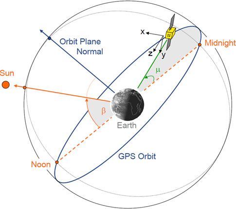
In view of the clear orbital periodicity of the clock varia- of the clock difference, the following common aspects may
tions evidenced by Figs. 1 and 2, a harmonic analysis has be noted:
been performed, in which the L1/L2 clock offset (cdt12 ) • The coefficients depend primarily on the magnitude of
and the L1/L5 - L1/L2 inter-frequency difference the sun elevation above the orbital plane (b-angle,
(cdt15 cdt12 ) are each represented by a linear-plus-peri- Fig. 3), even though a slight asymmetry with respect to
odic model function of the form a pure jbj dependence can be suspected for the 1/rev
X
4 harmonics.
f ðtÞ ¼ ða þ b tÞ þ ½ci cosðilÞ þ si sinðilÞ ð8Þ • Outside the eclipse phase (jbj [ 14 ), the 3/rev and
i¼1 4/rev terms can essentially be neglected. The amplitude
of the first- and second-order harmonics (i ¼ 1; 2)
or, equivalently,
increases by a factor of 2–3 when proceeding from high
X
4 to low sun elevations. Furthermore, the amplitude ratio
f ðtÞ ¼ ða þ b tÞ þ Ai sinðil þ Ui Þ ð9Þ si/ci remains roughly constant in this region, indicating
i¼1
a constant phase Ui for these harmonics.
The model incorporates harmonic terms up to four times • During the eclipse phase (jbj\14 ), a steep peak in the
the orbital frequency and is parameterized in terms of the clock offset and the inter-frequency clock difference
orbit angle l that is counted from the midnight line (i.e., can be noted that is triggered by the shadow entry but
the point of minimum sun–spacecraft–earth angle) and persists for a few hours after shadow exit (Figs. 1, 2).
increases almost linearly with time (Fig. 3). This reflects itself in a notable amplitude increase in
The harmonic coefficients ci and si have been esti- proportion to the eclipse duration for all harmonics.
mated from a least squares fit over consecutive 3-day data Also, a change in the relative phases of the individual
arcs over the first 8 months of SVN62 operations and phases may be noted in comparison with the eclipse-
are shown in Figs. 4 and 5 for the clock offset and the free period.
123
GPS Solut

                                   0.20

          L1/L5-L1/L2 clock [m]
                                   0.15
                                   0.10
                                   0.05
                                  -0.00
                                  -0.05
                                  -0.10
                                  -0.15
                                        2010
                                  -0.20
                                               12h                     12h                                  12h
                                    26.Sep             27.                                28.
                                   0.20
          L1/L5-L1/L2 clock [m]

                                   0.15
                                   0.10
                                   0.05
                                  -0.00
                                  -0.05
                                  -0.10
                                  -0.15
                                        2010
                                  -0.20
                                               12h                     12h                                  12h
                                    19.Nov             20.                                21.
                                   0.20
          L1/L5-L1/L2 clock [m]

                                   0.15
                                   0.10
                                   0.05
                                  -0.00
                                  -0.05
                                  -0.10
                                  -0.15
                                        2010
                                  -0.20
                                               12h                     12h                                  12h
                                    25.Dec             26.                                27.

Fig. 2 Variation of the L1/L5-minus-L1/L2 clock offset difference of SVN62 as derived from triple-frequency carrier phase observations

                                                                       variation during the eclipse phase under the condition of
                                                                       continuity at the interval boundary. In case of the inter-
                                                                       frequency clock difference, an amplitude/phase represen-
                                                                       tation was found to provide the most compact representa-
                                                                       tion, whereas the Cartesian representation appeared
                                                                       preferable for the clock offset model.
                                                                          On average, over the 8-month time interval, the L1/L5-
                                                                       minus-L1/L2 clock offset difference can be described by
                                                                       the above model with a typical accuracy of 1 cm rms. It
                                                                       thus provides a convenient way to translate legacy L1/L2
                                                                       clock products for future users of L1/L5 receivers. These
                                                                       are expected to become a standard in aviation applications,
                                                                       and the need for creating distinct L1/L5 clock products for
                                                                       L1/L5 precise point positioning may become obsolete if the
                                                                       satellite-induced inter-frequency biases can be adequately
                                                                       described by a model.
                                                                          As concerns the periodic variations of the L1/L2 clock
Fig. 3 GPS satellite orientation and angles describing the alignment   solution, the corresponding model matches the actual var-
of the sun, earth, satellite, and orbital plane                        iation over the test period with a representative accuracy of
                                                                       about 3 cm. This is clearly worse than obtained for
   Based on the data in Figs. 4 and 5, approximate                     the inter-frequency difference, but can be understood by
expressions for the harmonic coefficients in terms of jbj              the stochastic processes affecting the clock offset. Also, the
have been established for the clock offset (Table 2) and the           clock offset determination process itself suffers from larger
inter-frequency clock difference (Table 3). Favoring a very            uncertainties than the determination of the L1/L5-minus-
simple functional structure, linear approximations were                L1/L2 difference, which is directly observable from triple-
used for the eclipse-free interval (jbj [ 14 ), while cubic or        frequency carrier phase measurements. This is particularly
linear functions of jbj were adjusted to represent the                 true for the eclipse phase, where a detailed attitude model

                                                                                                                              123
GPS Solut
Fig. 4 Seasonal variation of 160.0 60.0
harmonic coefficients for C1 S1
120.0 C2 S2 40.0
SVN62 L1/L2 clock offsets. C3 S3
Shaded bars indicate the eclipse C4 S4
Beta
Beta Angle [deg]
periods 80.0 20.0
Amplitude [mm]
40.0 0.0
0.0 -20.0
-40.0 -40.0
-80.0 -60.0
10/07/01 10/08/01 10/09/01 10/10/02 10/11/02 10/12/03 11/01/03 11/02/03 11/03/06
Date
Fig. 5 Seasonal variation of 80.0 60.0
harmonic coefficients for C1 S1
60.0 C2 S2 40.0
SVN62 L1/L5-L1/L2 inter- C3 S3
Beta Angle [deg]
frequency clock offset C4 S4
Amplitude [mm]
40.0 Beta 20.0
difference. Shaded bars indicate
the eclipse periods
20.0 0.0
0.0 -20.0
-20.0 -40.0
-40.0 -60.0
10/07/01 10/08/01 10/09/01 10/10/02 10/11/02 10/12/03 11/01/03 11/02/03 11/03/06
Date
Table 2 Harmonic coefficients
Harmonics Cosine coefficient (mm) Sine coefficient (mm)
of periodic L1/L2 clock offset
variation
1/rev 20 þ 40 B31 125 160 B1 jbj 14
c1 ¼ s1 ¼ for
60 20 B2 35 þ 25 B2 jbj [ 14
2/rev 5 þ 50 B31 72 32 B31 jbj 14
c2 ¼ s2 ¼ for
55 30 B2 40 30 B2 jbj [ 14
3/rev 12 þ 27 B31 17 15 B31 jbj 14
c3 ¼ s3 ¼ for
15 10 B2 2 4 B2 jbj [ 14
4/rev 17 þ 15 B31 7 9 B13 jbj 14
c4 ¼ s4 ¼ for
2 2 jbj [ 14
With B1 ¼ jbj=14 ; B2 ¼ ðjbj 14 Þ=40
Table 3 Harmonic coefficients
Harmonics Amplitude (mm) Phase
of the L1/L5-minus-L1/L2
clock offset difference
1/rev 50 30 B31 þ30 jbj 14
A1 ¼ U1 ¼ for
20 8 B2 þ120 jbj [ 14
2/rev 68 26 B31 þ20 jbj 14
A2 ¼ U2 ¼ for
42 27 B2 þ40 jbj [ 14
3/rev 20 18 B31 30 jbj 14
A3 ¼ U3 ¼ for
2 2 B2 0 jbj [ 14
4/rev 11 9 B31 40 jbj 14
A4 ¼ U4 ¼ for
2 2 B2 0 jbj [ 14
With B1 ¼ jbj=14 ; B2 ¼ ðjbj 14 Þ=40
123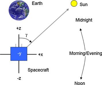
GPS Solut
-11.0 SVN62 AMC2 ADEV improves by a factor of two or more. A similar
SVN62(cor) ONSA
-11.5 PTBB
USN3
improvement can also be recognized for timescales of
YELL
-12.0 0.5–2 days.
-12.5 Aside from the triple-frequency carrier phase combina-
-13.0
tion and the L1/L2 clock offset, periodic variations are also
log ADEV
evident for the L2/L5 Melbourne–Wübbena combination
-13.5
(6). Line biases in the L2 and L5 carrier phase measure-
-14.0
ments are strongly amplified in this combination (Table 1)
-14.5
and amplitudes of 1/rev and 2/rev terms at the meter level
-15.0
are encountered in this case. Altogether, the triple-carrier
-15.5 phase combination, the L2/L5 Melbourne–Wübbena com-
-16.0 bination and the L1/L2 clock variation provide three
1.0 1.5 2.0 2.5 3.0 3.5 4.0 4.5 5.0 5.5 6.0
log tau [s]
independent observations for the line biases b1, b2, and b5
as well as the clock offset cdt. As an example, the linear
Fig. 6 Allan deviation of SVN62 rubidium clock in GPS week 1620 equations
based on CODE final products (black dotted line) and after correction 0 1
with empirical clock offset model (gray dotted line). For reference, 0 1 b1
the solid colored lines provide the Allan deviation of selected IGS þ0:285 1:546 þ1:261 0 B C
reference stations connected to high-precision masers B C B b2 C
@0 24 23 0 AB C
@ b5 A
2:546 þ1:546 0 1
cdt
0 1
would be required in the orbit and clock determination to þ26:9 þ34:1 þ23:8 þ57:8
B C
properly describe the associated phase wind-up effects. ¼ @ 501 613 416 1035 A
To assess the benefit of a model-based prediction of the þ52:1 þ45:8 þ15:4 þ58:4 ½mm
periodic clock variations, the overlapping Allan deviation 0 1
cos l 0 1
(ADEV; Riley 2008) of the CODE clock products for eDIF3
B sin l C
SVN62 has been computed for a 1-week test arc (GPS B C Be C
B C þ @ MWðL2; L5Þ A ð11Þ
week 1620, January 23–29, 2011). In this time period, the @ cos 2l A
ecdtðL1; L2Þ
b-angle varied between 24 and 29 and the periodic clock sin 2l
variations exhibited a peak-to-peak amplitude of about
20 cm. Daily offsets were adjusted to the CODE clock are obtained from the harmonic analysis of the respective
solutions to remove day-boundary discontinuities, and the measurements for a 3-day interval during the eclipse
SVN62 clock solution was referred to a single highly stable phase in mid-December 2010 (b = -10.3… - 7.8).
ground clock (Herstmonceux) over the entire arc. Fur- Approximate noise levels of
thermore, the resulting solution was detrended through a 0 1 0 1
eDIF3 5
fifth-order polynomial adjusted over the entire week. We @ eMWðL2; L5Þ A @ 100 A ð12Þ
also recall that the relativistic J2 correction (7) has been ecdtðL1; L2Þ 10 ½mm
applied to the CODE clock data which would otherwise
exhibit a superimposed 2/rev variation with 20 mm can be inferred from the scatter of the individual harmonic
amplitude. coefficients as determined from different data batches and
As illustrated in Fig. 6, the ADEV of the SVN62 clock the overall goodness of fit of the harmonic representation
in the considered period follows an approximate power law of the measurement combination.
Evidently, three equations are insufficient to solve for
ADEVðsÞ 1:4 1013 ðs=100 sÞ0:6 ð10Þ
four unknown parameters and further information would be
for time intervals s of 30 s to 2000 s and is merely 2 times required to discriminate between line bias variations and
larger than that of high performance ground clocks. For physical clock variations. It can be verified, though, that the
longer timescales, the ADEV increases again and exhibits a above observations are compatible with a vanishing clock
local maximum near s = 10,000 s. Thereafter, steep min- variation (cdt = 0), in which case line bias variations with
ima are attained at the orbital period (approx. 43,080 s) and amplitudes of 20–70 mm and a formal uncertainty of
integer multiples thereof, which clearly reflects the pres- 20 mm are obtained for the respective 1/rev and 2/rev
ence of 1/rev clock variations. When correcting the clock harmonics on the L1, L2, and L5 carriers. On the other
data with the empirical harmonic model, the ‘‘bump’’ hand, the observations are likewise compatible with the
between 3,000 and 40,000 s is notably flattened and the assumption of vanishing line biases in both the L1 and L2
123GPS Solut
0.20
2010/09/27
2010/12/05
0.15 2010/12/26
0.10
L1/L5-L1/L2 clock [m]
0.05
-0.00
-0.05
-0.10
-0.15
-0.20
0 20 40 60 80 100 120 140 160 180
Fig. 7 Sun illumination of the GPS spacecraft gamma [deg]
Fig. 8 Variation of the L1/L5-minus-L1/L2 clock difference with the
carriers (b1 = b2 = 0). The observed variations in the tri- sun–spacecraft–earth angle (c) for selected 3-day arcs at maximum b-
ple-frequency combination would then reflect the changing angle (b = -54; red), at the start of the eclipse season (b = -14;
L5 carrier phase bias, while the apparent L1/L2 clock offset green), and at the center of the eclipse phase (b = 0; blue). At low c
cdt12 would be identical to the actual clock offset cdt. angles, the curve is traversed in a clockwise manner
The rate of energy absorbed by each panel depends
Thermal considerations exclusively on c and is proportional to the projection of the
sun direction unit vector on the respected surface:
The dominant b-angle dependency and the impact of
eclipses strongly suggest satellite internal temperature Q_ þz;in / maxðcosðcÞ; 0Þ Q_ z;in / maxð cosðcÞ; 0Þ
variations due to varying sun illumination as the root cause Q_ þx;in / sinðcÞ ð13Þ
of the observed clock offset and inter-frequency clock bias
variations. The GPS-specific attitude control concept On average, the incoming energy is compensated by
implies that the sun direction is always contained in the x/z- dissipation and re-radiation and a constant rate Q_ out ¼ Q_ in
plane of the spacecraft. In the course of each orbit, the sun can be assumed in the simplest case. The panel temperature
direction vector oscillates about the ?x-axis (Fig. 7) and is proportional to the stored energy Q and is thus obtained
the sun–spacecraft–earth angle c varies between a mini- from the time integral of the irradiance:
mum of jbj at midnight (l = 0) and a maximum of Z
180 jbj at noon (l = 180). Accordingly, the ?x panel DT / Q ¼ ðQ_ in Q_ in Þdt ð14Þ
remains continuously sun-lit (except during eclipses),
whereas the ?z and -z panels are only illuminated during Figure 9 illustrates the modeled irradiance (Q_ in Q_ in ) and
one half of each orbit centered on midnight and noon, the associated temperature variation for each of the three
respectively. The ?y and -y panels always see the sun at a panels over a full orbit in case of high and low b-angles. It
zero elevation angle except during deviations from the can be recognized that the ?x panel temperature variation
nominal attitude that may occur during noon and midnight exhibits a pronounced 2/rev periodicity, whereas the ?z
turns at low b-angles due to limited yaw slew rates and -z panels show a dominant 1/rev temperature variation
(Dilssner 2010). (in anti-phase). In addition, a smaller (20%) variation at
While the illumination itself depends exclusively on the twice the orbital frequency is obtained with an identical
sun–spacecraft–earth angle, the same does not hold for the phase for both panels. On the other hand, no relevant 3/rev
observed clock offset and inter-frequency bias. As illus- or 4/rev contributions are observed, which is consistent
trated in Fig. 8 for the variation of cdt15 cdt12 versus c, a with the lack of such terms in the variations of the clock
distinct figure-of-eight shape is obtained, which evidences offset (cdt12 ) and the inter-frequency difference
a delayed response of the observed clock offset difference (cdt15 cdt12 ) outside the eclipse period. Furthermore, the
to the sun illumination. This hysteresis is likewise indicated simple thermal model offers a qualitative explanation for
by the relative phase shift of the 1/rev and 2/rev harmonics the changing amplitude of the 1/rev and 2/rev variations
(Table 3). (Tables 2, 3), which increase by a factor of 2–3 when
To better understand the observed variations, we con- changing from high sun elevations (b = 54) to low ele-
sider a basic model of the spacecraft heating by the sun. vations (b = 14) in the eclipse-free season.
123GPS Solut
Normalized temperature variation
Fig. 9 Modeled irradiance 1 4
(left) and temperature variations
Irradiance (normalized)
DT of the ?z (blue), ?x (red)
and -z (green) panels for 0.5 2
different sun elevations above
the orbital plane (top: b = 54; 0 0
bottom: b = 14). Dotted and
dashed lines illustrate the
−0.5 +z −2 ΔT
decomposition into 1/rev and 1/rev
−z
2/rev harmonics +x 2/rev
−1 −4
0 45 90 135 180 225 270 315 360 0 45 90 135 180 225 270 315 360
Orbit angle (μ) [deg] Orbit angle (μ) [deg]
Normalized temperature variation
1 4
Irradiance (normalized)
0.5 2
0 0
−0.5 +z −2 ΔT
−z 1/rev
+x 2/rev
−1 −4
0 45 90 135 180 225 270 315 360 0 45 90 135 180 225 270 315 360
Orbit angle (μ) [deg] Orbit angle (μ) [deg]
Unfortunately, it is difficult to gain further insight from of GPS satellites. However, the harmonic perturbations
the model without a more detailed knowledge of the internal exceed the stochastic clock variations for the first Block IIF
structure and thermal characteristics of the GPS satellite. spacecraft in view of the high clock quality and become
Fundamentally, periodic surface temperature changes will well observable even in shorter data arcs. For the first time,
propagate into the spacecraft body with an attenuation and a study of inter-frequency biases independent of the
delay, i.e. phase shift, that both depend on the frequency of physical clock behavior is, furthermore, enabled through
these variations and the material properties (Alonso and the availability of triple-frequency measurements.
Finn, 1967). On the Block IIF satellites, the atomic clocks Fundamentally, orbital harmonics in the observed GPS
as well as the L1 transmitter are mounted on the -y side of clock offset solution may be caused through coupling with
the spacecraft and the opposite (?y) panel holds the L2 and orbit determination uncertainties, oscillator frequency
L5 transmitters (Dorsey et al. 2006). From the above con- variations and line bias variations. GPS orbit determination
siderations, we can expect a superposition of 1/rev and 2/rev errors are less than a few centimeters for current precise
harmonics in the temperature of each of these navigation orbit products (Griffiths and Ray 2009) and typically
payload elements. Amplitudes and phases of these har- dominated by 1/rev periods. A possible contamination of
monics will be different for the individual devices but the clock solution with once-per-rev orbit errors must
cannot be predicted without further information. therefore be assumed (Senior et al. 2008), but 2/rev har-
monics are considered to be mostly unaffected. As regards
a thermal sensitivity of the atomic frequency standard,
Discussion timing errors of ±0.25 ns (±7.5 cm) have been predicted
by Wu (1996) for the Block IIR satellites based on an
As shown by Senior et al. (2008) based on a long-term expected temperature variation of ±2.5 K outside eclipses.
spectral analysis of precise GPS ephemeris products, Following Dupuis et al. (2010), the rubidium clocks of the
orbital harmonics with amplitudes of up to several nano- Block IIF satellites are mounted on a thermally isolated
seconds can be identified in the observed clock offsets of sub-panel (along with the frequency distribution unit) for
all generations of GPS satellites. The amplitude of these which a peak-to-peak temperature variation of less than
sub-daily harmonics exhibits evident seasonal variations 0.5 K has been observed in SVN62 onboard measurements.
and increases during the eclipse phase. Despite notable In addition, the new clock benefits from a baseplate tem-
improvements in the Block IIF rubidium clock with respect perature controller (BTC), which further reduces the sen-
to its predecessors, clock variations with orbital and sub- sitivity to external temperature variations by up to a factor
orbital periodicity are likewise observed for this latest type of 50. These numbers would suggest a negligible
123GPS Solut
contribution of temperature-induced frequency variations variations as well as frequency-dependent line bias varia-
on the observed variance of the apparent SVN62 clock, but tions in the radio frequency chain can be suspected.
more detailed information and measurements appear nec- However, the available measurements do not allow a
essary to substantiate this view. conclusive discrimination of the two contributions. Using a
Regarding the impact of temperature-dependent line harmonic analysis, the periodic variations of the apparent
biases, it is important to note that the inter-frequency clock clock can be modeled with an accuracy of about 0.1 ns
difference is derived from geometry-free observations and (3 cm). Even though the root cause of the apparent clock
therefore fully independent of orbit errors or physical clock variation remains unclear, a clock correction based on the
offset variations. The triple-frequency carrier phase com- empirical model is shown to notably reduce the Allan
bination therefore provides an unambiguous evidence for variance at timescales of 1–12 h. It may thus contribute to
the presence of thermally induced line bias variations in at improved clock predictions over sub-daily intervals and to
least some of the three carriers. Similar considerations hold extending the validity of broadcast clocks.
for the dual-frequency L2/L5 Melbourne–Wübbena com-
bination. Despite the availability of triple-frequency Acknowledgments The authors acknowledge the vital role of the
International GNSS Service to this analysis. Orbit and clock solutions
observations and multiple linear combinations, it is not for SVN62 have been contributed by the Center for Orbit Determi-
possible, though, to uniquely separate the line biases and nation in Europe (CODE) based on observations of the IGS network.
physical clock offset variations. The observation types CODE is a joint venture between the Astronomical Institute of the
considered in the present study (i.e., the L1/L2 clock University of Bern (AIUB, Bern, Switzerland), the Federal Office of
Topography (swisstopo, Wabern, Switzerland), the Federal Agency
solutions, the triple-carrier combination, and the L2/ for Cartography and Geodesy (BKG, Frankfurt, Germany), and the
L5 MW combination) are generally compatible with the Institut für Astronomische und Physikalische Geodäsie of the Tech-
assumption of a vanishing oscillator frequency variation, nische Universität München (IAPG/TUM, Munich, Germany). It acts
and the observed periodic variations might thus be caused as a global analysis center of the IGS since June 1992. Triple-fre-
quency observations have been provided by the CONGO multi-GNSS
exclusively by line bias variations. However, the validity of network. The contributions of all network partners (Deutsches Zen-
this assumption cannot be assessed due to a lack of public trum für Luft- und Raumfahrt, Bundesamt für Kartographie und
information on the Block IIF navigation payload charac- Geodäsie, Technische Universität München, Deutsches GeoFors-
teristics and the satellite internal temperature variations. chungsZentrum, Centre National d’Etudes Spatiales, Geoscience
Australia) and local station hosts are gratefully acknowledged.
Such measurements are strongly encouraged to identify
and potentially remove the root cause of the Block IIF
apparent clock variations.
References
Alonso M, Finn EJ (1967) Fundamental university physics, vol II,
Summary and conclusions fields and waves. Addison-Wesley, Reading
Bock H, Dach R, Jäggi A, Beutler B (2009) High-rate GPS clock
An analysis of apparent clock variations of the first Block corrections from CODE: support of 1 Hz applications. J Geodesy
83(11):1083–1094. doi:10.1007/s00190-009-0326-1
IIF satellite SVN62 has been performed. Orbit-periodic Braschak M, Brown H Jr., Carberry J, Grant T, Hatten G, Patocka R,
variations have been characterized for the apparent L1/L2 Watts E (2010) GPS IIF satellite overview, ION-GNSS-2010,
clock offset of the new rubidium frequency standard and 21–24 Sept 2010, Portland, OR
the L1/L5-minus-L1/L2 clock difference. A thermal origin Dach R, Brockmann E, Schaer S, Beutler G, Meindl M, Prange L,
Bock H, Jäggi A, Ostini L (2009) GNSS processing at CODE:
of these variations is evidenced by eclipse transits and the status report. J Geodesy 83(3–4):353–365. doi:10.1007/s00190-
observed dependence of the individual harmonics on the 008-0281-2
sun elevation above the orbital plane. Dilssner F (2010) GPS IIF-1 satellite—antenna phase center and
The inter-frequency clock difference of 10–20 cm is attitude modeling. InsideGNSS, Sept 2010, pp 59–64
Dorsey AJ, Marquis WA, Fyfe PM, Kaplan ED, Wiederholt LF
decoupled from the actual oscillator performance and can (2006) GPS system segments. In: Kaplan ED, Hegarty CJ (eds)
exclusively be attributed to line bias variations in the radio Understanding GPS—principles and applications, 2nd edn.
frequency chain. An empirical model is established to Artech House, Norwood, pp 67–112
describe the orbital and seasonal variations with a repre- Dow JM, Neilan RE, Rizos C (2009) The international GNSS service
in a changing landscape of global navigation satellite systems.
sentative accuracy of 30 ps (1 cm). This will enable a con- J Geodesy 83(3–4):191–198. doi:10.1007/s00190-008-0300-3
sistent use of legacy L1/L2 clock products for future aviation Dupuis RT, Lynch TJ, Vaccaro JR, Watts ET (2010) Rubidium
users with L1/L5-only receivers. In addition, knowledge of frequency standard for the GPS IIF program and modifications
the inter-frequency biases is of relevance for ionospheric for the RAFSMOD program. ION-GNSS-2010, 21–24 Sept
2010, Portland, OR
investigations using triple-frequency measurements. Griffiths J, Ray JR (2009) On the precision and accuracy of IGS
Concerning the observed variations of the L1/L2 clock orbits. J Geodesy 83(3–4):277–287. doi:10.1007/s00190-008-
solution, both thermally induced oscillator frequency 0237-6
123GPS Solut
Kouba J (2004) Improved relativistic clock correction due to earth Dr. Urs Hugentobler is a full
oblateness. GPS Solut 8(3):170–180. doi:10.1007/s10291-004- professor since 2006 at the
0102-x Institute for Astronomical and
Kouba J (2009) A simplified yaw-attitude model for eclipsing GPS Physical Geodesy of Technische
satellites. GPS Solut 13:1–12. doi:10.1007/s10291-008-0092-1 Universität München, Germany,
Montenbruck O, Hauschild A, Steigenberger P, Langley RB (2010a) and head of the Research
Three’s the challenge: a close look at GPS SVN62 triple- Establishment Satellite Geod-
frequency signal combinations finds carrier-phase variations on esy. His research activities focus
the new L5. GPS World 21(8):8–19 on precise applications of GNSS
Montenbruck O, Hauschild A, Hessels U (2010b) Characterization of such as positioning, precise
GPS/GIOVE sensor stations in the CONGO network. GPS Solut orbit determination, reference
15(3):193–205. doi:10.1007/s10291-010-0182-8 frame realization, and time
Riley WR (2008) Handbook of frequency stability analysis, NIST transfer.
special publication 1065. National Institute of Standards and
Technology, Boulder, CO
Senior K (2010) SVN62 clock analysis using IGS data, IGSMAIL- Rolf Dach received his Ph.D.
6218, 6 Aug 2010, http://igscb.jpl.nasa.gov/pipermail/igsmail/ thesis in geodesy at the Institut
2010/000051.html für Planetare Geodäsie of the
Senior K, Ray JR, Beard RL (2008) Characterization of periodic University of Technology in
variations in the GPS satellite clocks. GPS Solut 12(3):211–225. Dresden, Germany. Since 1999,
doi:10.1007/s10291-008-0089-9 he has been working as a sci-
Spits J, Warnant R (2008) Total electron content monitoring using entist at AIUB, where he is the
triple frequency GNSS data: a three-step approach. J Atmo- head of the GNSS Research
spheric Solar-Terr Phys 70(15):1885–1893. doi:10.1016/j.jastp. Group since 2006. He leads the
2008.03.007 development of the Bernese
Teunissen PJG, Joosten P, Tiberius C (2002) A comparison of TCAR, Software package and is
CIR and LAMBDA GNSS ambiguity resolution. ION-GPS- responsible for the activities of
2002, Portland, OR, pp 2799–2808 the CODE analysis center of the
Tsai Y-H, Chang F-R, Yang W-C, Ma C-L (2004) Using multi- IGS.
frequency for GPS positioning and receiver autonomous integ-
rity monitoring. In: Proceedings of the 2004 IEEE international Dr. Peter Steigenberger works
conference on control applications, Taipei, Taiwan, 2–4 Sept at the Institute of Astronomical
2004 and Physical Geodesy of Tech-
Vannicola F, Beard R, White J, Senior K, Kubik A, Wilson D (2010) nische Universität München
GPS Block IIF rubidium frequency standard life test. ION- (TUM, Munich, Germany). His
GNSS-2010, 21–24 Sept 2010, Portland, OR current research interests
Wu A (1996) Performance evaluation of the GPS Block IIR time include global GNSS solutions
keeping system. In: Breakiron L (ed) Proceedings of the 28th and the analysis of the GNSS-
annual precise time and time interval applications and planning derived parameter time series,
meeting. US Naval Observatory, Reston, pp 441–453 e.g., troposphere zenith delays,
Wu JT, Wu SC, Hajj GA, Bertiger WI, Lichten SM (1993) Effects of station coordinates, satellite
antenna orientation on GPS carrier phase. Manuscripta Geodae- orbits, and Earth rotation
tica 18:91–98 parameters.
Author Biographies Dr. André Hauschild is a sci-
entific staff member at DLR’s
Dr. Oliver Montenbruck is German Space Operations Cen-
head of the GNSS Technology ter (GSOC). His field of work
and Navigation Group at DLR’s focuses on precise real-time
German Space Operations Cen- orbit and clock estimation for
ter, where he started work as a GNSS satellites as well as
flight dynamics analyst in 1987. multi-GNSS processing using
His current research activities modernized GPS and new
comprise space-borne GNSS satellite navigation systems.
receiver technology, autono-
mous navigation systems,
spacecraft formation flying,
precise orbit determination, and
multiconstellation GNSS.
123You can also read