OWNER'S MANUAL BLUE GENIUSTOUCH CONTROL MASTER CONTROL PANELS - Blue Giant
←
→
Page content transcription
If your browser does not render page correctly, please read the page content below
OWNER’S MANUAL
                                                            BLUE GENIUS™TOUCH CONTROL
                                                                  MASTER CONTROL PANELS

ACTUAL PRODUCT MAY NOT APPEAR EXACTLY AS SHOWN

                     WARNING
  Do not operate or service this product unless you have
  read and fully understand the entire contents of this
  manual. Failure to do so may result in property damage,
  bodily injury or death.

STARTING FROM MARCH, 2016 / SERIAL # 411892                        ISSUE DATE: JULY 15, 2020 REV.1.1 (PART # 038-918E)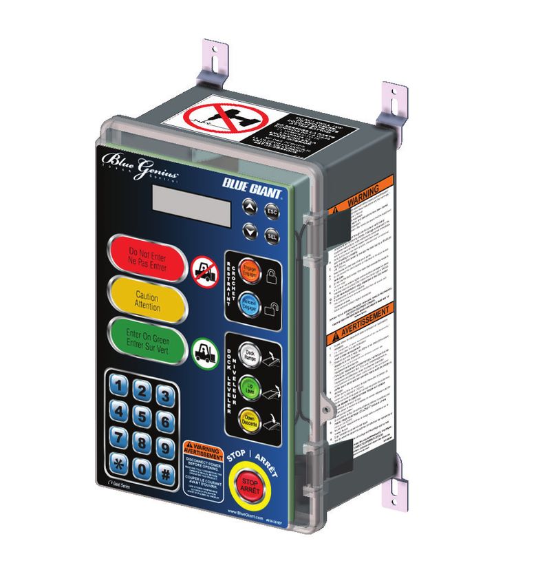
BLUE GENIUS™ TOUCH CONTROL MASTER CONTROL PANELS—OWNER’S MANUAL
TABLE OF CONTENTS
1.0 ABOUT BLUE GENIUS™ TOUCH CONTROL MASTER CONTROL PANELS 3
1.1 OWNER’S PURCHASE RECORD 3
2.0 INTRODUCTION 4
2.1 WARRANTY INFORMATION 4
2.2 EXCLUSION OF LIABILITY 4
2.3 MANUFACTURER’S NOTE 4
2.4 OWNER’S RESPONSIBILITY 5
3.0 SAFETY MESSAGE COLOR IDENTIFICATION 6
3.1 OPERATIONAL SAFETY WARNINGS 6
4.0 LOCKOUT / TAGOUT PROCEDURE AND RULES 7
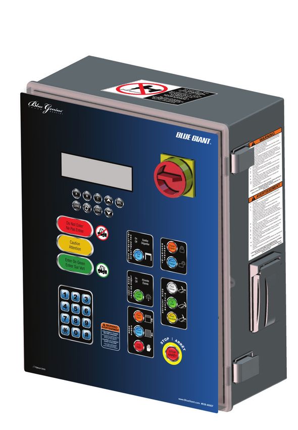
4.1 ROTARY DISCONNECT: PLATINUM SERIES 7
5.0 CONTROL PANEL OPERATION: GOLD SERIES III 8
5.1 BUTTON FUNCTION: GOLD SERIES III 8
5.2 CONTROL SECTIONS: GOLD SERIES III 9
6.0 RECOMMENDED SPARE PARTS: GOLD SERIES III 10
7.0 EQUIPMENT COMPONENT ILLUSTRATIONS: GOLD SERIES III 11
7.1 COMPONENTS AS SHIPPED CHECK LIST: GOLD SERIES III 11
7.2 MECHANICAL ASSEMBLY: GOLD SERIES III 12
7.3 GENERAL DIMENSIONS: GOLD SERIES III 13
8.0 CONTROL PANEL OPERATION: PLATINUM SERIES 14
8.1 BUTTON FUNCTION: PLATINUM SERIES 14
8.2 CONTROL SECTIONS: PLATINUM SERIES 15
9.0 RECOMMENDED SPARE PARTS: PLATINUM SERIES 17
10.0 EQUIPMENT COMPONENT ILLUSTRATIONS: PLATINUM SERIES 18
10.1 COMPONENTS AS SHIPPED: PLATINUM SERIES 18
10.2 MECHANICAL ASSEMBLY: PLATINUM SERIES 19
10.3 GENERAL DIMENSIONS: PLATINUM SERIES 21
11.0 DECAL IDENTIFICATION AND LOCATION: GOLD SERIES III AND PLATINUM SERIES 22
12.0 STOP PROCEDURE: GOLD SERIES III AND PLATINUM SERIES 23
13.0 OPERATING INSTRUCTIONS: GOLD SERIES III AND PLATINUM SERIES 24
13.1 ALTERNATIVE METHODS OF OPERATION: GOLD SERIES III AND PLATINUM SERIES 25
14.0 ENGAGING THE OVERRIDE FEATURE: GOLD SERIES III AND PLATINUM SERIES 26
14.1 RELEASING THE OVERRIDE FEATURE: GOLD SERIES III AND PLATINUM SERIES 27
15.0 EXTERIOR TRAFFIC LIGHT / MIRROR IMAGE SIGN: GOLD SERIES III AND PLATINUM SERIES 28
16.0 CONTROL PANEL LCD MESSAGES: GOLD SERIES III AND PLATINUM SERIES 29
17.0 WIRING DIAGRAMS: GOLD SERIES III AND PLATINUM SERIES 29
17.1 WIRING DIAGRAM - 115V SINGLE PHASE: GOLD SERIES III (SVR303 & FH COMBO) 30
17.2 WIRING DIAGRAM - 230V SINGLE PHASE: GOLD SERIES III (TL85 REMOTE & FH COMBO) 31
17.3 POWER WIRING DIAGRAM - 230 - 575V THREE PHASE: PLATINUM SERIES (SVR303 & VL COMBO) 32
17.4 CONTROL WIRING DIAGRAM - 230 - 575V THREE PHASE: PLATINUM SERIES (SVR303 & VL COMBO) 34
2 ISSUE DATE: JULY 15, 2020 REV.1.1 (PART # 038-918E)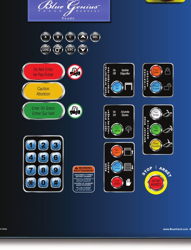
BLUE GENIUS™ TOUCH CONTROL MASTER CONTROL PANELS—OWNER’S MANUAL

1.0 ABOUT BLUE GENIUS™ TOUCH CONTROL MASTER CONTROL PANELS

Blue Genius™ Touch Control Master Control Panels (MCP) represent the highest
level in loading dock safety and productivity.
                                                                                                                    LEGEND
                                                                                                                  Section applies only to
The Master Control Panels consolidate the controls for multiple interconnected                                    Blue Genius™ Gold Series III
dock devices:
                                                                                                                  Section applies only to
•         Dock leveler                                                                                            Blue Genius™ Platinum Series
•         Vehicle restraint
•         Overhead door (standard with Platinum Series, optional with Gold Series)                                Section applies to both
•         Inflatable seal (standard with Platinum Series, optional with Gold Series)                              Blue Genius™ control panels
•         Dock lights (standard with Platinum Series, optional with Gold Series)
•         Communications - Traffic lights (trailer and forklift) and LCD menu screen

The equipment operation sequence is structured to ensure safety and efficiency. The LCD menu screen provides ongoing equipment
status as well as instructions for operating and troubleshooting. The interior and exterior LED light communication system displays
safety signals to truck drivers and dock personnel. The rotary disconnect (Platinum Series only) cuts power to the unit for routine
servicing and maintenance.

The panel’s NEMA4X-rated polycarbonate enclosure is wet and corrosion-resistant, ensuring seamless operation in the wash-down zone
and outdoor locations. The control panels are also compatible with operations that must adhere to the FDA’s high cleaning standards,
such as pharmaceutical and chemical handling locations.

1.1 OWNER’S PURCHASE RECORD

                                                    OWNER’S PURCHASE RECORD
             Please record information for future inquiries and to validate warranty. (See Section 2.1 for warranty validation)

Dealer:                                                                                        Date in Service:

                                                                                               Number of Units:

Gold Series III                                     Platinum Series

Serial Number:                                                                                 Door #:

Serial Number:                                                                                 Door #:

Serial Number:                                                                                 Door #:

Serial Number:                                                                                 Door #:

The manufacturer offers a full line of dock levelers, dock safety equipment, accessories, ergonomic and scissor lift equipment, seals and
shelters, and industrial trucks. Concurrent with a continuing product improvement program, specifications are subject to change without
notice (see Section 2.2 "Exclusion of Liability" of this manual). Please contact the manufacturer for latest information. Some features
illustrated may be optional in certain market areas.

                                                                       NOTICE

              See Section 11.0 "Decal Identification and Location: Gold Series III and Platinum Series," item #3 for serial number location.

                                                                                             ISSUE DATE: JULY 15, 2020 REV.1.1 (PART # 038-918E)   3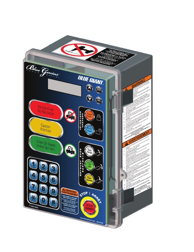
BLUE GENIUS™ TOUCH CONTROL MASTER CONTROL PANELS—OWNER’S MANUAL

2.0 INTRODUCTION                                                      2.1 WARRANTY INFORMATION

The following is a quick reference to important procedures that       Thank you for purchasing Blue Giant products. We appreciate
must be followed while using the MCP. It is not intended to cover,    your business, and are confident that our product will serve
or suggest that it does cover, all procedures necessary to ensure     you for many years to come. In the event that you experience a
safe operation. All operators should be aware of and abide by all     problem with our product, our Warranty Center is here to support
workplace safety regulations applicable to the operation of the       the Blue Giant product(s) that you have purchased.
MCP. These laws and regulations include but are not limited to:

•   The Occupational Safety and Health Act                              To validate warranty on recently purchased equipment,
•   Canada Occupational Health and Safety Regulations                   please complete and submit your information with our
•   Occupational Safety and Health Acts for Individual States            online Warranty Registration at www.BlueGiant.com.
    (USA)

For additional information on these regulations as well as industry   For more information about Blue Giant Warranty Support, please
standards that may apply to this product, please contact:             contact your local Blue Giant Equipment dealer, representative or
                                                                      authorized partner near you. You may also visit www.BlueGiant.
                                                                      com or phone 1.905.457.3900.

                                                                       DEALER INFORMATION

                                                                       Name:

American National Standards Institute (ANSI)                           Contact:
1430 Broadway
                                                                       Telephone:
New York, NY 10018
Telephone: 212.642.4900
www.ansi.org                                                          * NOTE that failure to validate warranty at the time of receipt can
                                                                      seriously affect the outcome of any claim.
Also a member of:
                                                                      2.2 EXCLUSION OF LIABILITY

                                                                      The manufacturer assumes no liability for damage or injury to
                                                                      persons or property which occur as a result of defects or faults
                                                                      in or incorrect use of the control panel. The manufacturer also
                                                                      assumes no liability for lost profits, operating downtimes, or similar
Loading Dock Equipment Manufacturers                                  indirect losses incurred by the purchaser. Injury to third parties,
A Product Section of Material Handling Industry of America            irrespective of its nature, is not subject to compensation.
A Division of Material Handling Industry
8720 Red Oak Blvd, Suite 201                                          The manufacturer reserves the right to make changes at any time
Charlotte, NC, 28217-3992                                             to the modules, components, and accessories, concurrent with
Telephone: 704.676.1190                                               its continuing product improvements and development program.
www.mhi.org/lodem                                                     Specifications, operating instructions, and illustrations included in
                                                                      this manual are subject to change without notice. Please contact
                                                                      manufacturer for the latest information.

                                                                      2.3 MANUFACTURER’S NOTE

                                                                      The control panel has been carefully inspected and tested at the
                                                                      manufacturer’s plant prior to shipment, but should be checked
                                                                      upon receipt for transport damage. Any observed transport
                                                                      damage is to be listed on the signed copy of the freight document.
                                                                      Notify the freight forwarder of any damage WITHIN 48 HOURS.

4   ISSUE DATE: JULY 15, 2020 REV.1.1 (PART # 038-918E)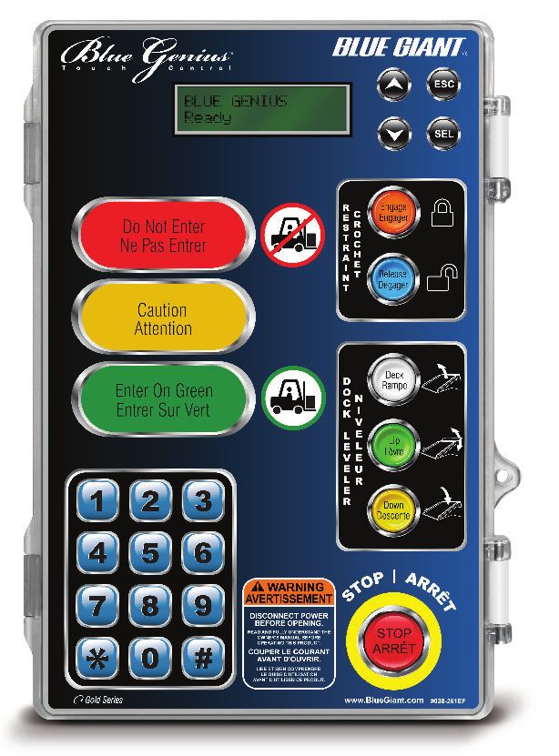
BLUE GENIUS™ TOUCH CONTROL MASTER CONTROL PANELS—OWNER’S MANUAL

2.4 OWNER’S RESPONSIBILITY

1. The owner should recognize the inherent danger of the             7. The owner or a trained and authorized representative shall
   interface between the dock and the freight carrier. The owner        verify that all freight carrier brakes have been applied and a
   should, therefore, train and instruct operators in the safe use      vehicle restraint and/or wheel chocks properly engaged before
   of the dock equipment and accessories in accordance with the         cross-docking procedures begin. For safety reasons trailers
   manufacturer’s recommendations.                                      must be held securely in place to avoid accidental separation
                                                                        from the loading dock.
2. The owner should thoroughly familiarize themselves with
   the following procedures and specifications, and request          8. Unless specifically agreed to in writing by Blue Giant Equipment
   immediate replacement of all manufacturer-supplied                   Corporation at the time of order (and prior to manufacture), all
   documents that are missing, damaged, or otherwise illegible.         Blue Giant Dock equipment is sold as a complete offering and
   Below is a list of Best Practices for dock equipment usage and       must not be altered or added to in any manner (which includes
   maintenance.                                                         configuration and function) without written permission from
                                                                        an authorized manufacturer’s representative. These changes
      •   Commissioning instructions                                    shall also satisfy all safety recommendations of the original
      •   Operating instructions                                        equipment manufacturer for the particular application of the
      •   Daily maintenance procedures checklist                        dock equipment.
      •   Inspections procedures
      •   Recommended spare parts lists                              9. If, at the request of the owner, Blue Giant does not supply
                                                                        all or some of the dock equipment power unit and/or control
   Upon receipt of any newly purchased dock equipment,                  panel components, the owner shall assume responsibility for
   the owner shall verify the presence of owner’s manuals,              any and all operational and safety issues associated with the
   operating placards, and any other documentation necessary            resulting configuration.
   for training dock personnel how to use the equipment safely
   and effectively.

3. All Blue Giant dock equipment should undergo regularly
   scheduled planned maintenance. Maintenance requirements
   will vary according to usage frequency and application,
   so the owner shall consult with their authorized Blue Giant
   distributor for schedule recommendation. Written records of
   the performance of these procedures should be kept as per
   warranty requirements.

4. Dock equipment that is structurally damaged, experiencing
   performance irregularities, or has been potentially
   compromised shall be removed from service until a trained
   and authorized manufacturer’s representative can conduct an
   inspection and perform any necessary repairs.

5. As with any piece of machinery, dock equipment requires
   routine   maintenance,     lubrication,  and    adjustments.
   Recommended procedures are itemized in the Planned
   Maintenance Program (PMP) checklist included in installation
   and technical manuals. It is recommended that for anything
   other than the basic maintenance procedures outlined in this
   manual, you contact your local Blue Giant representative.

6. The owner shall ensure that all name plates and safety labels
   are in place and legible, and that the appropriate manuals
   are provided to authorized users. Replacement name plates,
   safety labels, and manuals are available through the Blue
   Giant Aftermarket Department. See “Decal Identification and
   Location” section in this manual for more information.

                                                                                  ISSUE DATE: JULY 15, 2020 REV.1.1 (PART # 038-918E)   5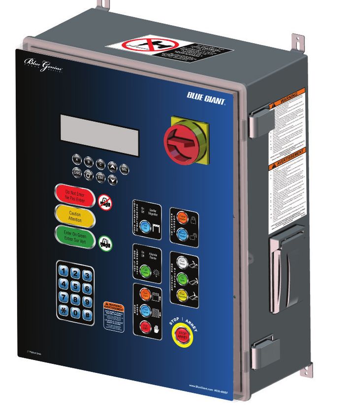
BLUE GENIUS™ TOUCH CONTROL MASTER CONTROL PANELS—OWNER’S MANUAL

3.0 SAFETY MESSAGE COLOR IDENTIFICATION

This manual includes color-coded safety messages that clarify instructions and specify areas where potential hazard exists. To prevent
the possibility of equipment damage and serious injury or death, please observe strictly the instructions and warnings contained in
the messages. If warning decals become damaged or missing, replace them immediately. Avoid accidents by recognizing dangerous
procedures or situations before they occur.

                                      DANGER                                                                      NOTICE

                Serious injury or death will likely occur if the                           Procedures marked notice must be followed in order
                       instructions are not followed.                                              to prevent damage to machinery.

                                     WARNING                                                                         CAUTION

                   Serious injury or death may occur if the                            Instructions marked caution concern safe operating procedure.
                        instructions are not followed.                                          Failure to comply may result in personal injury.

3.1 OPERATIONAL SAFETY WARNINGS

                                                                             DANGER

    1. Do not operate the dock equipment while anyone is standing in its path.
    2. Lift the dock equipment with suitable hoisting equipment only. Do not stand under the dock equipment or any heavy object while it is being
       hoisted.
    3. BEFORE BEGINNING ANY SERVICE PROCEDURES:
       Disconnect the power and follow all lockout / tagout procedures outlined in this manual.

                                                                             WARNING

    1.   Installation must be performed only by trained and authorized personnel.
    2.   Prior to installation, place adequate barriers to prevent vehicle traffic from entering the work area.
    3.   Any electrical work must be performed by qualified personnel only.
    4.   Do not remove the wheel chocks until loading / unloading is finished and the truck is cleared for departure or the vehicle restraint has been
         released and the lights have changed to RED inside and GREEN outside.

                                                                           NOTICE

    1.   Do not ground welding equipment to any electrical components.
    2.   Do not allow the drill to go too deeply into the control box, as damage may occur to the control systems.
    3.   Never use air to blow debris from the control box. Use a vacuum to perform any necessary cleaning.
    4.   Do not connect green ground lead into control box or junction box until all welding has been completed.

                                                                             CAUTION

    1.   Only trained personnel should operate or service this equipment.
    2.   Do not operate the dock equipment until the transport vehicle is parked against the dock bumpers.
    3.   Always park the dock equipment after use (ensure that the lip is safely parked in the lip keepers).
    4.   Conduct routine inspections and maintenance. Failure to do so could cause equipment damage and or personal injury.
    5.   Always call your authorized service representative or manufacturer immediately if a malfunction occurs.
    6.   Always return the restraint arm to the parked position after use.

6        ISSUE DATE: JULY 15, 2020 REV.1.1 (PART # 038-918E)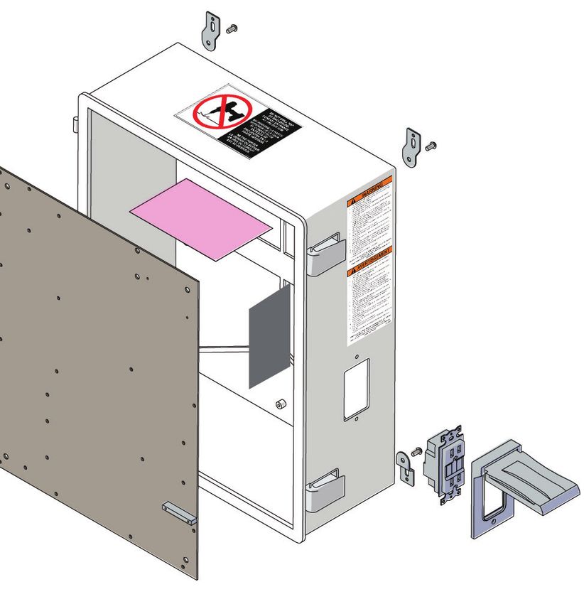
BLUE GENIUS™ TOUCH CONTROL MASTER CONTROL PANELS—OWNER’S MANUAL

                                                                        WARNING
     Always lockout and tagout any power source before performing any work on any electrical devices or electrical controls according to OSHA
                                                regulations and approved local electrical codes.

4.0 LOCKOUT / TAGOUT PROCEDURE AND RULES                                      4.1 ROTARY DISCONNECT: PLATINUM SERIES

In accordance with the rules and regulations of the Occupational              The Platinum Series has a built-in rotary disconnect. The disconnect
Safety and Health Administration (OSHA), all affected employees               has two switch positions: ON and OFF, and can be locked in either
must be notified that the machine or equipment will be shut down              position.
and locked out to perform repair or maintenance work. The work
area must be checked to ensure that all personnel have been
removed or safely repositioned. The machine or equipment power
supply shall be locked in the OFF position or disconnected from
the energy source. Blue Giant strongly recommends that only
OSHA-approved lockout devices and procedures be utilized.
                                                                                                                      OFF

The energy isolating device must bear a prominent warning tag
indicating that work is being done on the equipment and the
name of the authorized employee responsible for the lockout. It is
mandatory that tagout notices not be susceptible to deterioration
or illegibility due to weather conditions or exposure to chemicals
and moisture.
                                                                                                  DO
                                                                                                OP N
                                                                                                  ER OT
                                                                                                 Th
                                                                                                    AT
                                                                                                    i
                                                                                                on s Loc
                                                                                                      E
                                                                                                  ly b k/T
                                                                                                      e r ag
                                                                                                         em m
                                                                                                           ov ay
                                                                                                             ed
                                                                                                                by
                                                                                                                  :

                                                                              Approved way to lockout / tagout.

                                       D
                                     OP O N
                                       ER OT
                                     Th
                                         AT
                                        is
                                    on Loc
                                            E
                                      ly b k/T
                                           e r ag
                                              em m
                                                ov ay
                                                  ed
                                                     by
                                                       :

Approved way to lockout / tagout.

                                                                                            ISSUE DATE: JULY 15, 2020 REV.1.1 (PART # 038-918E)   7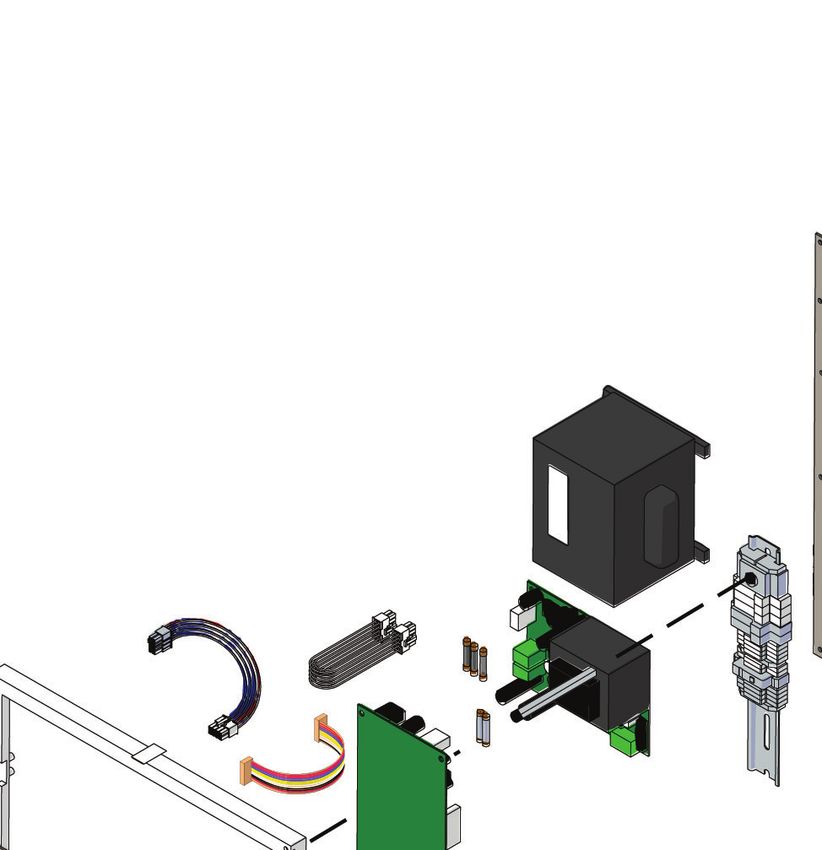
BLUE GENIUS™ TOUCH CONTROL MASTER CONTROL PANELS—OWNER’S MANUAL
5.0 CONTROL PANEL OPERATION: GOLD SERIES III
Controls combinations of all supported dock equipment: one individual vehicle restraint, one individual dock leveler, and controls for
a door. Also equipped with touch buttons, inside forklift operator traffic lights, operator menu screen, and keypad for coded features.
Blue G enius
T o u c h C o n t r o l
TM
ESC
ESC
R
Escape
1 D
Menu Screen O Select
O
(LCD Display)
R
SEL
SEL 4
Scroll "UP" / “DOWN”
and/or Door Control
5R Restraint “ENGAGE”
Engage
2 (E
6S
Engage
(Raise / Lock Restraint)
Red Light
(Do Not Enter)
Do Not Enter 7T
5R 5
$
A
, Restraint “RELEASE”
1I Release
7 N Release (Lower / Unlock
T
Restraint) / Override
Yellow Light
Release
(Proceed with Caution) Caution
'
2 Deck
& 1 Deck
, Rampe
Green Light
.
' 9 6
2 ( Dock Leveler
Enter on Green
/
&
(Enter on Green) (
.
/
(Raise/Lower Deck/Lip)
9 (
( 8
/ Lip
/ 5 Lip
Lèvre
(
(
9
5
(
/
(
5
1 2 3
Down
3
Control Station Keypad
(Override, Security,
Features)
4 5 6
77 8 9 “STOP”
7
* 0 #
WARNING
STOP
DISCONNECT POWER
R
BEFORE OPENING.
READ AND FULLY
UNDERSTAND THE OWNER’SS
G
MANUAL BEFORE OPERATING
THIS PRODUCT.
Gold Series ww .BlueGiant.com
Bl Gi t
8
Audible Speaker
NOTE: Typical decal shown, actual decal is bilingual.
5.1 BUTTON FUNCTION: GOLD SERIES III
5R Engage
When touching any of the function buttons or keypad, use the pad (E Engager
of the finger. The control panel’s unique touch sensors detect the 6S
7T
proximity of the dock operator’s finger. Audible touch buttons and 5R Audible touch
keypad on the control panel provide instant sound feedback to
$
,
A
1I Release
user input. 7N
T
8 ISSUE DATE: JULY 15, 2020 REV.1.1 (PART # 038-918E)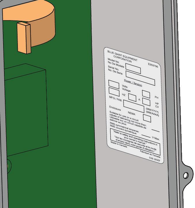
BLUE GENIUS™ TOUCH CONTROL MASTER CONTROL PANELS—OWNER’S MANUAL

5.2 CONTROL SECTIONS: GOLD SERIES III

This section explains the function of each button on the Gold Series III. General operating instructions for all connected dock equipment
appear in the following section.

 1                                                        MENU SCREEN (LCD DISPLAY):
                                                          Displays digital instructions for the operating and troubleshooting of all connected dock equipment.

 2                                                        FORKLIFT TRAFFIC LIGHTS:
                   Do Not Enter
                                                          RED: The connection between the dock and trailer is not yet secure.
                                                          YELLOW: Caution. Restraint is bypassed or ready to end load when flashing.
                         Caution                          GREEN: The connection between the dock and trailer is secure. Also confirms that the leveler is
                                                          released from home and may be engaged to trailer.
                  Enter On Green

 3                                                        CONTROL PANEL KEYPAD:
                          1         2          3          Enables code-based security features such as vehicle restraint bypass.
                          4         5          6
                          77 8                 9

                          *         0          #

          *                                *
 4                                                        DOOR CONTROL:
                         Open
              D
              O
                                               D
                                               O
                                                          OPEN: Opens the overhead door when the door is not programmed to open automatically when
              O
              R                                O
                                               R
                                                          the restraint is engaged.
                         Close

                                                          CLOSE: Lowers the overhead door. Must be held.
                                                          * If Equipped

 5                         5
                                                          RESTRAINT:
                                 Engage

                                                          ENGAGE: Begins the engagement sequence of the restraint arm / hook.
                           (
                           6
                           7
                           5

                                                          RELEASE: Disengages the restraint arm / hook.
                           $
                           ,
                           1     Release
                           7

      †
 6                Deck                     '
                                                          DOCK LEVELER:
          '
          2
          &
                                           2
                                           &
                                           .
                                                   Deck   DECK: Raises the deck from the deployed or parked position.
                                                          LIP: Deploys the deck lip (also parks the deck lip of vertical storing dock levelers).
          .
                                           /
          /                                (
          (       Lip                      9
                                           (

                                                          DOWN: Lowers the deck (vertical storing dock levelers only) or lowers the Door and Dock Guard
          9
          (                                /       Lip
          /                                (
                                           5
          (

                                                          via bypass mode (XDS only).
          5
                  Down

                                                          † VL Vertical Storing Dock Leveler and XDS only.

 7                                                        STOP:
                                 STOP
                                                          Halts or limits the motion of all interlocked equipment and door.

 8                                                        AUDIBLE SPEAKER:
                                                          Brings safety issues to dock attendant's attention.
                                                          Emits sound when "Audible touch" buttons are pressed.

                                                                                                         ISSUE DATE: JULY 15, 2020 REV.1.1 (PART # 038-918E)   9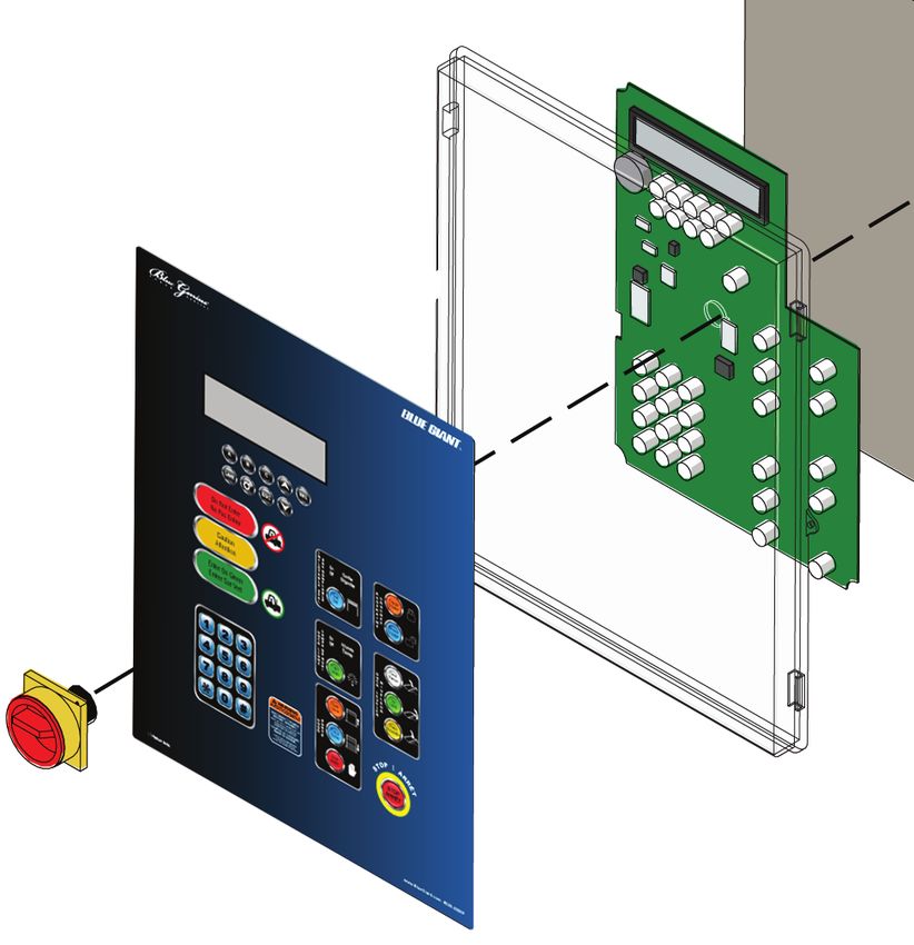
BLUE GENIUS™ TOUCH CONTROL MASTER CONTROL PANELS—OWNER’S MANUAL

6.0 RECOMMENDED SPARE PARTS: GOLD SERIES III

                                                                                                                                               4
                                                                                                                                          3
                         1                                                    2

                         5†                                                  6*                                                           7

 STANDARD OPERATIONAL COMPONENTS                                           STANDARD OPERATIONAL COMPONENTS
  ITEM     PART NO.      DESCRIPTION                          QTY. REQ'D    ITEM       PART NO.       DESCRIPTION                         QTY. REQ'D
         SINGLE PHASE                                                                                 Fuse, 15A, 250V,
                                                                                       026-G100                                               1
                                                                                                      Slow Blow for 1PH, 110-130V
                         Power Board Sub-assembly
          026-PB1115
                         (1PH 115V 50-60HZ)                                                           Fuse, 8A, 250V,
                                                                  1                    026-G101                                               1
                         Power Board Sub-assembly                                                     Slow Blow for 1PH, 208-240V
          026-PB1230
                         (1PH 230V 50-60HZ)                                                           Fuse, 0.5A, 250V
                                                                                       026-G102                                               1
         THREE PHASE                                                                                  Slow Blow for 1 and 3PH, 208-240V

   1                     Power Board Sub-assembly                                                     Fuse, 0.25A, 250V
          026-PB3230                                                                   026-G103                                               1
                         (3PH 230V 50-60HZ)                                                           Slow Blow for 1PH, 208-240V

                         Power Board Sub-assembly                                                     Fuse, 0.75A, 250V
          026-PB3400                                                          7        026-G104                                               1
                         (3PH 400V 50-60HZ)                                                           Slow Blow for 1PH, 110-130V
                                                                  1
                         Power Board Sub-assembly                                                     Fuse, 500mA, 700V,
          026-PB3460                                                                   026-G105                                               1
                         (3PH 460V 50-60HZ)                                                           Fast Blow for 3PH, 380-415V
                         Power Board Sub-assembly                                                     Fuse, 400mA, 700V,
          026-PB3575                                                                   026-G106                                               1
                         (3PH 575V 50-60HZ)                                                           Fast Blow for 3PH, 440-480V
                         Control/Touch Board w/LED and                                                Fuse, 315mA, 700V,
          026-G021-99                                             1                    026-G107                                               1
                         LCD Modules                                                                  Fast Blow for 3PH, 575-600V
   2
         025-G014-V3-M   Transparent Cover Door                   1
                                                                                                      Fuse, 5A, 250V,
                                                                                       026-G123                                               1
              —          Decal, Part # based on Serial #          1                                   Slow Blow for 1PH, 110-130V
   3      026-G025M      Remote I/O-A Board w/ Resistor           1
                         Remote I/O-B Board w/o Resistor
   4      026-G025BM                                              1
                         (for SVR303)
   5     026-G025-99M    Remote I/O-B Board w/ Door Control       1
                         Ribbon Cable, 16 Wire/Pin
   6       026-G030                                               1
                         w/ Connector
                                                                           * Optional † If Equipped

10 ISSUE DATE: JULY 15, 2020 REV.1.1 (PART # 038-918E)
BLUE GENIUS™ TOUCH CONTROL MASTER CONTROL PANELS—OWNER’S MANUAL
7.0 EQUIPMENT COMPONENT ILLUSTRATIONS: GOLD SERIES III
7.1 COMPONENTS AS SHIPPED CHECK LIST: GOLD SERIES III
2 3
1
CONTROL AND
COMPONENTS
4
5
OWNER’S MANUAL
BLUE GENIUS™TOUCH CONTROL
6
MASTER CONTROL PANELS
ACTUAL PRODUCT MAY NOT APPEAR EXACTLY AS SHOWN
WARNING
Do not operate or service this product unless you have
read and fully understand the entire contents of this
manual. Failure to do so may result in property damage,
bodily injury or death.
STARTING FROM MARCH, 2016 / SERIAL # 411892 ISSUE DATE: JULY 15, 2020 REV.1.1 (PART # 038-918E)
ITEM QTY PART NO. DESCRIPTION APPROX. WEIGHT
BGG-X-XXXXX-X
1 1 Dependent on voltage Blue Genius™ Gold Series III Control Panel 10 lb 4.5 kg
See Section 7.2
2 1 025-G010-1 Mounting Tabs with hardware (1 pkg. of 4) — —
E
F
3 1 038-225 Exterior Driver Warning Sign 0.7 lb 0.32 kg
S
P
4 1 032-806 Exterior Driver Traffic Light 1.3 lb 0.6 kg
E
5 1 038-918 F Owner's Manual (this one) — —
S
E
6 1 Dependent on model # F Operation Placard(s) — —
S
ISSUE DATE: JULY 15, 2020 REV.1.1 (PART # 038-918E) 11BLUE GENIUS™ TOUCH CONTROL MASTER CONTROL PANELS—OWNER’S MANUAL
7.2 MECHANICAL ASSEMBLY: GOLD SERIES III
11 Wiring Diagram Enclosed
2
6 7
Fuse Holder 3 4A 4B 4C
9
5
10
3
1
8
12
F2 F1
Fuse Holder 1 4
Fuse Holder 2 F3
COMPLETE CONTROL STATION ASSEMBLY - ITEM 1 (Example BGGFS1115F) ITEM QTY PART NO. DESCRIPTION
6 1 025-G010-1 Mounting Tabs with Hardware (1 pkg. of 4)
ITEM SINGLE PHASE
7 1 026-G030 Ribbon Cable
◊ FUSE QTY PART NO. DESCRIPTION ASSY PART # *
F
F1 A J 1 Power Board F 8 1 038-284E Decal, Serial Plate
026-PB1115 Sub-Assembly † BGGFS1115 S
F2 E 1 (1PH 115V 50-60HZ) S
9 1 038-283ESF Decal, Do Not Drill
F1 1 Power Board F
C 026-PB1230 Sub-Assembly † BGGFS1230 F
F2 1 (1PH 230V 50-60HZ) S 10 1 038-853E Warning Decal
S
THREE PHASE Anti-Static Poly Bag (Wiring Diagram Enclosed)
11 1 026-615-1
◊ FUSE QTY PART NO. DESCRIPTION ASSY PART # * (Serial # required for diagram)
F1 1 Power Board F 12 1 026-G028 Audible Speaker
2
C 026-PB3230 Sub-Assembly † BGGFS3230
F2 1 (3PH 230V 50-60HZ) S F3 1 026-037-1 Fuse, 2.5A, 700V, Fast-Blow 1/4" Glass
F1 1 Power Board F
F 026-PB3400 Sub-Assembly † BGGFS3400 AS PER VOLTAGE - SEE ITEM 1
F2 1 (3PH 400V 50-60HZ) S
ITEM QTY PART NO. DESCRIPTION USE
F1 1 Power Board F
G 026-PB3460 Sub-Assembly † BGGFS3460 Fuse, 15A, 250V LEVELER,
A 1 026-G100
F2 1 (3PH 460V 50-60HZ) S for 1PH,110-130V SVR303
F1 1 Power Board F Fuse, 8A, 250V
B 1 026-G101 TL85
H 026-PB3575 Sub-Assembly † BGGFS3575 for 1PH, 208-240V
F2 1 (3PH 575V 60HZ) S
Fuse, 0.5A, 250V
C 1 026-G102
3 1 025-G010-M Control Box Enclosure (Includes 4C) for 1 and 3PH, 208-240V
Transparent Cover Door (4C) and Touch Fuse, 0.25A, 250V
D 1 026-G103
4 1 025-G014-V3-M for 1PH, 208-240V
Control Board (4A) (Serial # Required)
Fuse, 0.75A, 250V,
4A 1 026-G021-M Touch Control Board (Serial # Required) E 1 026-G104
for 1PH, 110-130V
4B 5 025-062 Cable Tie Mount Fuse, 500mA, 700V
F 1 026-G105
for 3PH, 380-415V
4C 1 025-G014 Transparent Cover Door
Fuse, 400mA, 700V
G 1 026-G106
F for 3PH, 440-480V
5 1 038-XXXE Face Decal (Dependent on Configuration)
S Fuse, 315mA, 700V
H 1 026-G107
for 3PH, 575-600V
* Language on decal: F = English / French S = English / Spanish Fuse, 5A, 250V
J 1 026-G123 HVR303
for 1PH 110-130V
◊ Location on Power Board † Includes Fuses ‡ 115 Volt Control Box Shown
12 ISSUE DATE: JULY 15, 2020 REV.1.1 (PART # 038-918E)BLUE GENIUS™ TOUCH CONTROL MASTER CONTROL PANELS—OWNER’S MANUAL
7.3 GENERAL DIMENSIONS: GOLD SERIES III
6 5/32" 5 13/32"
(156mm) Ø 1/4" (137mm)
Ø 3/16" Slot typ.
typ.
11 29/32" 12 17/32"
(302mm) 11 9/32" 10 19/32" 13"
(318mm)
(287mm) (269mm) (330mm)
7 15/32"
(190mm)
8 1/32" 5 27/32"
(204mm) (148mm)
R= 7 15/32"
(190mm)
ISSUE DATE: JULY 15, 2020 REV.1.1 (PART # 038-918E) 13BLUE GENIUS™ TOUCH CONTROL MASTER CONTROL PANELS—OWNER’S MANUAL
8.0 CONTROL PANEL OPERATION: PLATINUM SERIES
Controls combinations of all supported dock equipment: one individual vehicle restraint, dock leveler, door, inflatable seal, and dock
light. Also equipped with touch buttons, inside forklift operator traffic lights, operator menu screen, and keypad for coded features.
R
C o n t r o l
ON
1 5
Menu Screen Rotary Disconnect
(LCD Display)
Menu Choice Scroll “UP”
Buttons
A B C SEL Select
2
Change Language Scroll “DOWN”
ESC
Button
Escape
Setup ,
1 Restraint “ENGAGE”
(Root Menu System) ) On 5
Do Not Enter /
$ Off (
6
Engage
(Raise / Lock Restraint)
7
6
7
3
$
% 5
Red Light / $
Restraint “RELEASE”
( ,
Seal 1 Release
(Do Not Enter) 6
7
Caution (
$ (Lower / Unlock
/
Restraint) / Override
Yellow Light Release
(Proceed with Caution)
Enter On Green ' On
Deck
7
2 Off Inflatable Seal
& '
. 2
Green Light / &
8
, .
*
(Enter on Green) + Light /
Lip
7 (
9
Dock Leveler
(
/ (Raise/Lower Deck/Lip)
4
(
1 2 3
5
Down
Control Station Keypad
(Override, Security, Open
9
Features) 4 5 6 Dock Light
10
'
77 8 9
2 Close
2
5 Door
WARNING
(Open/Close/Stop)
* 0 #
DISCONNECT POWER
STOP STOP
11
BEFORE OPENING.
READ AND FULLY
UNDERSTAND THE OWNER’S
MANUAL BEFORE OPERATING
THIS PRODUCT.
“STOP”
Platinum Series
Platinum Series
www.BlueGiant.com #038-898EF
www.BlueGiant.com
12
Audible Speaker
NOTE: Typical decal shown, actual decal is bilingual.
8.1 BUTTON FUNCTION: PLATINUM SERIES
5R Engage
When touching any of the function buttons or keypad, use the pad (E Engager
of the finger. The control panel’s unique touch sensors detect the 6S
7T
proximity of the dock operator’s finger. Audible touch buttons and 5R Audible touch
keypad on the control panel provide instant sound feedback to
$
,
A
1I Release
user input. 7N
T
14 ISSUE DATE: JULY 15, 2020 REV.1.1 (PART # 038-918E)BLUE GENIUS™ TOUCH CONTROL MASTER CONTROL PANELS—OWNER’S MANUAL
8.2 CONTROL SECTIONS: PLATINUM SERIES
This section explains the function of each button on the Platinum Series. General operating instructions for all connected dock equipment
appear in the following section.
1 MENU SCREEN (LCD DISPLAY):
Displays digital instructions for the operating and troubleshooting of all connected dock
equipment.
2 LANGUAGE:
Changes the LCD display language to English, French, or Spanish.
3 LED CONTROL PANEL LIGHTS:
Do Not Enter RED: Do Not Enter: the connection between the dock and trailer is not yet secure.
YELLOW: Caution. Restraint is bypassed or ready to end load when flashing.
Caution
GREEN: Enter: the connection between the dock and trailer is secure.
Enter On Green
4 CONTROL STATION KEYPAD:
1 2 3 Enables code-based security features such as vehicle restraint bypass.
4 5 6
77 8 9
* 0 #
5 ROTARY DISCONNECT:
ON
ON: Locks the control panel enclosure and provides power to the unit.
OFF: Unlocks the control panel enclosure and cuts power to the unit.
6 RESTRAINT:
5
ENGAGE: Begins the engagement sequence of the restraint arm / hook.
( Engage
6
7
RELEASE: Disengages the restraint arm / hook.
5
$
,
1 Release
7
7
,
1
) On
INFLATABLE SEAL:
Activates and deactivates the inflatable seal when the seal is not in automatic mode.
/
$ Off
7
$
%
/
(
Seal
6 Sas
(
$
/
DOCK LEVELER:
8 Deck
'
2
DECK: Raises the deck from the deployed or parked position.
&
.
/
Lip
LIP: Deploys the deck lip (also parks the deck lip of vertical storing dock levelers).
DOWN: Lowers the deck (vertical storing dock levelers only) or lowers the Door and Dock
(
9
(
/
Guard via bypass mode (XDS only).
(
5
Down
ISSUE DATE: JULY 15, 2020 REV.1.1 (PART # 038-918E) 15BLUE GENIUS™ TOUCH CONTROL MASTER CONTROL PANELS—OWNER’S MANUAL
8.2 CONTROL SECTIONS: PLATINUM SERIES CONT'D.
DOCK LIGHT:
9 On
Activates and deactivates the dock light when the light is not in automatic mode.
'
2 Off
&
.
/
,
*
+ Light
7
10 DOOR:
Open
OPEN: Opens the overhead door when the door is not programmed to open automatically when
'
the restraint is engaged.
2
CLOSE: Lowers the overhead door. Must be held.
2 Close
5
STOP: Stops the door in mid-motion.
STOP
11 STOP:
STOP
Halts or limits the motion of all interlocked equipment and door.
12 AUDIBLE SPEAKER:
Brings safety issues to dock attendant's attention.
Emits sound when "Audible touch" buttons are pressed.
16 ISSUE DATE: JULY 15, 2020 REV.1.1 (PART # 038-918E)BLUE GENIUS™ TOUCH CONTROL MASTER CONTROL PANELS—OWNER’S MANUAL
9.0 RECOMMENDED SPARE PARTS: PLATINUM SERIES
1 2 3
4 5* 6*
4A
7 8 9 10*
STANDARD OPERATIONAL COMPONENTS STANDARD OPERATIONAL COMPONENTS
ITEM PART NO. DESCRIPTION QTY REQ’D ITEM PART NO. DESCRIPTION QTY REQ’D
1 026-CB-BGP Control Board Assembly 1 6 028-586 Receptacle GFI 1
Relay Board Assembly 028-605 4 A Circuit Breaker (Shown)
2 026-XXXXXX-BGP 1
See Section 10.2 7 1
026-746 15 A Circuit Breaker
Power Board Assembly
3 026-PBXXX-BGP 1
See Section 10.2 8 See Section 15.2 Fuse Control —
4 026-IO-BGP PCB, BGP, I/O 1 9 See Section 15.2 Fuse Power —
5 028-588 Disconnect Switch 1 10 026-G030 Ribbon Cable (16C) 1
* Optional
ISSUE DATE: JULY 15, 2020 REV.1.1 (PART # 038-918E) 17BLUE GENIUS™ TOUCH CONTROL MASTER CONTROL PANELS—OWNER’S MANUAL
10.0 EQUIPMENT COMPONENT ILLUSTRATIONS: PLATINUM SERIES
10.1 COMPONENTS AS SHIPPED CHECK LIST: PLATINUM SERIES
2 3
1
CONTROL AND
COMPONENTS
4
5
OWNER’S MANUAL
BLUE GENIUS™TOUCH CONTROL
6
MASTER CONTROL PANELS
ACTUAL PRODUCT MAY NOT APPEAR EXACTLY AS SHOWN
WARNING
Do not operate or service this product unless you have
read and fully understand the entire contents of this
manual. Failure to do so may result in property damage,
bodily injury or death.
STARTING FROM MARCH, 2016 / SERIAL # 411892 ISSUE DATE: JULY 15, 2020 REV.1.1 (PART # 038-918E)
ITEM QTY PART NO. DESCRIPTION APPROX. WEIGHT
BGP-4-XXXXX-X
1 1 Dependent on voltage Blue Genius™ Platinum Series Control Panel 25 - 35 lb 11 - 16 kg
See Section 10.2
2 1 025-G012-1 Mounting Tabs with Hardware (1 pkg. of 4) — —
E
F
3 1 038-225 Exterior Driver Warning Sign 0.7 lb 0.32 kg
S
P
4 1 032-806 Exterior Driver Traffic Light 1.3 lb 0.6 kg
E
5 1 038-918 F Owner's Manual (this one) — —
S
E
6 1 Dependent on model # F Operation Placard(s) — —
S
18 ISSUE DATE: JULY 15, 2020 REV.1.1 (PART # 038-918E)BLUE GENIUS™ TOUCH CONTROL MASTER CONTROL PANELS—OWNER’S MANUAL
10.2 MECHANICAL ASSEMBLY: PLATINUM SERIES
23 Wiring Diagram Enclosed
5 21 18
2 4
8
13 9 25 26 22
F20 3 7 6 17 24 14 15
F21
11 10 12 F22
F23
19
F4
16
F3 F5
20
1
F1 F2
ISSUE DATE: JULY 15, 2020 REV.1.1 (PART # 038-918E) 19BLUE GENIUS™ TOUCH CONTROL MASTER CONTROL PANELS—OWNER’S MANUAL
10.2 MECHANICAL ASSEMBLY: PLATINUM SERIES CONT'D.
COMPLETE CONTROL STATION ASSEMBLY - ITEM 1 (Example BGP-4-460-115F) ITEM QTY PART NO. DESCRIPTION
5 1 025-G012-A Enclosure
ITEM ◊ FUSE QTY PART NO. DESCRIPTION ASSY PART # *
SINGLE PHASE - POWER BOARD 6 1 025-G030-A Assembly, Plate, Backing
F1 B 2 Power Board † F 025-G035 Assembly, DIN Rail, BGP(4A)
026-PB115-BGP BGP-4-115 7 1
F2 C 3 Assembly, 115V, 1PH S 025-G036 Assembly, DIN Rail, BGP (15A)
F3
F4 D 2 Power Board † F 8 1 028-592 Shaft, Disconnect
026-PB230-BGP BGP-4-230-115
F5 C 3 Assembly, 230V, 1PH S
9 1 025-G031-A Divider Plate
THREE PHASE - POWER BOARD
F
D 2 F 10 1 038-400E Decal, Blue Genius™ Platinum Series *
Power Board † S
026-PB230-BGP BGP-4-230-115
C 3 Assembly, 230V, 3PH S
11 1 028-590 Rotary Disconnect Handle
F
F 2 BGP-4-460-115 12 1 026-IO-BGP PCB, BGP, I/O
Power Board † S
2 026-PB400-BGP 13 1 026-CB-BGP Control Board Assembly
Assembly, 400V, 3PH F
C 3 BGP-4-460-230
F1 S 14 1 028-586 GFI Receptacle 120V (4A STD. 15A OPT.)
F2 F 15 1 028-587 Receptacle Cover
F3 G 2 BGP-4-460-115
F4 Power Board † S 16 1 026-G030 Ribbon Cable
026-PB460-BGP
F5 Assembly, 460V, 3PH F
C 3 BGP-4-460-230 17 1 026-G028 Audible Speaker
S
18 4 025-G012-1 Mounting Tabs
F
E 2 BGP-4-575-115
19 1 026-G048-A Cable Assembly, BGP, I/O-RLY, 28.5," 8Pins
Power Board † S
026-PB575-BGP
Assembly, 575V, 3PH F 20 1 026-G049-A Cable Assembly, BGP, PSU-I/O, 13.5," 10Pins
C 3 BGP-4-575-230
S
21 1 038-283ESF Decal, Do Not Drill
SINGLE PHASE - RELAY BOARD
F20 F
Relay Board F 22 1 038-853E Warning Decal *
F21 S
J 4 026-RB1230-BGP Assembly, BGP-4-115
F22
115-220V, 1PH S Anti-Static Poly Bag (Wiring Diagram
F23
23 1 026-615-1
Enclosed - Serial # req'd for diagram)
THREE PHASE - RELAY BOARD
F
Relay Board F 24 1 038-284E Decal, Serial Plate *
J 4 026-RB3230-BGP BGP-4-230-115 S
Assembly 220V, 3PH S
3 F 25 2 025-G032 Hinge Kit, DSE Control Box
BGP-4-460-115
S 26 1 030-907 Enclosure Frame, BGP
F20
F21 F
BGP-4-460-230
F22 Relay Board S
F23 J 4 026-RB3575-BGP Assembly AS PER VOLTAGE - SEE ITEM 1
400-575V, 3PH F
BGP-4-575-115 ITEM QTY PART NO. DESCRIPTION USE
S
F
Fuse, 8A, 250V
B 1 026-G101 TL85
BGP-4-575-230 for 1PH, 208-240V
S
Fuse, 0.5A, 250V
Transformer, C 1 026-G102
026-381 BGP-4-230-115 for 1 and 3PH, 208-240V
1000VA, 240V-120V
Transformer, D 1 026-237-1 Fuse, 2.5A, 250V, Fast Blow
026-380 BGP-4-460-115
1000VA, 480V-120V
Transformer, Fuse, 0.75A, 250V,
026-382 BGP-4-460-230 E 1 026-G104
1000VA, 480V-240V
for 1PH, 110-130V
Transformer,
026-383 BGP-4-575-115 Fuse, 500mA, 700V
1000VA, 600V-120V F 1 026-G105
for 3PH, 380-415V
4 1 Transformer,
026-384 BGP-4-575-230
1000VA, 600V-240V Fuse, 400mA, 700V
G 1 026-G106
Transformer, for 3PH, 440-480V
BGP-4-460-115
2000VA, 480V - 120V
Fuse, 315mA, 700V
Transformer, H 1 026-G107
BGP-4-460-230 for 3PH, 575-600V
2000VA, 480V - 240V
026-385
Transformer, Fuse, 5A, 250V
BGP-4-575-115 J 1 026-G123 HVR303
2000VA, 600V - 120V for 1PH 110-130V
Transformer,
BGP-4-575-230 * Language on decal: F = English / French S = English / Spanish
2000VA, 600V - 240V
◊ Location on Power Board † Includes Fuses
20 ISSUE DATE: JULY 15, 2020 REV.1.1 (PART # 038-918E)BLUE GENIUS™ TOUCH CONTROL MASTER CONTROL PANELS—OWNER’S MANUAL
10.3 GENERAL DIMENSIONS: PLATINUM SERIES
8 15/16"
(227mm)
7 13/16"
(199mm)
T o u c
e
h C o n t r o l
R
A B C SEL
ESC
19 5/8" 21 1/16"
(498mm) (535mm)
1 2 3
4 5 6
7 8 9
* 0 # STOP
ARRÊT
15 11/16" 4 5/8"
(398mm) (117mm)
9 7/16"
(239mm)
R = 15 11/16"
(398mm) 23 1/2"
(594mm)
3 3/4"
(96mm) 24 1/16" 2"
(611mm) (52mm)
ISSUE DATE: JULY 15, 2020 REV.1.1 (PART # 038-918E) 21BLUE GENIUS™ TOUCH CONTROL MASTER CONTROL PANELS—OWNER’S MANUAL
11.0 DECAL IDENTIFICATION AND LOCATION: GOLD SERIES III AND PLATINUM SERIES
WARNING
1. Do not operate this dock equipment without training and authorization.
2. Read, understand, and follow these instructions and the warnings /
instructions in the Owner’s Manual.
1 3.
-
-
Prior to using this dock equipment:
Ensure that all snow, debris, and obstructions have been cleared
away from the path of operation.
Ensure that all personnel in the vicinity are aware that the equipment
will be in use.
- Operate the equipment through one full cycle to verify that all
components are functioning properly. If damage is observed or the
equipment malfunctions, notify maintenance personnel immediately
and do not use until required repairs have been made.
4. Verify that the truck has been properly chocked and / or restrained
prior to loading or unloading.
5. Verify that the dock leveler lip overlaps the trailer bed by a MINIMUM
of 4” (102mm).
6. Keep hands and feet clear of all pinch points.
7. Do not exceed the rated capacity as indicated on the dock leveler
serial plate.
8. Do not use the dock leveler if the trailer bed exceeds the leveler’s
service range.
5
9. If an interior and exterior lights communication package has been
installed, load and unload ONLY when the interior light is GREEN.
10. Do not leave equipment or cargo unattended on the dock leveler.
11. If maintenance or service is required:
- Only authorized service personnel shall perform all repairs and
maintenance steps.
1
- Follow approved lockout / tagout procedures.
APPLIES TO ALL STANDALONE DOCK LEVELERS, VEHICLE RESTRAINTS,
AND DOCK EQUIPMENT COMBOS
Failure to follow the instructions above could result in death and / or
serious injury.
AVERTISSEMENT
2 1. Ne pas utiliser cet équipement sans la formation et l’autorisation
nécessaire.
2. Lire, comprendre, et suivre ces instructions et les avertissements /
instructions dans le Guide d’Utilisation.
3. Avant d’utiliser cet équipement:
- S’assurer que toute la neige, les débris, et les obstructions soient
dégagés de la voie d’opération.
- S’assurer que tout le personnel aux alentours sachent que
l’équipement sera en service.
- Faire cycler l’équipement complètement pour vérifier que tous les
composants fonctionnent bien. S’il y a de l’endommagement ou
l’équipement est défectueux, aviser le personnel d’entretien
immédiatement et ne pas utiliser l’unité avant qu’elle soit réparée.
4. Vérifier que le camion soit bien calé et/ou retenu avant de charger ou
décharger.
5. Vérifier que la lèvre du niveleur de quai chevauche le plateau du
camion par AU MOINS 4” (102mm).
6. Garder les mains et les pieds loin de tous les points de pivotement.
7. Ne pas dépasser la capacité nominale indiquée sur la plaque
signalétique du niveleur de quai.
8. Ne pas utiliser le niveleur si le plateau du camion dépasse la portée
de service du niveleur.
9. Si un système de feux de communications intérieur et extérieur est
installé, charger et décharger SEULEMENT lorsque la lumière
intérieure est VERTE.
10. Ne pas laisser l’équipement ou la charge sans surveillance sur le
niveleur de quai.
11. Si de l’entretien ou du service est requis:
- Seul du personnel de service autorisé doit effectuer les réparations et
4
l’entretien.
- Suivre les procédures de verrouillage et d’étiquetage approuvées.
1 2
S’APPLIQUE À TOUS NIVELEURS DE QUAI INDÉPENDANTS, SYSTÈMES
DE RETENUE, ET COMBOS ÉQUIPEMENTS DE QUAI.
Défaut de suivre les instructions ci-dessus peut causer des blessures
graves et/ou la mort. 038-853EF
ATTACHED TO DIVIDER PLATE
IN PLATINUM SERIES
6
2
BLUE GIANT EQUIPMENT E353795
CORPORATION
Model No.
No De Modele
Serial No.
3
No. De Serie
Power / Tension
Volts PH
Voltage
HP
HZ A
CV GOLD SERIES III
MFG / FAB. (MM/YYYY)
(MM/AAAA)
Enclosure NEMA
Suitable for use on a circuit
cabale of delivering not more than:
Utilisable sur un circuit capable de
delivrer au plus:
ITEM QTY PART NO. * DESCRIPTION RMS symmetrical amperes:
RMS courant symetrique:
V Max.
F “Refer to safety and operating instructions in
1 1 038-283E Decal - Do Not Drill your owner’s manual.”
“Voir les consignes de securite et le mode
S d’emploi dans votre guide d’utilisation.”
Made in Canada Fabrique au Canada
F 038-285EF
2 1 038-853E Decal - Warning
S
F Decal - Serial Plate
3 1 038-285E
S (Located inside control box enclosure)
F 3
4 1 038-296E Decal - Warning Interior Control Box
S
Dependent on F
5 1 Decal - Blue Genius Gold Series III PLATINUM SERIES
Model S
F
6 1 038-400E Decal - Blue Genius Platinum Series
S
22 ISSUE DATE: JULY 15, 2020 REV.1.1 (PART # 038-918E)BLUE GENIUS™ TOUCH CONTROL MASTER CONTROL PANELS—OWNER’S MANUAL
12.0 STOP PROCEDURE: GOLD SERIES III AND PLATINUM SERIES
If dock equipment needs to be stopped immediately, the operator can use the 'STOP' button. Touching the 'STOP' button during operation
allows the operator to halt or limit equipment motion in the event of a potential emergency.
When in STOP mode:
• DO NOT go under the dock leveler
• DO NOT walk or drive on lip or deck
• DO NOT leave truck or material sitting on the leveler
1) Touch the 'STOP' button. The control panel light instantly
changes to flashing RED and the exterior traffic light will turn RED.
The audible alarm will beep until stop mode is exited.
To silence the audible alarm, touch the 'STOP' button a second
time as acknowledgement that stop has been activated. STOP
2) "SYSTEM STOPPED, To Continue...Touch and Hold ESC Key"
will appear on LCD screen.
MENU DISPLAY
SCREEN
Verify surroundings and corrections before exiting stop mode.
3) To exit stop mode, touch the 'ESC' button. "Please Wait..." will
appear on LCD screen.
The system will reset with lights and operation as required. ESC
ESC
ISSUE DATE: JULY 15, 2020 REV.1.1 (PART # 038-918E) 23BLUE GENIUS™ TOUCH CONTROL MASTER CONTROL PANELS—OWNER’S MANUAL
13.0 OPERATING INSTRUCTIONS: GOLD SERIES III AND PLATINUM SERIES
Operating instructions are not always chronological. Perform steps as necessary. The following steps apply to pit-style dock levelers only.
BEFORE THE TRUCK ENTERS THE DRIVEWAY: ENGAGING THE VEHICLE RESTRAINT:
EXTERIOR TRAFFIC INSIDE COMMUNICATION
LIGHT STATUS LIGHTS & CONTROL PANEL Do Not Enter RR
Engage
EE
SS
TT
Caution RR
Do Not Enter AA
II
NN Release
TT
Caution Enter on Green
Enter on Green
A B
Before the truck enters the driveway, the exterior traffic light will be GREEN Touch the 'Engage' button to activate vehicle restraint. Exterior traffic light
and the control panel light will be RED. The screen will read "Blue Genius will change to RED. Screen will read "Restraint Engaging." Once the ICC bar
Ready." The truck may now enter the driveway. This sequence also indicates is secured, the message will change to "Restraint is Engaged" followed by
that it is safe for the truck to leave at the end of loading / unloading. "Dock Leveler Restored" and "Ready to Raise Deck." If a warning message
appears on the screen, see Section 14.0 "Engaging the Override Feature:
Gold Series III and Platinum Series."
DOOR: DEPLOYING DOCK (DECK BUTTON ONLY):
'
Do Not Enter Do Not Enter 2 Deck
D & 1 Deck
.D , Rampe
O O9
O /C (
Caution R Caution ( /
9K (
(L 8
Lip
/ 5 Lip
(E Lèvre
Enter on Green Enter on Green 5V
E
L
E
R
Down
"Door" button appearance may vary
depending on model.
C D
Press the 'OPEN' button to raise the overhead door when the door is Touch the 'Deck' button. Screen will read "Deck Raising." Hold until lip
not in automatic mode. Screen will read "Door is Opening." deploys. Release button. Screen will read "Deck Moving." Dock leveler
and lip will descend onto the truck bed. Screen will read "Deck Deployed."
Control panel light will turn GREEN. If deploying below level, see Section
13.1 "Alternative Methods of Operation: Gold Series III and Platinum Series."
DEPLOYING DOCK (DECK AND LIP BUTTON): RESTRAINT AND LEVELER DEPLOYED:
Do Not Enter ' Do Not Enter
2 Deck
& 1 Deck
D ,
. Rampe
O9
Caution C(
/ Caution
( /
K (
9
(
L 8 Lip
/ 5
E Lip
( Lèvre
Enter on Green V
5 Enter on Green
E
L
E
"Lip" and/or "Down" button(s) only R
Down
appear on specific control panels.
Depending on configuration, yours may
not include one or both of these buttons.
E F Step end state
Touch and hold the 'Deck' button. Screen will read "Deck Raising." When Restraint and leveler deployed correctly. Perform loading and unloading.
the lip has cleared the lip keepers or trailer, release the "Deck" button and
touch and hold the 'Lip' button. Screen will read "Lip Moving." Release
button. Screen reads "Deck Moving." The leveler and lip will descend to
truck bed, message will change to "Deck Deployed". Control panel light
will turn GREEN.
24 ISSUE DATE: JULY 15, 2020 REV.1.1 (PART # 038-918E)BLUE GENIUS™ TOUCH CONTROL MASTER CONTROL PANELS—OWNER’S MANUAL
13.0 OPERATING INSTRUCTIONS: GOLD SERIES III AND PLATINUM SERIES CONT'D.
PERFORM LOADING AND UNLOADING
STORING THE DOCK LEVELER: RELEASING THE VEHICLE RESTRAINT:
*
Do Not Enter '
Do Not Enter
2 Deck RR Engage
& 1 Deck EE Engage
.D , Rampe
9 SS
O TT
/ (
Caution (C/ Caution RR
9K( AA
( 8 II
/L 5 Lip
Lip NN Release
(E Lèvre Release
Enter on Green 5V Enter on Green TT
E
L
E
R
Down
G H
Touch and hold the 'Deck' button. Control panel light will turn RED. The Touch the 'Release' button. Screen will read "Restraint Releasing."
deck will raise and lip will retract. When the lip has fully retracted, release When the restraint is in the home position, message will change to
the 'Deck' button. Screen will read "Deck Moving" and the deck will lower "Blue Genius Ready."
to stored position with the lip in the lip keepers. Message will change to
"Dock Leveler Restored" followed by "Ready to Release" (refers to vehicle * Traffic light will turn GREEN after the restraint is lowered.
restraint).
NOTE: Following this step, press the 'Close' button on the door controls
(see Section 13.0 "Operating Instructions: Gold Series III and Platinum
Series", Step C) to lower the overhead door. Screen will read "Door is
Closing."
13.1 ALTERNATIVE METHODS OF OPERATION: GOLD SERIES III AND PLATINUM SERIES
BELOW LEVEL END LOADING: RETURNING TO NORMAL LIP ON LOAD BED OPERATION:
' '
Do Not Enter 2 Do Not Enter 2 Deck
Deck & 1
& 1 Deck Deck
Rampe
. , Rampe . ,
9 9
/ ( / (
Caution ( / Caution ( /
9 ( 9 (
( 8 ( 8
Lip Lip
/ 5 Lip / 5 Lip
( Lèvre ( Lèvre
Enter on Green 5 Enter on Green 5
Down Down
I J
Touch the 'Deck' button. Screen will read "Deck Raising." Hold until lip Touch and hold the 'Deck' button until the dock is high enough for the
partially extends. Release 'Deck' button. Screen will read "Deck Moving." lip to deploy safely onto the load bed. Return to Step F of Section 13.0
The dock leveler and lip will descend. The lip will hang in pendent position "Operating Instructions: Gold Series III and Platinum Series."
between dock face and trailer. Screen will read "Deck Deployed." Control
panel light will turn GREEN.
ISSUE DATE: JULY 15, 2020 REV.1.1 (PART # 038-918E) 25BLUE GENIUS™ TOUCH CONTROL MASTER CONTROL PANELS—OWNER’S MANUAL
14.0 ENGAGING THE OVERRIDE FEATURE: GOLD SERIES III AND PLATINUM SERIES
Should it be necessary to bypass the vehicle restraint function (i.e. the truck has an outdated, damaged, or missing ICC bar), a system-
approved override code may be entered via the Blue Genius™ touch keypad. This code can be used whether or not the dock leveler is
interlocked with the Blue Genius.™ Ensure that the vehicle is manually chocked before loading and unloading begins.
NOTE: If a visual inspection confirms that the ICC bar is missing or too damaged to be secured, bypass Step 1 in the instructions below
and go directly to Step 2, which explains how to enter the Override Code.
1. During "Engaging the Vehicle Restraint" (see Section 13.0
MENU DISPLAY
"Operating Instructions: Gold Series III and Platinum Series," SCREEN
Step B), the LCD screen may read "ICC Bar Not in Range." This
message indicates that a vehicle's ICC bar is absent or cannot be
engaged. Determine whether the vehicle needs to be realigned
or if wheel chocks are necessary. Press "SEL" to continue.
Wheel chock
2A. Press the * key on the keypad. The LCD screen will read
‘Enter Code *_ _ _’.
1 2 3
Do Not Enter
Enter the supervisor code (default factory set code is '247').
NOTE: The default code can be changed. Please call your
Caution
4 5 6
Blue Giant representative for further information.
Enter on Green 77 8 9
* 0 #
26 ISSUE DATE: JULY 15, 2020 REV.1.1 (PART # 038-918E)BLUE GENIUS™ TOUCH CONTROL MASTER CONTROL PANELS—OWNER’S MANUAL
14.0 ENGAGING THE OVERRIDE FEATURE: GOLD SERIES III AND PLATINUM SERIES CONT'D.
Continue operation of overhead door, dock leveler, and vehicle restraint as outlined in Section 13.0 / 13.1 "Operating Instructions: Gold
Series III and Platinum Series / Alternative Methods of Operation: Gold Series III and Platinum Series." The following indicators will appear:
2B. The LCD screen will read ‘Dock Leveler Restored’ and then
"Ready to Deploy Deck," followed by "Restraint Is Bypassed."
2C. Once the deck is deployed and the home sensor becomes
inactive, the control panel light will turn GREEN while flashing
YELLOW. This indicates that the vehicle restraint is not
engaged. Do Not Enter
Caution
Enter on Green
14.1 RELEASING THE OVERRIDE FEATURE: GOLD SERIES III AND PLATINUM SERIES
1. Store the dock leveler. (NOTE: Override is still active when
dock leveler and vehicle restraint are in the parked position).
The control panel light will turn RED. Do Not Enter
RR Engage
EE Engage
SS
Touch the ‘Release’ button on the control panel to release the TT
Caution RR
override. The control panel will verify that the vehicle restraint AA
II
Release
has been lowered to the home position. The LCD screen NN
TT
Enter on Green
will read "Blue Genius Ready" (see Section 13.0 "Operating
Instructions: Gold Series III and Platinum Series," Step H)
The exterior traffic light will turn GREEN, advising the truck Light will only turn GREEN
driver that it is safe to depart once the wheel chocks are at the end of this step.
removed.
ISSUE DATE: JULY 15, 2020 REV.1.1 (PART # 038-918E) 27BLUE GENIUS™ TOUCH CONTROL MASTER CONTROL PANELS—OWNER’S MANUAL
15.0 EXTERIOR TRAFFIC LIGHT / MIRROR SIGN IMAGE: GOLD SERIES III AND PLATINUM SERIES
The LED traffic lights and mirror image drive warning sign improve loading dock safety.
¼"
(6.35 mm)
5" (127 mm)
11.75"
4 3/8" (111 mm) (298 mm)
Ø 5/16" x 4
(254 mm)
(238 mm)
(483 mm)
9 3/8"
10"
19"
Exterior driver traffic light, part # 032-806. Exterior driver warning sign, part # 038-225.
(French 038-225F / Spanish 038-225S / Portuguese 038-225P)
NOTE: Mount to a flat surface. DO NOT deform light housing
with irregular wall surface.
28 ISSUE DATE: JULY 15, 2020 REV.1.1 (PART # 038-918E)BLUE GENIUS™ TOUCH CONTROL MASTER CONTROL PANELS—OWNER’S MANUAL
16.0 CONTROL PANEL LCD MESSAGES: GOLD SERIES III AND PLATINUM SERIES
WARNING
Do not attempt to install, make repairs or adjustments. Only a trained and authorized service technician should perform the
installation process. Contact your local dealer or distributor for assistance.
MESSAGE EXPLANATION
1. IPS shaft not secured by set screw, tighten set screw making sure the IPS green LED light
'Fault 31'
is lit with the restraint arm in its lowered position.
NOTE: the set screw does not tighten down on the flat of the IPS shaft.
IPS sensor value too low
2. IPS not programmed. See set-up procedure.
During self test mode the
following message appear: 1. Faulty wiring, communication cable not connected or damaged.
'Remote I/O Bad' 2. Circuit board faulty.
'Positioner Bad'
1. Restraint interlock sensor (home/lip) is in-active, out of range.
2. Restraint interlock sensor (home/lip) is not connected.
'Please restore Dock Leveler'
3. Faulty wiring.
4. Dock not in stored/home position.
1. Restraint arm went up and did not find ICC bar in preset range.
'ICC Bar not in Range'
2. IPS not programmed.
1. Faulty wiring, check for loose or broken communication cable wire(s).
'Fault 10'
2. Noise interference, check routing of communication from Blue Genius™ controls to remote
Communication error
devices.
'Restraint Arm Blocked'
Followed by: 1. Restraint arm failed to lower all the way down. Check for debris.
'Restore Restraint, press 2. Faulty IPS board or switches.
'SEL' to continue, Blue 3. Faulty wiring.
Genius™ Warning' (repeats)
'Restraint is Engaged'
Followed by: 'Dock Leveler
1. The 'Engage' button has been touched and vehicle restraint is in locked position.
Restored', 'Ready to Deploy
Deck'. (repeats)
During self test mode the 1. Faulty wiring, check communication cable wires for loose connections.
following message appears: 2. Remote I/O is faulty, replace.
'Remote I/O Bad' 3. Blue Genius™ power board is faulty, replace.
During self test mode the 1. Faulty wiring, check communication cable wires for loose connections.
following message appears: 2. IPS board is faulty, replace.
'Positioner Bad' 3. Blue Genius™ power board is faulty, replace.
17.0 WIRING DIAGRAMS: GOLD SERIES III AND PLATINUM SERIES
NOTICE
The following wiring diagrams are sample configurations only. Wiring diagrams specific to your needs will be provided inside the control panel
and/or as part of your submittal package.
ISSUE DATE: JULY 15, 2020 REV.1.1 (PART # 038-918E) 29DRAIN
(Twist & Insulate)
SVR303 INTELLIGENT COMMUNICATION CABLE DRAIN
POSITION SENSOR COMMUNICATION CABLE
REMOTE I/O-B DRAIN
(Twist & Insulate)
A DOOR CONTROL (OPT.) DRAIN
B BLUE WHITE
COM DECK 17 COM A 01 01 WHITE
BLACK GREEN A COMM.
+24 HOME 18 INPUT 1 B 02 GREEN
BLACK B 02 TERMINAL BLOCK IN
SENSOR BROWN COM
19 +24 03 BLACK BG CONTROL PANEL
RED COM 03
20 COM +24 04 RED WHITE
+24 04 01 A
21 INPUT 2 GREEN 02 B
22 +24 OVERHEAD BLACK,DRAIN
GREY 03 COM
23 COM OUTPUT 1 05 PHOTOELECTRIC RED
LOCK 04 +24
BROWN SENSOR, TOP BLUE
24 INPUT 3 +24 06 SOLENOID
GREY (OPTIONAL) BROWN 05 I1
25 +24 OUTPUT 2 07 ARM
BROWN BLACK 06 I2
26 COM +24 08 SOLENOID
07 N/C
27 INPUT 4 OUTPUT 3 09
AUDIBLE 08 N/O
28 +24 +24 10
GREY EXTERIOR ALARM 09 RC
29 COM OUTPUT 4 11 LIP TRAFFIC RED
BROWN 10 +
30 INPUT 5 +24 12 SOLENOID LIGHTS BLACK
11 -
31 +24 OUTPUT 5 13 RED
12 RED
32 COM +24 14 GREEN
13 GREEN
33 INPUT 6 OUTPUT 6 15 BLACK
14 COM
34 +24 +24 16
30 ISSUE DATE: JULY 15, 2020 REV.1.1 (PART # 038-918E)
BG CONTROL PANEL CONNECTIONS
* MC’S ARE INTERNALLY CONNECTED
MOTOR 1 MOTOR 2 GROUND POWER
FUSED DISCONNECT
BY OTHERS
(115V, 1PH)
M1 MC M2 MC L N
MOTOR * *
MOTOR
JUNCTION BOX L N
BLACK M1
F1
WHITE MC
CABLE BY OTHERS
SEE
GREEN GND NOTES
CABLE BY OTHERS
NOTICE
BLUE GENIUS™ TOUCH CONTROL MASTER CONTROL PANELS—OWNER’S MANUAL
Sample configuration only.
See Section 17.0 for more information.
REV. DATE
17.1 WIRING DIAGRAM—115V SINGLE PHASE: GOLD SERIES III (SVR303 & FH COMBO)
ADDED DOOR REMOTE, PHOTOELECTRIC
B SENSOR, CORRECTED DRAIN WIRING 2016-07-20
REV. DATE
ADDED FUSED DISCONNECT
A 2015-01-02
NOTES: DESCRIPTION DRAWING NO
DISCONNECT & MOTOR PROTECTION MUST BE PROVIDED BY OTHERS
TO CONFORM WITH LOCAL & NATIONAL CODES & REGULATIONS. BLUE GENIUS FIELD WIRING DIAGRAM
REMOTE I/O IS PART OF 026-H29 ASSEMBLY. 115 VOLT/1PHASE/50-60 HZ
SVR303 & FH COMBO WD-142
THE INFORMATION CONTAINED HEREIN IS THE SOLE PROPERTY OF BLUE GIANT EQUIPMENT CORPORATION. ANY REPRODUCTION IN PART OR AS A DRAWN DATE CHECKED DATE SIZE
WHOLE WITHOUT THE WRITTEN PERMISSION OF BLUE GIANT EQUIPMENT CORPORATION IS PROHIBITED. R.HACKNEY 2016-07-20 B.GAGNON 2016-07-20 A SHEET 1 OF 1You can also read