LENOVO THINKPAD C13 YOGA GEN 1 CHROMEBOOK HARDWARE MAINTENANCE MANUAL
←
→
Page content transcription
If your browser does not render page correctly, please read the page content below

Lenovo ThinkPad C13 Yoga Gen 1
Chromebook
Hardware Maintenance Manual
Note: Before using this information and the product it supports, be sure to read the general information
under Appendix A “Notices” on page 69.

Second Edition (January 2021)

© Copyright Lenovo 2020, 2021.
LIMITED AND RESTRICTED RIGHTS NOTICE: If data or software is delivered pursuant a General Services Administration
“GSA” contract, use, reproduction, or disclosure is subject to restrictions set forth in Contract No. GS-35F-05925.

Contents

About this manual . . . . . . . . . . . . iii                         Chapter 7. FRU replacement
                                                                      notices . . . . . . . . . . . . . . . . . 43
Chapter 1. Safety information . . . . . . 1                           General guidelines. . . . . . . . . . . . .           .   43
General safety . . . . . . . . . . . . . .                   . . 1    Before servicing the Chromebook. . . . . . .          .   44
Electrical safety . . . . . . . . . . . . . .                . . 1         Disabling the built-in battery . . . . . . .     .   44
Safety inspection guide . . . . . . . . . . .                . . 3    1010 Lenovo Garaged USI pen (for selected
Handling devices that are sensitive to electrostatic                  models) . . . . . . . . . . . . . . . . .             .   44
discharge . . . . . . . . . . . . . . . .                    . . 3    1020 Base cover assembly . . . . . . . . .            .   44
Grounding requirements . . . . . . . . . .                   . . 4    1030 Built-in battery . . . . . . . . . . . .         .   45
Safety notices (multilingual translations) . . . .           . . 4    1040 Wireless LAN card . . . . . . . . . .            .   46
                                                                      1050 M.2 solid-state drive and M.2 solid-state
Chapter 2. General checkout . . . . . 21                              drive cover. . . . . . . . . . . . . . . .            .   47
What to do first . . . . . . . . . . . . . .                 .   21   1060 I/O board brackets . . . . . . . . . .           .   48
Power system checkout . . . . . . . . . .                    .   22   1070 I/O board cable and I/O board . . . . . .        .   49
   Checking the ac power adapter . . . . . .                 .   22   1080 Thermal fan assembly . . . . . . . . .           .   50
   Checking the built-in battery and operational                      1090 LCD unit . . . . . . . . . . . . . .             .   51
   charging . . . . . . . . . . . . . . .                    .   22
                                                                      1110 Pen charger cable. . . . . . . . . . .           .   53
Chapter 3. Create and use a USB                                       1120 Speaker assembly . . . . . . . . . .             .   54
repair shim . . . . . . . . . . . . . . . 25                          1130 Touchpad and touchpad cable. . . . . .           .   54
What is a USB repair shim? . . . . . . . . . .                   25   1140 Fingerprint reader bracket, fingerprint reader
                                                                      cable, and fingerprint reader . . . . . . . .         .   55
Create a USB repair shim . . . . . . . . . . .                   25
                                                                      1150 System board . . . . . . . . . . . .             .   56
Use the USB repair shim . . . . . . . . . . .                    26
                                                                      1160 World-Facing camera board and cable (for
                                                                      selected models) . . . . . . . . . . . . .            .   57
Chapter 4. Use the keyboard
                                                                      1170 Keyboard assembly . . . . . . . . . .            .   58
shortcuts . . . . . . . . . . . . . . . . 30
                                                                      Removing the LCD FRU . . . . . . . . . .              .   59
Chapter 5. Locations . . . . . . . . . 31                                  2010 Strip cover . . . . . . . . . . . .         .   59
Locating controls and connectors.    .   .   .   .   .   .   .   31        2020 LCD panel . . . . . . . . . . . .           .   59
Locating FRUs and CRUs . . . .       .   .   .   .   .   .   .   33        2030 LCD cable . . . . . . . . . . . .           .   62
    Major FRUs and CRUs . . .        .   .   .   .   .   .   .   34        2040 Camera board and camera with
                                                                           microphone cable . . . . . . . . . . .           .   63
    LCD FRUs . . . . . . . .         .   .   .   .   .   .   .   36
                                                                           2050 Microphone board. . . . . . . . .           .   63
    Miscellaneous parts . . . .      .   .   .   .   .   .   .   37
                                                                           2060 Microphone with sensor board (for
Connector and cable guide . . .      .   .   .   .   .   .   .   37        selected models) . . . . . . . . . . .           .   64
Looking up FRU information . . .     .   .   .   .   .   .   .   39        2070 Camera cable . . . . . . . . . .            .   64
                                                                           2080 LED cable . . . . . . . . . . . .           .   65
Chapter 6. FRU replacement
                                                                           2090 LCD hinges assembly . . . . . . .           .   66
notices . . . . . . . . . . . . . . . . . 41
                                                                           2100 LCD rear cover assembly . . . . . .         .   66
Service tool kit . . . . . . . . . . . . . . .                   41
Screw notices . . . . . . . . . . . . . . .                      41   Appendix A. Notices . . . . . . . . . . 69

© Copyright Lenovo 2020, 2021                                                                                                    i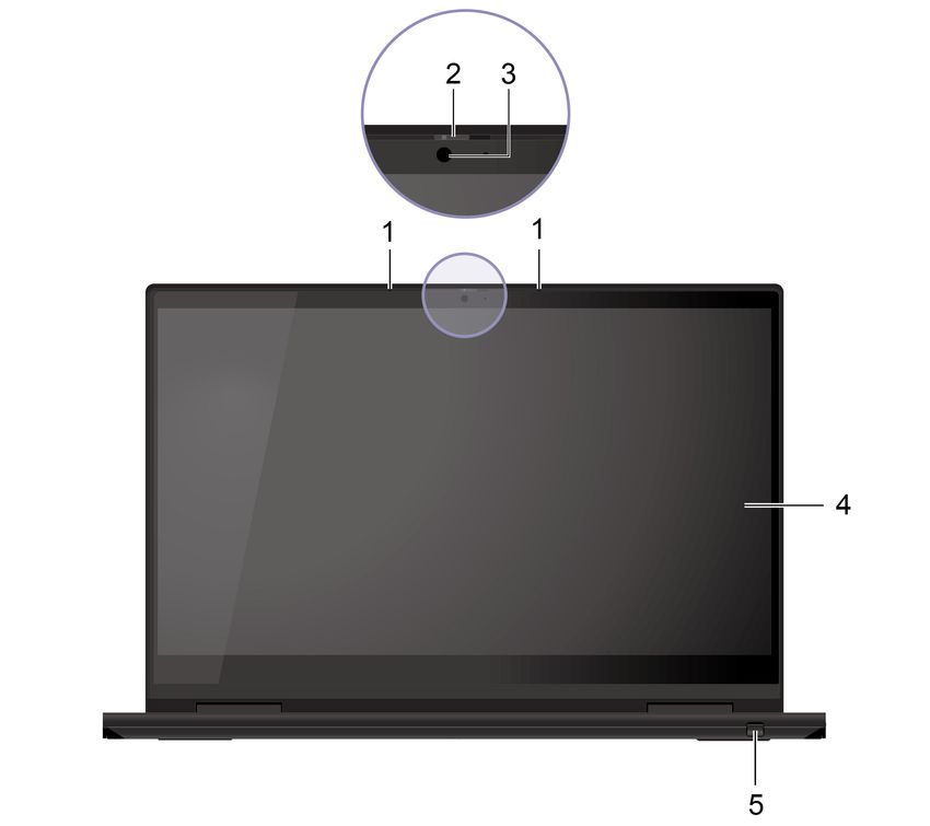
ii Lenovo ThinkPad C13 Yoga Gen 1 Chromebook Hardware Maintenance Manual
About this manual
This manual contains service and reference information for the following Lenovo products:

 Lenovo ThinkPad C13 Yoga Gen 1                   Machine types (MT): 20UX and 20UY
 Chromebook

Use this manual along with the advanced diagnostic tests to troubleshoot problems.

Important:
• This manual is intended only for trained service technicians who are familiar with Lenovo products. Use
  this manual along with the advanced diagnostic tests to troubleshoot problems effectively.
• Depending on the model, some hardware configuration and software programs might not be available on
  the Chromebook™. Some statements in this manual might not be applicable to the Chromebook.
• Before servicing a Lenovo product, be sure to read all the information under Chapter 1 “Safety
  information” on page 1.

© Copyright Lenovo 2020, 2021                                                                               iii
iv Lenovo ThinkPad C13 Yoga Gen 1 Chromebook Hardware Maintenance Manual
Chapter 1. Safety information
This chapter presents the following safety information that you need to be familiar with before you service a
Chromebook.
• “General safety” on page 1
• “Electrical safety” on page 1
• “Safety inspection guide” on page 3
• “Handling devices that are sensitive to electrostatic discharge” on page 3
• “Grounding requirements” on page 4
• “Safety notices (multilingual translations)” on page 4

General safety
Follow these rules to ensure general safety:

• Observe good housekeeping in the area of the machines during and after maintenance.
• When lifting any heavy object:
    1. Ensure that you can stand safely without slipping.
    2. Distribute the weight of the object equally between your feet.
    3. Use a slow lifting force. Never move suddenly or twist when you attempt to lift.
    4. Lift by standing or by pushing up with your leg muscles; this action removes the strain from the
       muscles in your back. Do not attempt to lift any object that weighs more than 16 kg (35 lb) or that you
       think is too heavy for you.
• Do not perform any action that causes hazards to the customer, or that makes the equipment unsafe.
• Before you start the machine, ensure that other service technicians and the customer’s personnel are not
  in a hazardous position.
• Place removed covers and other parts in a safe place, away from all personnel, while you are servicing the
  machine.
• Keep your toolcase away from walk areas so that other people will not trip over it.
• Do not wear loose clothing that can be trapped in the moving parts of a machine. Ensure that your sleeves
  are fastened or rolled up above your elbows. If your hair is long, fasten it.
• Insert the ends of your necktie or scarf inside clothing or fasten it with a nonconductive clip, about 8
  centimeters (3 inches) from the end.
• Do not wear jewelry, chains, metal-frame eyeglasses, or metal fasteners for your clothing, because metal
  objects are good electrical conductors.
• Wear safety glasses when you are hammering, drilling, soldering, cutting wire, attaching springs, using
  solvents, or working in any other conditions that might be hazardous to your eyes.
• After service, reinstall all safety shields, guards, labels, and ground wires. Replace any safety device that
  is worn or defective.
• Reinstall all covers correctly before returning the machine to the customer.
• Fan louvers on the machine help to prevent overheating of internal components. Do not obstruct fan
  louvers or cover them with labels or stickers.

Electrical safety
Observe the following rules when working on electrical equipment.

© Copyright Lenovo 2020, 2021                                                                                     1
Important:
• Use only approved tools and test equipment. Some hand tools have handles covered with a soft material
that does not insulate you when working with live electrical currents.
• Many customers have, near their equipment, rubber floor mats that contain small conductive fibers to
decrease electrostatic discharges (ESD). Do not use this type of mat to protect yourself from electrical
shock.
• Find the room emergency power-off (EPO) switch, disconnecting switch, or electrical outlet. If an electrical
accident occurs, you can then operate the switch or unplug the power cord quickly.
• Do not work alone under hazardous conditions or near equipment that has hazardous voltages.
• Disconnect all power before:
– Performing a mechanical inspection
– Working near power supplies
– Removing or installing main units
• Before you start to work on the machine, unplug the power cord. If you cannot unplug it, ask the customer
to power off the wall box that supplies power to the machine, and to lock the wall box in the off position.
• If you need to work on a machine that has exposed electrical circuits, observe the following precautions:
– Ensure that another person, familiar with the power-off controls, is near you. That person must be there
to switch off the power, if necessary.
– Use only one hand when working with powered-on electrical equipment; keep the other hand in your
pocket or behind your back.
CAUTION:
An electrical shock can occur only when there is a complete circuit. By observing the above rule,
you may prevent a current from passing through your body.
– When using testers, set the controls correctly and use the approved probe leads and accessories for
that tester.
– Stand on suitable rubber mats (obtained locally, if necessary) to insulate you from grounds such as
metal floor strips and machine frames.
Observe the special safety precautions when you work with very high voltages. Instructions for these
precautions are in the safety sections of maintenance information. Use extreme care when measuring high
voltages.
• Regularly inspect and maintain your electrical hand tools for safe operational condition.
• Do not use worn or broken tools and testers.
• Never assume that power has been disconnected from a circuit. First, check that it has been powered off.
• Always look carefully for possible hazards in your work area. Examples of these hazards are moist floors,
nongrounded power extension cables, power surges, and missing safety grounds.
• Do not touch live electrical circuits with the reflective surface of a plastic dental mirror. The surface is
conductive; such touching can cause personal injury and machine damage.
• Do not service the following parts with the power on:
– Power supply units
– Pumps
– Blowers and fans
– Motor generators
– Units similar to those listed above
This practice ensures correct grounding of the units.
• If an electrical accident occurs:
– Use caution; do not become a victim yourself.
– Switch off power.
– Send another person to get medical aid.
2 Lenovo ThinkPad C13 Yoga Gen 1 Chromebook Hardware Maintenance ManualSafety inspection guide
The purpose of this inspection guide is to assist you in identifying potentially unsafe conditions. As each
machine was designed and built, required safety items were installed to protect users and service
technicians from injury. This guide addresses only those items. You should use good judgment to identify
potential safety hazards due to attachment of non-Lenovo features or options not covered by this inspection
guide.
If any unsafe conditions are present, you must determine how serious the apparent hazard could be and
whether you can continue without first correcting the problem.
Consider these conditions and the safety hazards they present:
• Electrical hazards, especially primary power (primary voltage on the frame can cause serious or fatal
electrical shock)
• Explosive hazards, such as a damaged CRT face or a bulging capacitor
• Mechanical hazards, such as loose or missing hardware
To determine whether there are any potentially unsafe conditions, use the following checklist at the
beginning of every service task. Begin the checks with the power off, and the power cord disconnected.
Checklist:
1. Check exterior covers for damage (loose, broken, or sharp edges).
2. Turn off the computer. Disconnect the power cord.
3. Check the power cord for:
a. A third-wire ground connector in good condition. Use a meter to measure third-wire ground
continuity for 0.1 ohm or less between the external ground pin and the frame ground.
b. The power cord should be the authorized type specified for your computer. Go to: https://
support.lenovo.com/partslookup.
c. Insulation must not be frayed or worn.
4. Check for cracked or bulging batteries.
5. Remove the cover.
6. Check for any obvious non-Lenovo alterations. Use good judgment as to the safety of any non-Lenovo
alterations.
7. Check inside the unit for any obvious unsafe conditions, such as metal filings, contamination, water or
other liquids, or signs of fire or smoke damage.
8. Check for worn, frayed, or pinched cables.
9. Check that the power-supply cover fasteners (screws or rivets) have not been removed or tampered
with.
Handling devices that are sensitive to electrostatic discharge
Any computer part containing transistors or integrated circuits (ICs) should be considered sensitive to
electrostatic discharge (ESD). ESD damage can occur when there is a difference in charge between objects.
Protect against ESD damage by equalizing the charge so that the machine, the part, the work mat, and the
person handling the part are all at the same charge.
Notes:
1. Use product-specific ESD procedures when they exceed the requirements noted here.
Chapter 1. Safety information 32. Ensure that the ESD protective devices you use have been certified (ISO 9000) as fully effective.
When handling ESD-sensitive parts:
• Keep the parts in protective packages until they are inserted into the product.
• Avoid contact with other people.
• Wear a grounded wrist strap against your skin to eliminate static on your body.
• Prevent the part from touching your clothing. Most clothing is insulative and retains a charge even when
you are wearing a wrist strap.
• Use a grounded work mat to provide a static-free work surface. The mat is especially useful when
handling ESD-sensitive devices.
• Select a grounding system, such as those listed below, to provide protection that meets the specific
service requirement.
Note: The use of a grounding system to guard against ESD damage is desirable but not necessary.
– Attach the ESD ground clip to any frame ground, ground braid, or green-wire ground.
– When working on a double-insulated or battery-operated system, use an ESD common ground or
reference point. You can use coax or connector-outside shells on these systems.
– Use the round ground prong of the ac plug on ac-operated computers.
Grounding requirements
Electrical grounding of the computer is required for operator safety and correct system function. Proper
grounding of the electrical outlet can be verified by a certified electrician.
Safety notices (multilingual translations)
The safety notices in this section are provided in the following languages:
• English
• Arabic
• Brazilian Portuguese
• French
• German
• Hebrew
• Japanese
• Korean
• Spanish
• Traditional Chinese
DANGER
4 Lenovo ThinkPad C13 Yoga Gen 1 Chromebook Hardware Maintenance ManualDANGER
DANGER
DANGER
DANGER
DANGER
DANGER
Chapter 1. Safety information 5DANGER 6 Lenovo ThinkPad C13 Yoga Gen 1 Chromebook Hardware Maintenance Manual
PERIGO

         Chapter 1. Safety information   7
PERIGO PERIGO PERIGO PERIGO 8 Lenovo ThinkPad C13 Yoga Gen 1 Chromebook Hardware Maintenance Manual
PERIGO

PERIGO

PERIGO

DANGER

DANGER

         Chapter 1. Safety information   9
DANGER DANGER DANGER DANGER DANGER 10 Lenovo ThinkPad C13 Yoga Gen 1 Chromebook Hardware Maintenance Manual
DANGER

VORSICHT

VORSICHT

VORSICHT

VORSICHT

           Chapter 1. Safety information   11
VORSICHT VORSICHT VORSICHT VORSICHT 12 Lenovo ThinkPad C13 Yoga Gen 1 Chromebook Hardware Maintenance Manual
Chapter 1. Safety information 13
14 Lenovo ThinkPad C13 Yoga Gen 1 Chromebook Hardware Maintenance Manual
Chapter 1. Safety information 15
16 Lenovo ThinkPad C13 Yoga Gen 1 Chromebook Hardware Maintenance Manual
Chapter 1. Safety information 17
18 Lenovo ThinkPad C13 Yoga Gen 1 Chromebook Hardware Maintenance Manual
Chapter 1. Safety information 19
20 Lenovo ThinkPad C13 Yoga Gen 1 Chromebook Hardware Maintenance Manual
Chapter 2. General checkout
This chapter presents the following information:
• “What to do first” on page 21
• “Power system checkout” on page 22

Some descriptions in this chapter might not apply to your particular computer.

Before you go to the checkout guide, be sure to read the following important notes.

 Important notes:
 • Only certified trained personnel should service the computer.
 • Before replacing any FRU, read the entire page on removing and replacing FRUs.
 • When you replace FRUs, it is recommended to use new nylon-coated screws.
 • Be extremely careful during such write operations as copying, saving, or formatting. Drives in the computer
   that you are servicing sequence might have been altered. If you select an incorrect drive, data or programs might be
   overwritten.
 • Replace a FRU only with another FRU of the correct model. When you replace a FRU, ensure that the model of
   the machine and the FRU part number are correct.
 • A FRU should not be replaced because of a single, unreproducible failure. Single failures can occur for a variety
   of reasons that have nothing to do with a hardware defect, such as cosmic radiation, ESD, or software errors.
   Consider replacing a FRU only when a problem recurs. If you suspect that a FRU is defective, clear the error log and
   run the test again. If the error does not recur, do not replace the FRU.
 • Be careful not to replace a nondefective FRU.

What to do first
When you return a FRU, you must include the following information in the parts exchange form or parts return
form that you attach to it:
  1. Name and phone number of service technician
  2. Date of service
  3. Date on which the machine failed
  4. Date of purchase
  5. Failure symptoms, error codes appearing on the display, and beep symptoms
  6. Procedure index and page number in which the failing FRU was detected
  7. Failing FRU name and part number
  8. Machine type, model number, and serial number
  9. Customer’s name and address

Note: During the warranty period, the customer may be responsible for repair costs if the computer damage
was caused by misuse, accident, modification, unsuitable physical or operating environment, or improper
maintenance by the customer. Following is a list of some common items that are not covered under warranty
and some symptoms that might indicate that the system was subject to stress beyond normal use.

Before checking problems with the computer, determine whether the damage is covered under the warranty
by referring to the following list:

The following are not covered under warranty:
• LCD panel cracked from the application of excessive force or from being dropped
• Scratched (cosmetic) parts
• Distortion, deformation, or discoloration of the cosmetic parts

© Copyright Lenovo 2020, 2021                                                                                        21
•    Plastic parts, latches, pins, or connectors that have been cracked or broken by excessive force
•    Damage caused by liquid spilled into the system
•    Damage caused by the improper insertion of a PC Card or the installation of an incompatible card
•    Diskette drive damage caused by pressure on the diskette drive cover, foreign material in the drive, or the
     insertion of a diskette with multiple labels
•    Damaged or bent diskette eject button
•    Fuses blown by attachment of a nonsupported device
•    Forgotten computer password (making the computer unusable)
•    Sticky keys caused by spilling a liquid onto the keyboard
•    Use of an incorrect ac power adapter on laptop products

The following symptoms might indicate damage caused by nonwarranted activities:
• Missing parts might be a symptom of unauthorized service or modification.
• Check for obvious damage to a hard disk drive. If the spindle of a hard disk drive becomes noisy, the hard
  disk drive might have been dropped or subject to excessive force.

Power system checkout
If you suspect a power problem, see the appropriate one of the following power supply checkouts:
• “Checking the ac power adapter” on page 22
• “Checking the built-in battery and operational charging” on page 22

Checking the ac power adapter
You are here because the computer fails only when the ac power adapter is used.
• If the system status indicator is not on when an ac power source is connected, check the power cord of
  the ac power adapter for correct continuity and installation.
• If the computer does not charge during operation, go to “Checking the built-in battery and operational
  charging” on page 22.

To check the ac power adapter, measure the output voltage across the plug of the ac power adapter cable to
see if the voltage is correct.

Notes:
• Noise from the ac power adapter does not always indicate a defect.
• Ensure that you use the ac power adapter that is shipped with the computer to provide enough power to
  the computer. Otherwise, a message might be displayed, prompting you that the computer will not be
  charged or will be charged slowly.

Checking the built-in battery and operational charging
This computer supports only batteries specially designed for this specific system and manufactured by
Lenovo or an authorized builder. The system does not support unauthorized batteries or batteries designed
for other systems. If an unauthorized battery or a battery designed for another systems is installed, the
system will not charge.

Attention: Lenovo has no responsibility for the performance or safety of unauthorized batteries, and
provides no warranties for failures or damage arising out of their use.

To check whether the battery charges properly during operation, do the following:
    1. Discharge the battery until the remained battery power is less than 50%.
    2. Connect the computer to ac power to charge the battery. If the battery status icon indicates that the
       battery is not charging, remove the battery and let it return to room temperature.
    3. Reinstall the battery. If the battery is still not charging, replace the battery.

22      Lenovo ThinkPad C13 Yoga Gen 1 Chromebook Hardware Maintenance Manual
4. Check the battery status icon again. If the same error still exists, replace the system board.
Chapter 2. General checkout 2324 Lenovo ThinkPad C13 Yoga Gen 1 Chromebook Hardware Maintenance Manual
Chapter 3. Create and use a USB repair shim
This chapter contains the following topics:
   “What is a USB repair shim?” on page 25
   “Create a USB repair shim” on page 25
   “Use the USB repair shim” on page 26

What is a USB repair shim?
You can create a USB repair shim by writing a repair shim image to a USB storage drive. With the USB repair
shim, you can:
• Refresh the Chromebook system with the latest firmware.
• Diagnose problems and restore the system to factory settings.

Note: Before replacing any FRUs, use the USB repair shim to diagnose and identify problems.

When you use the USB repair shim to diagnose problems, the Chromebook enters the factory-test-image
environment and runs through the following factory test items.

Table 1. Factory test items

 Test item                      Description

                                Required Test is designed to test items such as VPD data writing and HWID.
 Required Test                  Note: Please ensure that all required test items haven been passed. Otherwise, the
                                overall test is marked as failed.
                                The optional test include two parts that are Function test and RunIn Test.
                                • The Function Test includes items such as HDMI test or USB-C/USB-A test.
 Optional Test
                                • The Run In Test is designed to test how the system functions under stress by
                                  running the maximum workload has been already combined here. It will take about 15
                                  minutes to finish.
 Google Required Tests          The GRT is designed to check the system status and help reset the system back to
 (GRT)                          factory settings. If any test fails, the GRT has to be forced to end.

Create a USB repair shim
Step 1.   Prepare a USB storage drive with at least 8 GB of storage capacity.

          Attention: The creation process deletes anything stored on the USB storage drive. To avoid data
          loss, backup all the data that you want to keep.
Step 2.   Download the image file of the repair shim from https://support.lenovo.com. A Lenovo service
          credential is required to download the image file.

          Note: Make sure to download the latest version of the image file. A shim created with an earlier
          version of the image file might cause the repair process to fail.
Step 3.   Use a disk imaging tool to write the downloaded image to the USB storage drive. An open-source
          tool Win32 Disk Imager is available at http://sourceforge.net/projects/win32diskimager.

© Copyright Lenovo 2020, 2021                                                                                        25
Use the USB repair shim
Step 1. Press Esc and . Then, press the power button to enter the recovery mode.
Step 2. Press Crtl+D and then press Enter in recovery mode. Then, the Chromebook will restart
automatically.
Step 3. Enable the developer mode on the Chromebook . The Chromebook will restart and enter the
operating system automatically when the process is completed.
Note: It might take several minutes to enter the developer mode.
Step 4. Press Crtl + Alt + F2 to enter the Text mode (VT2 mode).
Step 5. Log in with root and type enable_dev_usb_boot in the command line to start the Chromebook
from USB key function.
Step 6. Press Ctrl + Alt +F1 to enter the normal mode. Then, turn off the Chromebook and then disconnect
the built-in battery.
Step 7. Insert the USB repair shim key and attach the ac power adapter to the Chromebook. A prompt
will be displayed on the BIOS screen to inform that you are in developer mode. Then, press Ctrl
+U to let the Chromebook start from the USB key.
Step 8. The USB repair shim image will be automatically installed. When this process is finished, a prompt
will be displayed on the screen.
Step 9. Detach the ac power adapter and reconnect the built-in battery to the system board.
Step 10. Reattach the ac power adapter to the Chromebook. Then, the Chromebook will enter the factory-
test image environment.
Step 11. Remove the USB repair shim from the Chromebook and store it in a safe place.
Step 12. Follow the on-screen instructions to start the Required test.
Note: If the system board is replaced, you are required to enter the Vital Product Data (VPD). The
VPD is a 20 — character string.
Table 2. Combination of the 20 – character VPD
Preceding characters Machine type Model number Serial number
“1s”, 2 digits 7 digits 3 digits 8 digits
Step 13. Start the Optional test (Optional test includes the Functional Test and RunIn test).
Step 14. Follow the on-screen instructions to start the GRT. If the tests finish successfully, all data stored on
the Chromebook is deleted and the Chromebook is turned off. If the GRT fails, it might result from
hardware identity (HWID) mismatch and write-protect malfunction. Use the following information to
identify problems.
26 Lenovo ThinkPad C13 Yoga Gen 1 Chromebook Hardware Maintenance ManualProblem Description
HWID mismatch A set of valid hardware identities (HWIDs) is provided by Google. Google logs the
exact hardware combination into a Chromebook and creates an HWID. The HWID
is used for the following purposes:
• Auto-update new patches and software for the lifetime of the Chromebook
• Reset the Chromebook to factory settings
HWID mismatch can be caused by using unauthorized or missing parts. If the
write-protect function is not turned off before recovering the Chromebook with
the USB repair shim, it can also cause HWID mismatch.
Write-protect The Chromebook system cannot be finalized until the write-protect function is
malfunction turned on.
Note: You can terminate the GRT when the tests have to be bypassed because they cannot be
performed. To end the process, press f.
Chapter 3. Create and use a USB repair shim 2728 Lenovo ThinkPad C13 Yoga Gen 1 Chromebook Hardware Maintenance Manual
© Copyright Lenovo 2020, 2021 29
Chapter 4. Use the keyboard shortcuts
The function keys on the keyboard help you work more easily and effectively.

                         Go to the previous page.

                         Go to the next page.

                         Refresh your current page.

                         Make the current window full screen.

                         Open the task view to see all your open windows.

                         Darken the display.

                         Brighten the display.

                         Mute the speakers.

                         Decrease the speaker volume.

                         Increase the speaker volume.

                         Lock the screen.

Your Chromebook also supports some key combinations.

 Ctrl +                  Take a screenshot.

                         Switch the letter case between the upper case and lower case.
 Alt +
                         Lock the screen.
 L+
 Ctrl + Alt + ?          View all keyboard shortcuts.

To change the keyboard settings:
 1. Click the setting icon in the system tray, and then click Device ➙ Keyboard.
 2. Follow the on-screen instructions to change the settings as you prefer.

30    Lenovo ThinkPad C13 Yoga Gen 1 Chromebook Hardware Maintenance Manual
Chapter 5. Locations This chapter introduces the locations of the hardware components on your computer. Locating controls and connectors This topic introduces the locations of the controls and connectors. Front 1. Microphones 4. Multi-touch screen 2. ThinkShutter 5. Lenovo Garaged USI pen* 3. Camera * for selected models © Copyright Lenovo 2020, 2021 31
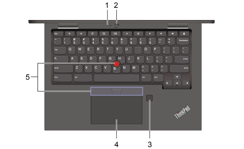
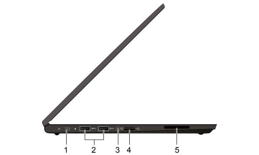
Base

 1. Microphone*                                              4. Touchpad

 2. World-Facing camera*                                     5. TrackPoint® pointing device

 3. Fingerprint reader*

* for selected models

Left

 1. Power connector (USB-C®)                                 4. microSD card slot

 2. USB 3.2 Gen 1 connectors                                 5. Speaker

 3. Audio connector

32     Lenovo ThinkPad C13 Yoga Gen 1 Chromebook Hardware Maintenance Manual
Right

 1. Speaker                                            4. HDMI™ connector

 2. Power button                                       5. USB-C (3.2 Gen 2) connector

 3. Volume button                                      7. Security-lock slot

Locating FRUs and CRUs
This topic introduces the following service parts:
   “Major FRUs and CRUs” on page 34
   “LCD FRUs” on page 36
   “Miscellaneous parts” on page 37

Notes:
• Each FRU is available for all types or models, unless otherwise specified.
• CRU statement for customers:
  You can resolve some problems with your product with a replacement part you can install yourself, called
  a “Customer Replaceable Unit” or “CRU.” Some CRUs are designated as self-service CRUs and others
  are designated as optional-service CRUs. Installation of self-service CRUs is your responsibility. For
  optional-service CRUs, you can either install the CRU yourself or you can request that a Service Provider
  install the CRU according to the warranty service for your product. If you intend on installing the CRU,
  Lenovo will ship the CRU to you. CRU information and replacement instructions are shipped with your
  product and are available from Lenovo at any time upon request. You can find a list of CRUs for your
  product in this Hardware Maintenance Manual. An electronic version of this manual can be found at
  https://support.lenovo.com. Click Documentation and then follow the on-screen instructions to find the
  manual for your product. You might be required to return the defective CRU. When return is required: (1)
  return instructions, a prepaid shipping label, and a container will be included with the replacement CRU;
  and (2) you might be charged for the replacement CRU if Lenovo does not receive the defective CRU
  within thirty (30) days of your receipt of the replacement CRU. See your Lenovo Limited Warranty
  documentation for full details.
  Chromebook contains the following types of CRUs and FRUs:
  – Self-service CRUs: Refer to parts that can be installed or replaced easily by customer themselves or
    by trained service technicians at an additional cost.

                                                                                        Chapter 5. Locations   33
– Optional-service CRUs: Refer to parts that can be installed or replaced by customers with a greater
skill level. Trained service technicians can also provide service to install or replace the parts under the
type of warranty designated for the customer’s machine.
– FRUs: Refer to parts that must be installed or replaced only by trained service technicians. If customers
choose to replace the FRUs by themselves, the product warranty might be affected.
Major FRUs and CRUs
Note: Depending on the Chromebook model, your Chromebook might look different from the illustration
above.
Table 3. Major FRUs and CRUs
No. FRU description Self-service CRU Optional-service CRU
1 LCD unit No No
34 Lenovo ThinkPad C13 Yoga Gen 1 Chromebook Hardware Maintenance ManualTable 3. Major FRUs and CRUs (continued)
2 World-Facing camera board* No No
3 World-Facing camera cable* No No
4 Keyboard assembly No No
5 Thermal fan assembly No No
6 USB board cable No No
7
8 USB board No No
9 Short USB board bracket No No
10 M.2 solid-state drive cover* No No
11 M.2 2242 solid-state drive* No No
12 M.2 2280 solid-state drive* No No
13 Wireless LAN card No No
14 Pen charger with cable No No
15 Base cover assembly Yes No
16 Built-in battery No No
17 Fingerprint reader cable* No No
18 Fingerprint reader* No No
19 Fingerprint reader bracket* No No
20 Speaker assembly No No
21 System board No No
22 Long USB board bracket No No
23 Touchpad cable No No
24 Touchpad No No
25 Dummy pen cap* No No
26 Lenovo Garaged USI pen* Yes No
a Power cord Yes No
b ac power adapter Yes No
c Miscellaneous parts kits (See No No
“Miscellaneous parts” on page
37)
* for selected models
Chapter 5. Locations 35LCD FRUs Note: Depending on the Chromebook model, your Chromebook might look different from the illustration above. Table 4. LCD FRUs and CRUs No. FRU description Self-service CRU Optional-service CRU 1 LCD panel No No 2 Microphone rubber No No 3 Microphone board No No 4 Microphone with sensor board* No No 5 Camera board No No 6 Camera cable No No 7 Camera with microphone cable No No 8 LED cable No No 9 LCD cover assembly No No 36 Lenovo ThinkPad C13 Yoga Gen 1 Chromebook Hardware Maintenance Manual
Table 4. LCD FRUs and CRUs (continued)

 10    LCD elastic tapes*                No                                No

 11    LCD hinge assembly                No                                No

 12    LCD hinge rubber                  No                                No

 13    LCD cable                         No                                No
 14    Strip cover                       No                                No

* for selected models

Miscellaneous parts
Table 5. Miscellaneous parts

 FRU descriptions                             Self-service CRU               Optional-service CRU

 Screw pack:                                  No                             No
 • Screw M2.5 x L2.3, black (6)
 • Screw M2 x L2, silver (1)
 • Screw M2 x L2.5, silver (3)
 • Screw M2 x L4.5, silver (9)
 • Screw M2.5 x L5, black (4)
 • Screw M2 x L3.5, black (9)
 • Screw M2 x L2, black (4)
 • Screw M2.5 x L7.5 , black (2)
 • Screw M2 x L7.5 , black (4)
 • Screw M2 x L5.5 , black (2)
 • Spec

Connector and cable guide
This section provides information for Lenovo authorized service technicians to help identify connectors and
cables for replacement purpose. To view each FRU and the exploded illustration of the Chromebook, see
Major FRUs and CRUs and LCD FRUs.

Note: Depending on your model, some connectors or cables might not be available.

                                                                                      Chapter 5. Locations   37
System board
Item Connector (location) Internal cable required Cable connection
1 Camera with microphone and No Connect one end of the cable to the camera
LED connector (internal) with microphone and LED board and the
other end to this connector.
2 Wireless-LAN card slot No Insert the wireless-LAN card into this slot.
(internal)
3 World-Facing camera board World-Facing camera Connect one end of the World-Facing
connector (internal) cable camera cable to the World-Facing camera
board and the other end to this connector.
4 LCD connector (internal) LCD cable Connect one end of the LCD cable to the
LCD panel and the other end to this
connector.
5 USB-C connector (external) No Connect USB-C compatible devices or a
USB-C power adapter to this connector.
6 USB 3.2 connectors Gen 1 No Connect USB-compatible devices to this
(external) connector.
7 Audio connector (external) No Connect headphones or a headset with 3.5-
mm (0.14-inch) 4-pole plug to this connector.
8 microSD card slot (external) No Insert a microSD card into this slot
9 Speaker assembly connector Speaker assembly cable The speaker assembly comes with cable.
(internal) Connect the cable to this connector.
10 Keyboard connectors Keyboard assembly The keyboard assembly comes with the
11 (internal) cables cables. Connect the cables to these
connectors.
12 Touchpad connector (internal) Touchpad cable Connect one end to the touchpad and the
other end to this connector.
13 Fingerprint reader connector Fingerprint-reader cable Connect one end to the fingerprint reader
(internal) card and the other end to this connector.
14 Battery connector (internal) Battery with cable The built-in battery comes with a cable.
Connect the cable to this connector.
15 M.2 solid-state drive No Insert the M.2 solid-state drive into this slot.
connector (internal)
38 Lenovo ThinkPad C13 Yoga Gen 1 Chromebook Hardware Maintenance ManualItem Connector (location) Internal cable required Cable connection
16 Thermal fan connector Thermal fan assembly The thermal fan assembly comes with cable.
(internal) cable Connect the cable to this connector.
17 I/O board connector (internal) I/O board cable Connect one end of the cable to the USB
board and the other end to this connector.
Looking up FRU information
For detailed FRU information, including part numbers, descriptions, and substitution part numbers, go to:
https://support.lenovo.com/partslookup
Chapter 5. Locations 3940 Lenovo ThinkPad C13 Yoga Gen 1 Chromebook Hardware Maintenance Manual
Chapter 6. FRU replacement notices
This chapter presents notices related to removing and replacing parts. Read this chapter carefully before
replacing any FRU.

CRU statement for customers:
You can resolve some problems with your product with a replacement part you can install yourself, called a
“Customer Replaceable Unit” or “CRU.” Some CRUs are designated as self-service CRUs and others are
designated as optional-service CRUs. Installation of self-service CRUs is your responsibility. For optional-
service CRUs, you can either install the CRU yourself or you can request that a Service Provider install the
CRU according to the warranty service for your product. If you intend on installing the CRU, Lenovo will ship
the CRU to you. CRU information and replacement instructions are shipped with your product and are
available from Lenovo at any time upon request. You can find a list of CRUs for your product in this Hardware
Maintenance Manual. An electronic version of this manual can be found at https://support.lenovo.com. Click
Documentation and then follow the on-screen instructions to find the manual for your product. You might be
required to return the defective part that is replaced by the CRU. When return is required: (1) return
instructions, a prepaid shipping label, and a container will be included with the replacement CRU; and (2) you
might be charged for the replacement CRU if Lenovo does not receive the defective CRU within thirty (30)
days of your receipt of the replacement CRU. See your Lenovo Limited Warranty documentation for full
details.

Service tool kit
Ensure that the following service tool kit is prepared before you service a ThinkPad Chromebook computer.

 No.      Tool name                                         Tool type

 1        Phillips-head screwdriver                         Common tool

 2        Torx-head screwdriver                             Common tool
 3        Conductive tweezers                               Common tool
 4        Hexagonal socket                                  Common tool

 5        Silicone grease                                   Consumable tool

 6        Polyamide tape                                    Consumable tool
 7        Mylar tape                                        Consumable tool

 8        Eraser                                            Consumable tool
 9        Electrical tape                                   Consumable tool

 10       Double-sided tape                                 Consumable tool

 11       Conductive tape                                   Consumable tool

Note: The silicone grease can be applied to the surfaces of the microprocessor and heatsink to eliminate air
gaps. The hexagonal socket is used to pick up the antenna connectors.

Screw notices
Loose screws can cause a reliability problem. In the ThinkPad notebook Chromebook, this problem is
addressed with special nylon-coated screws that have the following characteristics:

© Copyright Lenovo 2020, 2021                                                                               41
• They maintain tight connections.
• They do not easily come loose, even with shock or vibration.
• They are harder to tighten.

Do the following when you service this machine:
• Keep the screw kit in your tool bag. For the part number of the screw kit, go to https://support.lenovo.com/
  partslookup.
• It is recommended to use new screws.
• It is recommended to use each screw only once.

Tighten screws as follows:
• Plastic to plastic
  Turn an additional 90 degrees after the screw head touches the surface of the plastic part.

• Logic card to plastic
  Turn an additional 180 degrees after the screw head touches the surface of the logic card.

Notes:
• Ensure that you use the correct screw. It is recommended to use new screws for replacements. If you
  have a torque screwdriver, tighten all screws firmly to the torque specified in the screw information table
  for each step.
• Ensure that torque screwdrivers are calibrated correctly following country specifications.

42   Lenovo ThinkPad C13 Yoga Gen 1 Chromebook Hardware Maintenance Manual
Chapter 7. FRU replacement notices
This chapter presents notices related to removing and replacing parts. Read this chapter carefully before
replacing any FRU.

CRU statement for customers:
You can resolve some problems with your product with a replacement part you can install yourself, called a
“Customer Replaceable Unit” or “CRU.” Some CRUs are designated as self-service CRUs and others are
designated as optional-service CRUs. Installation of self-service CRUs is your responsibility. For optional-
service CRUs, you can either install the CRU yourself or you can request that a Service Provider install the
CRU according to the warranty service for your product. If you intend on installing the CRU, Lenovo will ship
the CRU to you. CRU information and replacement instructions are shipped with your product and are
available from Lenovo at any time upon request. You can find a list of CRUs for your product in this Hardware
Maintenance Manual. An electronic version of this manual can be found at https://support.lenovo.com. Click
Documentation and then follow the on-screen instructions to find the manual for your product. You might be
required to return the defective part that is replaced by the CRU. When return is required: (1) return
instructions, a prepaid shipping label, and a container will be included with the replacement CRU; and (2) you
might be charged for the replacement CRU if Lenovo does not receive the defective CRU within thirty (30)
days of your receipt of the replacement CRU. See your Lenovo Limited Warranty documentation for full
details.

General guidelines
When removing or replacing a FRU, ensure that you observe the following general guidelines:
 1. Do not try to service any computer unless you have been trained and certified. An untrained person runs
    the risk of damaging parts.
 2. Begin by removing any FRUs that have to be removed before replacing the failing FRU. Any such FRUs
    are listed at the beginning of each FRU replacement procedure. Remove them in the order in which they
    are listed.
 3. Follow the correct sequence in the steps for removing a FRU, as shown in the illustrations by the
    numbers in square callouts.
 4. When removing a FRU, move it in the direction as shown by the arrow in the illustration.
 5. To install a new FRU in place, perform the removal procedure in reverse and follow any notes that
    pertain to replacement.
 6. If screws are missing, look up details in “Miscellaneous parts” on page 37 for replacement screws and
    order them through the Lenovo CRM system.
 7. When replacing the base cover, reapply all labels that come with the replacement base cover. If some
    original labels are not included with the replacement base cover, peal them off from the original base
    cover and paste them on the replacement base cover.

     DANGER

 Before removing any FRU or CRU, shut down the computer and unplug all power cords from
 electrical outlets.

Attention:
• After replacing a FRU, do not turn on the computer until you have ensured that all screws, springs, and
  other small parts are in place and none are loose inside the computer. Verify this by shaking the computer
  gently and listening for rattling sounds. Metallic parts or metal flakes can cause electrical short circuits.

© Copyright Lenovo 2020, 2021                                                                                43
• The system board is sensitive to and can be damaged by ESD. Before touching it, establish personal grounding by touching a ground point with one hand or by using an ESD strap (P/N 6405959). Before servicing the Chromebook Carefully read this topic before servicing the Chromebook. Disabling the built-in battery Before replacing any FRU, ensure that you disable the built-in battery. To disable the built-in battery, press together with the power button for about five seconds, and at the same time detach the ac power adapter from the Chromebook. Note: Power supply from the built-in battery will resume after you reconnect the Chromebook to the ac power adapter. 1010 Lenovo Garaged USI pen (for selected models) Removal step of the Lenovo Garaged USI pen Note: Ensure that you reinstall the Lenovo Garaged USI pen after finishing the servicing. 1020 Base cover assembly For access, remove these FRUs in order: • “1010 Lenovo Garaged USI pen (for selected models)” on page 44 44 Lenovo ThinkPad C13 Yoga Gen 1 Chromebook Hardware Maintenance Manual
Removal steps of the base cover assembly

Applying labels to the base cover assembly

The following illustration and table show the label areas and what labels are applied in each area.

 1 GEO label                                             2 Asset tag label

 3 Country label                                         4 Serial number label

1030 Built-in battery
For access, remove these FRUs in order:
• “1010 Lenovo Garaged USI pen (for selected models)” on page 44
• “1020 Base cover assembly” on page 44

Important notices for replacing a built-in battery

Attention: Lenovo has no responsibility for the performance or safety of unauthorized batteries, and
provides no warranties for failures or damage arising out of their use.

A battery FRU should not be replaced unless this diagnostic test shows that the battery is defective. The only
exception to this is if the battery is physically damaged or a customer is reporting a possible safety issue.

                                                                             Chapter 7. FRU replacement notices   45
If the diagnostic program is not installed on the Chromebook, the customer should download and install the
program to diagnose the battery, before getting a non-physically damaged battery replaced. Note that the
replacement of a physically damaged battery is not covered by the warranty.
Removal steps of the built-in battery
DANGER
Use only the authorized battery specified for your Chromebook. Any other battery could ignite or
explode.
Step Screw (quantity) Color Torque
2 M2 × L3.5 mm, black nickel (5) Black 0.18 Nm
(1.85 kgf-cm)
1040 Wireless LAN card
For access, remove these FRUs in order:
• “1010 Lenovo Garaged USI pen (for selected models)” on page 44
• “1020 Base cover assembly” on page 44
Removal steps of the wireless LAN card
Unplug the connectors by using the antenna RF connector removal tool or pick the connectors with your
fingers and gently unplug them as shown.
46 Lenovo ThinkPad C13 Yoga Gen 1 Chromebook Hardware Maintenance ManualStep Screw (quantity) Color Torque
2 M2 × 2.5 mm, flat-head, nylon-coated (1) Black 0.18 Nm
(1.85 kgf-cm)
1050 M.2 solid-state drive and M.2 solid-state drive cover
For access, remove these FRUs in order:
• “1010 Lenovo Garaged USI pen (for selected models)” on page 44
• “1020 Base cover assembly” on page 44
Attention: The M.2 solid-state drive is sensitive. Inappropriate handling might cause damage and
permanent loss of data.
When handling the M.2 solid-state drive, observe the following guidelines:
• Replace the M.2 solid-state drive only for upgrade or repair. The M.2 solid-state drive is not designed for
frequent changes or replacement.
• Before replacing the M.2 solid-state drive, make a backup copy of all the data that you want to keep.
• Do not apply pressure to the M.2 solid-state drive.
• Do not touch the contact edge of the M.2 solid-state drive. Otherwise the M.2 solid-state drive might get
damaged.
• Do not make the M.2 solid-state drive subject to physical shocks or vibration. Put the M.2 solid-state drive
on a soft material, such as cloth, to absorb physical shocks.
If your Chromebook is installed with a hybrid solid-state drive (with Intel Optane memory), go to https://
support.lenovo.com/docs/tg_ssd to know the details on how to replace it.
Chapter 7. FRU replacement notices 47Removal steps of the M.2 solid-state drive and M.2 solid-state drive cover
Note: Depending on the model, your M.2 solid-state drive might look different from the illustration above.
Step Screw (quantity) Color Torque
2 M2 × L2.5 mm, large flat (1) Black 0.18 Nm
(1.85 kgf-cm)
When installing: Remember to install a mylar before you upgrade your 2242 solid-state drive to 2280 solid-
state drive or you install a new M.2 2280 solid-state drive on the empty SSD slot.
1060 I/O board brackets
For access, remove these FRUs in order:
• “1010 Lenovo Garaged USI pen (for selected models)” on page 44
• “1020 Base cover assembly” on page 44
Removal steps of long I/O board bracket
Note: A Mylar film might cover the screw. To access it, peel off the film first.
48 Lenovo ThinkPad C13 Yoga Gen 1 Chromebook Hardware Maintenance ManualStep Screw (quantity) Color Torque
1 M2 × 4.5 mm, flat-head, nylon-coated (3) Silver 0.18 Nm
(1.85 kgf-cm)
Removal steps of short I/O board bracket
Step Screw (quantity) Color Torque
1 M2 × 4.5 mm, flat-head, nylon-coated (3) Silver 0.18 Nm
(1.85 kgf-cm)
1070 I/O board cable and I/O board
For access, remove these FRUs in order:
• “1010 Lenovo Garaged USI pen (for selected models)” on page 44
• “1020 Base cover assembly” on page 44
• “1060 I/O board brackets” on page 48
Chapter 7. FRU replacement notices 49Removal steps of the I/O board cable and I/O board Lift the speaker before you remove the I/O board. 1080 Thermal fan assembly For access, remove these FRUs in order: • “1010 Lenovo Garaged USI pen (for selected models)” on page 44 • “1020 Base cover assembly” on page 44 50 Lenovo ThinkPad C13 Yoga Gen 1 Chromebook Hardware Maintenance Manual
Removal steps of the thermal fan assembly

                                                      2e

                                                                     2a

                                               2e
                                                           2e
                                                                               2c
                                                                2d
                                                                          2b

When installing:
• Always wear fingerstalls when handling the thermal fan assembly. Do not touch or hold any part of the
  thermal fan assembly with bare fingers.
• Before you attach the thermal fan assembly to the Chromebook, apply thermal grease, at an amount of
  0.2 grams, on the part marked a as shown in the following illustrations. Either too much or too less
  application of grease can cause a thermal problem due to imperfect contact with a component.

• Do not touch the thermal grease.
• Do not press, touch, or rotate the fan impeller.
• Do not touch the fan inlet hole.
• Do not twist or pull the cable of the thermal fan assembly.
• Do not apply pressure on the top and base covers of the thermal fan assembly.
• Do not press the heat pipe. Hold both sides of the heat pipe when you take the thermal fan assembly.
• Do not shake or drop the thermal fan assembly.
• Ensure that the fan connector is attached firmly.
• Replace the thermal fan assembly if you observe the following:
  – The cover of the thermal fan assembly is deformed or damaged.
  – There is abnormal noise during rotation.

1090 LCD unit
For access, remove these FRUs in order:
• “1010 Lenovo Garaged USI pen (for selected models)” on page 44

                                                                                Chapter 7. FRU replacement notices   51
• “1020 Base cover assembly” on page 44
Removal steps of the LCD unit
Step Screw (quantity) Color Torque
6 M2.5 × L5 mm, flat-head (4) Black 0.29 Nm
(3.0 kgf-cm)
52 Lenovo ThinkPad C13 Yoga Gen 1 Chromebook Hardware Maintenance ManualWhen installing: Ensure that you attach the connectors firmly.
Attention: When you route the cables, ensure that they are not subject to any tension. Tension could cause
the cables to be damaged by the cable guides, or a wire to be broken.
1110 Pen charger cable
For access, remove these FRUs in order:
• “1010 Lenovo Garaged USI pen (for selected models)” on page 44
• “1020 Base cover assembly” on page 44
Removal steps of the pen charger cable
Step Screw (quantity) Color Torque
3 M2 × L4.5 mm, large flat (1) Silver 0.18 Nm
(1.85 kgf-cm)
Chapter 7. FRU replacement notices 531120 Speaker assembly For access, remove these FRUs in order: • “1010 Lenovo Garaged USI pen (for selected models)” on page 44 • “1020 Base cover assembly” on page 44 • “1030 Built-in battery” on page 45 • “1110 Pen charger cable” on page 53 Removal steps of the speaker assembly When installing: Ensure that the connector is attached firmly. 1130 Touchpad and touchpad cable For access, remove these FRUs in order: • “1010 Lenovo Garaged USI pen (for selected models)” on page 44 • “1020 Base cover assembly” on page 44 • “1030 Built-in battery” on page 45 Removal steps of the touchpad and touchpad cable Note: A Mylar film might cover the touchpad and touchpad cable. To access them, peel off the film first. 54 Lenovo ThinkPad C13 Yoga Gen 1 Chromebook Hardware Maintenance Manual
Step     Screw (quantity)                                         Color           Torque
 4        M2 × L2 mm, flat-head, nylon-coated (4)                  Black           0.18 Nm
                                                                                   (1.85 kgf-cm)

1140 Fingerprint reader bracket, fingerprint reader cable, and fingerprint
reader
For access, remove these FRUs:
• “1010 Lenovo Garaged USI pen (for selected models)” on page 44
• “1020 Base cover assembly” on page 44
• “1030 Built-in battery” on page 45

                                                                    Chapter 7. FRU replacement notices   55
Removal steps of the fingerprint reader bracket, fingerprint reader cable, and fingerprint reader
Step Screw (quantity) Color Torque
3 M2 × L2.5 mm, thin head (1) Silver 0.18 Nm
(1.85 kgf-cm)
1150 System board
For access, remove these FRUs in order:
• “1010 Lenovo Garaged USI pen (for selected models)” on page 44
• “1020 Base cover assembly” on page 44
• “1030 Built-in battery” on page 45
• “1040 Wireless LAN card” on page 46
• “1050 M.2 solid-state drive and M.2 solid-state drive cover” on page 47
• “1080 Thermal fan assembly” on page 50
Note: A Mylar film might cover the system board. To access it, peel off the film first.
56 Lenovo ThinkPad C13 Yoga Gen 1 Chromebook Hardware Maintenance ManualRemember to remove the long I/O board bracket before removing the system board. See “1060 I/O board
brackets” on page 48.
Step Screw (quantity) Color Torque
11 M2 × L2 mm, flat-head, nylon-coated (1) Silver 0.18 Nm
(1.85 kgf-cm)
12 M2 × L4.5 mm, flat-head, nylon-coated (2) Silver 0.18 Nm
(1.85 kgf-cm)
When installing: Ensure that the connectors are attached firmly.
1160 World-Facing camera board and cable (for selected models)
For access, remove these FRUs in order:
• “1010 Lenovo Garaged USI pen (for selected models)” on page 44
Chapter 7. FRU replacement notices 57• “1020 Base cover assembly” on page 44 • “1030 Built-in battery” on page 45 • “1040 Wireless LAN card” on page 46 • “1050 M.2 solid-state drive and M.2 solid-state drive cover” on page 47 • “1080 Thermal fan assembly” on page 50 • “1150 System board” on page 56 Removal steps of the World-Facing camera board and cable 1170 Keyboard assembly For access, remove these FRUs in order: • “1010 Lenovo Garaged USI pen (for selected models)” on page 44 • “1020 Base cover assembly” on page 44 • “1030 Built-in battery” on page 45 • “1040 Wireless LAN card” on page 46 • “1050 M.2 solid-state drive and M.2 solid-state drive cover” on page 47 • “1070 I/O board cable and I/O board ” on page 49 • “1060 I/O board brackets” on page 48 • “1080 Thermal fan assembly” on page 50 • “1090 LCD unit” on page 51 • “1120 Speaker assembly” on page 54 • “1110 Pen charger cable” on page 53 • “1130 Touchpad and touchpad cable” on page 54 • “1140 Fingerprint reader bracket, fingerprint reader cable, and fingerprint reader ” on page 55 • “1150 System board” on page 56 • “1160 World-Facing camera board and cable (for selected models)” on page 57 58 Lenovo ThinkPad C13 Yoga Gen 1 Chromebook Hardware Maintenance Manual
You can also read