BETAfixss Cable laying systems with total fire integrity - The Quality Connection - LEONI
←
→
Page content transcription
If your browser does not render page correctly, please read the page content below
BETAfixss® Cable laying systems
                                 with total fire integrity

The Quality Connection
2

Solutions
for today and
tomorrow.

BETAfixss® laying systems

Certified cable supporting system with total system
                                                             Issue: March 2019 © LEONI Studer AG
integrity during a fire. Tested and approved according
                                                             The contents of this catalog are protected by copyright.
to DIN 4102-12, E30/E60/E90.                                 All rights are reserved.

                                                             Technical changes, errors and omissions without prior notice.
BETAfixss® supporting systems are used for electrical
cable systems with total system integrity. They also         Safety instructions
                                                             Cables are to be used for the designated applications only.
guarantee a fire-proof fixation of cables installed in the
area between floor slabs and suspended ceilings.             Waiver
                                                             The specifications in this document are provided according to our best current
                                                             knowledge. However, these specifications may not be considered an assur-
                                                             ance of specific properties or suitability for specific purposes of the respective
                                                             products. Such indications may not be interpreted as a misguidance for the
                                                             violation of property rights or as an assurance of a corresponding license.
                                                             The suitability of each product for any particular purpose must be checked
                                                             beforehand with our specialists. Our policy is to continuously improve our
                                                             materials and products. Therefore, we reserve the right to offer alternatives
                                                             consistent with our manufacturing programme at the time of enquiry.
                                                             All information concerning material properties, fire performance, construction,
                                                             electrical and technical data, prices etc. reflects our current level of knowledge
                                                             and is provided without obligation. Dimensions and weights are guideline
                                                             values. All specifications can be changed at any time without prior notification.

                                                             General conditions of sale and delivery
                                                             We refer to the currently valid General conditions of sale and delivery
                                                             which can be obtained from the respective companies.

                                                                                         www.leoni-energy-infrastructure.com           03/2019
3

                                                                                                                       page
                                                Profile – Energy & Infrastructure                                           4
                                                Strong brands, great service                                                5
                                                LEONI – the all-in-one service provider                                     6
                                                Green technology                                                            8
                                                EU Construction Products Regulation (CPR)                                  10
                                                Technologies – an investment in sustainable safety                         11

                                                BETAfixss® laying systems
                                                BETAfixss® laying systems overview                                         12
                                                BETAfixss® assembly and laying conditions                                  14
                                                BETAflam® / BETAfixss® approvals                                           16
                                                XL spantray
                                                                                          BETAfixss® WSB                   18
                                                20 kg/m, E30 / E90
                                                Conduit mesh tray E30 / E90               BETAfixss® GK                    24
                                                Vertical riser E30 / E90                  BETAfixss STR
                                                                                                    ®                      28
                                                Single clamp and joint clamp
                                                                                          BETAfixss® ES / GSM              30
                                                E30 / E90
                                                Tube laying E30 / E90                     BETAfixss® RES                   32
                                                U-clamp with system track E30 / E90       BETAfixss® BAC                   33
                                                Tube and U-clamp with
                                                                                          BETAfixss® RBS                   35
                                                system trackE30 / E90
                                                Cable holder and conduit 2-in-1           BETAfixss® Insta-Click           37
                                                Ceiling wall hanger E30 / E90             BETAfixss® DWS                   40
                                                Cable holder for the intermediate                               n ew
                                                                                          BETAfixss® SHX                   42
                                                ceiling area
                                                Single clamp E30 / E90                    BETAfixss® F / RF                44
                                                Cable support E30                         BETAfixss KAH
                                                                                                    ®                      45
                                                Junction and Connector Box                                      n ew
                                                                                          BETAfixss® AVS                   46
                                                E30 / E90
                                                Halogen-free plastic distributor
                                                                                          BETAfixss® VT                    48
                                                E30 / 90
                                                Concealed installation E30 / E90          BETAfixss® UP                    49
                                                Fire protection dowel /
                                                                                          BETAfixss® BSD                   50
                                                fixation material F90
                                                Injection system F90                      BETAfixss® FIS V                 52
                                                Fire protection screw anchor F90          BETAfixss® HMS / MMS             54

                                                Further products                                                           58
                                                Our sales network                                                          59

03/2019   www.leoni-energy-infrastructure.com
4

Profile – Energy & Infrastructure
Passion for an innovative, intelligent and sustainable energy supply

In the course of global networking, urbanization and the grow-       Our inspiration
ing world population, innovative solutions are needed. Sustain-      Major projects such as the Gotthard and Ceneri base tunnels,
ability, effectiveness and intelligent systems will be the main      various international metro projects or the Linth-Limmern hy-
challenge of the future, both in the use of renewable energies       dropower plant benefit not only from the comprehensive range,
and in the optimization of existing plants. LEONI is already         but also from the extensive project management we achieve
meeting this demands today. Innovative quality products and          with Building Technologies from planning to acceptance. In do-
intelligent project-comprehensive services provide the connec-       ing so, our products and projects solutions meet all standards
tions of the future.                                                 and help determine those of tomorrow.

Environmentally friendly technologies and sustainable products       We connect the world with sustainable, secure and intel-
are the challenges to be met facing worldwide market trends          ligent energy and data transmission solutions. That’s our
like globalisation, industrialisation and automation,                passion.
ecological awareness and scarcity of resources, mobility, urbani-
sation and demographic change. These trends play a particu-
larly significant part in the fields of energy and infrastructure.
From the energy generation process to energy distribution all
the way to the energy customer – we are everywhere where                The LEONI group
highest reliability, quality and durability matter.                     LEONI is a global provider of products, solutions and
                                                                        services for energy and data management in the auto-
                                                                        motive sector and other industries. The value chain
Thus we offer complete solutions for requirements in the                encompasses wires, optical fibers, standardised cables,
areas:                                                                  special cables and assembled systems as well as intel-
■■   Transport routes and building infrastructure                       ligent products and smart services. As an innovation
■■   Large-scale projects                                               partner and solutions provider, LEONI supports its
■■   Energy generation and distribution                                 customers with pronounced development and sys-
■■   Solar and wind technology                                          tems expertise. The market-listed group of companies
                                                                        employs more than 88,000 people in 31 countries and
                                                                        generated consolidated sales of EUR 4.9 billion in 2017.
                                                                                                 Further informations www.leoni.com

                                                                                             www.leoni-energy-infrastructure.com   03/2019
5
Strong brands, great service
Rely on the best partner to meet your needs
Our commitment to developing innovative
products shows we take our responsibilities
seriously. In conjunction with our consulting
services, we establish trust as we help
our partners accomplish maximum safety for
people and infrastructure in their projects.
Installers and retailers can procure cabling, connectivity and
integrated cabling solutions from a single source. Includ-
ing system solutions for copper, aluminium and fiber optic
technology, and halogen-free energy cables with optional
system integrity. Continuous innovations in safety, environ-
mental compatibility and energy efficiency complete the
list of customer benefits. A global presence, local consulting
services at all stages of a project, plus a wealth of project
experience and far-reaching synergy effects inside and
outside the LEONI Group make us one of the most highly
regarded international partners in the field of building and
infrastructure cabling.
Energy – Infrastructure –
The best connection for energy supply For maximum safety in cabling for buildings
Our innovative and sustainable solutions are already tackling In structural/civil engineering and in traffic infrastructure, our
the dynamic developments in the energy and communications products set the standard worldwide. Based on our proprietary
market. As one of the leading system and development partners patented design and production processes, our infrastructure
for energy production, transmission and distribution, we accept cables guarantee a maximum level of safety and performance.
our responsibilities for ensuring the safe and sustainable supply Halogen-free, fire resistant insulation materials meet all relevant
of energy. Our low- and medium-voltage power cables offer standards while offering an attractively long service life. Whether
impressive durability, handling even the most adverse condi- as laying systems or highly complex network systems, our full
tions. infrastructure range convinces customers worldwide.
■■ BETApower® ■■ BETAflam® cables – VDE standard
Cables for power distribution Safety and installation cables
■■ BETAflam® cables – British Standard BS 6387
Safety and installation cables
■■ BETAfixss® with DIN 4102 circuit integrity under fire
Certified cable support systems
03/2019 www.leoni-energy-infrastructure.com
6

LEONI – the all-in-one service provider
For infrastructure, energy and ICT

                                 www.leoni-energy-infrastructure.com   03/2019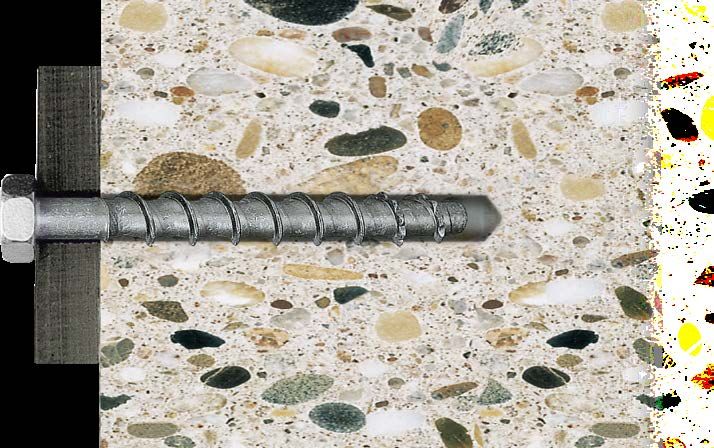
7
LEONI – the all-in-one service provider
For infrastructure, energy and ICT
Energy and ICT infrastructure
Consulting Planning Execution Operations
Consulting
Design/development
Planning
Sole contractor services
Main contractor services
Other services
LEONI products
Excellence in operations
Energy efficiency Sustainability Innovation Quality
LEONI’s department Building Technologies is an innovative With its highly focused service portfolio, LEONI can offer you
and independent supplier of sustainable all-in-one solu- additional services to optimise your long-term capital invest-
tions for energy and ICT infrastructure to the international ment and operating costs.
market.
Building Technologies offers the perfect combination of
In any project, being able to keep the demands of the various ■■ cable manufacturer,
stakeholder groups in balance is critical for project success. ■■ engineering company,
Each of these stakeholders is focused on its own competencies ■■ plant integrator and
and task areas, however. ■■ service provider.
As a consequence, the client or owner is required to orchestrate It is this combination that enables the unit to handle the com-
these complex interrelationships and keep an eye on everything. plex requirements customers face both today and tomorrow.
This is where LEONI can help by ensuring the optimal coordina-
tion of the various subject areas, bringing together industry-wide We create solutions for you that offer all-round satisfaction.
know-how under one roof, in a team staffed by engineers,
technical architects, security consultants and construction
supervisors. A well-developed project management system and
tailor-made software tools provide a high degree of plannability,
resulting in important cost savings in the implementation phase, Phone +41 62 288 82 82
with a significantly reduced level of project risk. E-mail building-technologies@leoni.com
03/2019 www.leoni-energy-infrastructure.com
8

Green Technology
Combining innovation with sustainability. It’s one of our most important goals.

Our vision is to create sustainable connections that are in tech-     More and more facilities
nological harmony with our natural resources. The natural cycle       in our global production
offers us the perfect model to emulate here. It is our duty to        network are now environ-
learn from nature – to use its resources even as we conserve          mentally certified to the
them for future generations. As natural resources grow scarcer        ISO 14001 standard.
and the burden on the environment increases, a rethink is
required at all levels of our society. For LEONI, sustainability      In our worldwide operations as a leading European supplier of
is therefore an integral part of Group policy. We were the first      wires, optical fiber, cables and cable systems for communication
cable manufacturer in the world to develop an integrated ‘green       and infrastructure projects, it is our responsibility to continu-
technology’ programme.                                                ously optimise the sustainability and durability of our products,
                                                                      system solutions and services, so as to reduce their impact on
While trends such as globalisation, mobility and urbanisation         the environment. We have to increase the amount of environ-
are crucial for market movements, our core principles are sus-        mentally compatible raw materials in our cable products as
tainability and global responsibility. This is why we have set our-   well as the recyclability of processed materials or components,
selves the goal of becoming an innovative producer of cables for      thereby creating end products that have been developed today
ecotechnology. Another point of vital interest for us is to iden-     for the environmental standards of tomorrow.
tify the needs and requirements of tomorrow today, and to sup-
ply the markets of the future with future-proof and sustainable       Together with ecological compatibility, future technologies are
solutions. We also view it as our responsibility to take an active    measured in terms of efficiency, service life, emission reduction
role in shaping the markets for environmentally-friendly energy       and the conservation of natural resources. Innovative cable
production – such as solar thermal technology.                        products and systems, integrated solutions and maximum
                                                                      performance in project management make up the added value
Green technology refers to producing cables from materials            that we offer to our customers and business partners, while also
with very few pollutants while conserving resources and gener-        being our cornerstones for ensuring strong connections into the
ating low levels of emissions. We work tirelessly on optimising       future.
the efficiency of resource use in the manufacturing process,
by deploying energy-efficient machines or implementing heat
recovery technologies.

                                                                                                  www.leoni-energy-infrastructure.com   03/2019
9
EU Directive 2012/19/EU on waste electrical and elec-
tronic equipment.
EU Directive 2011/65/EU on the restriction of the use
of certain hazardous substances in electrical and elec-
tronic equipment.
EU Regulation 1907/2006/EC (REACH) – the EU chemicals
regulation.
Several environmental laws have been passed in the European
Union (EU). Directive 2012/19/EU WEEE (Waste Electrical and
Electronic Equipment) regulates the disposal of electrical and
electronic equipment and components. The use of certain
hazardous substances in electrical and electronic equipment
is regulated by Directive 2011/65/EU RoHS 2 (Restriction of
Hazardous Substances). Chemicals and substances in general
are covered by Regulation 1907/2006/EC REACH (Registration,
Evaluation, Authorisation and Restriction of Chemicals).
This means avoiding substances such as:
■■ Polybrominated diphenyl ether (PBDE)
■■ Decabromodiphenyl ether (DecaBDE)
■■ Perfluorooctane sulfonate (PFOS)
■■ Pentabromodiphenyl ether (PentaBDE)
■■ Octabromodiphenyl ether (OctaBDE)
■■ Lead (Pb)
REACH
■■ Mercury (Hg)
■■ Cadmium (Cd)
■■ Hexavalent chromium (Cr VI) What is REACH?
■■ Polybrominated biphenyls (PBB)
REACH stands for the Registration, Evaluation, Authorisa-
Cables, wiring and their associated connectors are governed by tion and Restriction of Chemicals.
the EU WEEE Directive (2012/19/EU) only if they are an internal
part of the equipment and components listed. REACH represents a fundamental harmonisation and
simplification of previous chemicals law and applies in
Cables and wiring have been regulated separately in RoHS 2 all EU Member States.
(2011/65/EU) since 2013 (Category 11 or defined as an internal
component of the respective product). Fiber-optic cables, REACH introduced a ‘candidate list’ for materials
energy cables (> 250 V) and permanently installed cables (e.g. known as Substances of Very High Concern (SVHC):
in buildings) are not affected. The only identification permis- certain duties of providing information apply to SVHCs
sible according to RoHS 2 is the CE mark, which is printed on the and the aim is to phase them out in favour of other
product package. materials in the future. The list of candidate substances
is updated twice yearly by the European Chemicals
Agency (ECHA) in Helsinki.
03/2019 www.leoni-energy-infrastructure.com
10

                  EU Construction Products Regulation (CPR)
                  On the safe side with LEONI fire resistant cables

           CPR

      B2ca                  Since 1 July 2017, all energy cables, control cables and communications
       Cca                  cables intended for permanent installation in building structures must
       Dca                  be manufactured and evaluated in accordance with the harmonised
                            European standard EN 50575 and labelled with a CE mark pursuant to
       Eca
                            the EU Construction Products Regulation 305/2011.
       Fca
CPR cable class

                  In addition, a ‘declaration of performance’ must also be prepa-      EN 50575 does not specify which class must be used in which
                  red on the basis of assessments and classifications carried out      building or which part of a building (e.g. for escape routes).
                  by an accredited and notified testing body. A key element of the     The German Electrical and Electronic Manufacturers’ Association
                  CE marking and declaration of performance prescribed by the          (ZVEI) has published a building classification.
                  Regulation is the highly visible, legible and permanent specifi-
                  cation of the fire rating as provided on the product label.          For buildings with very high safety requirements, such as hos-
                                                                                       pitals, fire-resistant cables are envisaged with a B2ca s1 d1 a1
                  LEONI offers fire resistant cables with reduced flame propaga-       Euroclass. For buildings with high safety requirements, such
                  tion and heat production while also ensuring the low release of      as schools, fire resistant cables with a Cca s1 d1 a1 Euroclass
                  corrosive gases and smoke in accordance with the Regulation.         should be used. For normal fire risks, cables with a Dca s2 d2 a1
                                                                                       Euroclass are adequate.
                  The CPR defines a set of fire ratings (cable classes) that range
                  from Aca (incombustible) through B2ca (very high fire protection),   Declaration of Performance (DoP)
                  Cca, Dca, Eca to Fca (no fire protection).                           This declaration of performance confirms the conformity of the
                                                                                       construction product with the specified fire resistance properties.
                  Alongside the fire ratings, the following properties are also        In this area, you can download the declarations of performance
                  specified:                                                           for the LEONI cable and wiring products that can be used as con-
                  ■■   Smoke production (s1 to s3)                                     struction products.
                  ■■   Acid gas (a1 to a3)                                             Simply enter the declaration of performance ID to access the
                  ■■   Flaming droplets (d0 to d2)                                     declaration of performance you need directly.
                                                                                       The declaration of performance ID is printed on the CE label of
                                                                                       your product or can also be found by consulting your quotation
                                                                                       or order documentation.
                                                                                                                                    www.leoni.com/en/cpr/

                                                                                                                 www.leoni-energy-infrastructure.com   03/2019
11
Technologies – investments in sustainable safety
Universal deployment with system integrity
In our extensive production facilities, we work
with state-of-the-art methods and systems in
compound and material processing, extrusion
technology, electron beam irradiation crosslinking
and for testing all of our products.
We use state-of-the-art production equipment to ensure that
■■ Halogen-free IEC 60754-1, EN 60754-1
we can offer our customers the highest possible levels of prod-
uct safety and quality. New and innovative polymer compounds
■■ Acidity of combustion gases
and cables are in continuous development in our modern labo-
IEC 60754-2, EN 60754-2
ratories. Our focus here is on improved insulating properties,
higher temperature tolerances, longer lifetimes, easy handling
■■ Smoke density IEC 61034, EN 61034
and better safety features.
Our test laboratories for flammability tests, HF technology and ■■ Flame retardancy
optical measurement technology safeguard our quality stand- IEC 60332-1, EN 60332-1, VDE 0482-332-1
ards and promote innovation.
■■ Circuit integrity
This is demonstrated by the large number of approvals and BS 6387 (CWZ), DIN VDE 0472-814, EN 50200, EN 50362,
certificates we have received from leading independent testing IEC 60331-11/21, VdS 3423, VDE 0482-200
institutes worldwide.
■■ System integrity under fire DIN 4102 Part 12
In our fire test laboratory, the fire resistant properties of our
products are verified by certified testers, technicians and engi- ■■ Non-flame propagating
neers. These capabilities allow us to perform the wide-ranging IEC 60332-3, EN 60332-3, VDE 0482-332-3 series
testing required to comply with BS 6387 (CWZ), IEC 60331-11/21
and DIN 4102 Part 12, as well as customer-specific specifications ■■ CPR fire behaviour
and special testing work. EN 50399, EN 50575
Numerous national and international certificates provide proof
of our company’s power to innovate.
Numerous national and international certificates confirm the company’s ability to provide innovative solutions.
03/2019 www.leoni-energy-infrastructure.comBETAfixss® 12 Laying systems
BETAfixss® laying systems overview
DIN 4102 part 12 (E30 / E90)
■■ BETAfixss® WSB XL
page 18
3000 mm
mounting distance
■■ BETAfixss® GK ■■ BETAfixss® STR
page 24 page 28
1500 mm
mounting distance
■■ BETAfixss® ES / GSM ■■ BETAfixss® RES ■■ BETAfixss® BAC
page 30 page 32 page 33
1200 mm
mounting distance
■■ BETAfixss® ES / GSM ■■ BETAfixss® BAC ■■ BETAfixss® Insta-Clic
page 30 page 33 page 37
800 mm
mounting distance
■■ BETAfixss® F / RF
page 44
600 mm
mounting distance
www.leoni-energy-infrastructure.com 03/2019BETAfixss® laying systems overview Laying systems 13 BETAfixss®
■■ BETAfixss® AVS ■■ BETAfixss® VT
page 46 page48
new
■■ BETAfixss® RBS ■■ BETAfixss® KAH ■■ BETAfixss® UP
page 35 page 45 page 49
■■ BETAfixss® DWS ■■ BETAfixss® BSD ■■ BETAfixss® HMS / MMS
page 40 page 50 page 54
■■ BETAfixss® SHX
page 42
new
03/2019 www.leoni-energy-infrastructure.comBETAfixss® 14 Laying systems
BETAfixss® mounting and installation conditions
The application of the approved cables is based System Dimensions Mounting distance
on the test certificates from the Material Testing
Office (MPA) respectively on the expertise and mm mm
its details of laying. With reservation of amend-
WSB XL spantray ≤ 500 × 60 ≤ 3000
ments or technical alternations.
STR Vertical riser with BAC clamp ≤ 400 × 60 ≤ 1500
Specifications of cross section restrictions refer
to the single conductors only. Conduit mesh tray
GK ≤ 100 × 150 ≤ 1500
with safety clip
≤ Ø 63 ≤ 800
ES Single clamp M6
≤ Ø 63 ≤ 1200
≤ Ø 78 ≤ 800
GSM Joint clamp M8
≤ Ø 78 ≤ 1200
≤ Ø 76 ≤ 800
U-clamp without long trough
BAC
mounted on system track
≤ Ø 76 ≤ 1200
≤ Ø 78 ≤ 1200
RBS / RES Halogen free plastic tube
≤ Ø 78 ≤ 1200
≤ Ø 78 ≤ 1200
RBS / RES Reinforced steel tube
≤ Ø 78 ≤ 1200
Ceiling wall hanger
DWS ≤ 70 × 120 ≤ 800
with safety clip
Insta-Clic Holder, duct ≤ 70 × 20 ≤ 800
F / RF Single clamp ≤ Ø 45 ≤ 600
AVS
Branch- & ne u ≤ 200 × 200
connection system
VT Plastic distributor ≤ 175 × 250
KAH Cable support ≤ 150× 200 × 920
Concealed installation with a
UP ≤ 1500
mineral plaster layer of ≤ 15 mm
SHX Collecting clamp ne u ≤ 54 × 81 ≤ 800
www.leoni-energy-infrastructure.com 03/2019BETAfixss® assembly and laying conditions Laying systems 15 BETAfixss®
Load Single laying Multiple laying Classification Horizontal Transversal Vertical
BETAflam® cable BETAflam® cables installation installation installation
(ceiling/wall)
mm Ø mm Ø DIN 4102-12
≥ 1.5 mm² ≥ 1.5 mm² E30 / E90
≤ 20 kg / m
≥ n × 2 × 0.8 ≥ n × 2 × 0.8 E30 / E90
≥ 1.5 mm² ≥ 1.5 mm²
≤ 20 kg / rung E30 / E90
≥ n × 2 × 0.8 ≥ n × 2 × 0.8
≥ 1.5 mm² ≥ 1.5 mm²
≤ 10 kg / m E30 / E90
≥ n × 2 × 0.8 ≥ n × 2 × 0.8
≥ 1.5 mm² ≤ 10 mm² ≤ 3 cables
≤ 7.5 kg clamp E30 / E90
≥ n × 2 × 0.8 ≤ 32 × 2 × 0.8 ≤ 3 cables
≥ 1.5 mm² ≥ 1.5 mm²
≤ 2.5 kg clamp E30 / E90
≥ n × 2 × 0.8 ≥ n × 2 × 0.8
≥ 1.5 mm² ≤ 10 mm² ≤ 3 cables
≤ 7.5 kg clamp E30 / E90
≥ n × 2 × 0.8 ≤ 52 × 2 × 0.8 ≤ 3 cables
≥ 1.5 mm² ≥ 1.5 mm²
≤ 2.5 kg clamp E30 / E90
≥ n × 2 × 0.8 ≥ n × 2 × 0.8
≤ 50 mm² ≤ 3 cables
≥ 1.5 mm²
≤ 7.5 kg / clamp ≤ 52 × 2 × 0.8 ≤ 5 cables E30 / E90
≥ n × 2 × 0.8
≥ 1.5 mm² ≤ 4 single cores
≥ 1.5 mm² ≥ 1.5 mm²
≤ 2.5 kg / clamp E30 / E90
≥ n × 2 × 0.8 ≥ n × 2 × 0.8
≤ 50 mm² ≤ 50 mm² ≤ 3 cables
≤ 10 kg / m E30 / E90
≤ 52 × 2 × 0.8 ≤ 52 × 2 × 0.8 ≤ 3 cables
≥ 1.5 mm² ≥ 1.5 mm²
≤ 2.5 kg / clamp E30 / E90
≥ n × 2 × 0.8 ≥ n × 2 × 0.8
≥ 1.5 mm² ≥ 1.5 mm²
≤ 10 kg / m E30 / E90
≥ n × 2 × 0.8 ≥ n × 2 × 0.8
≥ 1.5 mm² ≥ 1.5 mm²
≤ 2.5 kg / clamp E30 / E90
≥ n × 2 × 0.8 ≥ n × 2 × 0.8
≤ 50 mm² ≤ 50 mm²
≤ 10 kg / clamp E30 / E90
≤ 52 × 2 × 0.8 ≤ 52 × 2 × 0.8
≤ 10 mm² ≤ 10 mm²
E30 / E90
≥ n × 2 × 0.8 ≥ n × 2 × 0.8
≤ 16 mm²
E30 / E90
≥ n × 2 × 0.8
≤ 16 mm²
E30 / E90
≥ n × 2 × 0.8
≥ 1.5 mm² ≥ 1.5 mm²
E30
≥ n × 2 × 0.8 ≥ n × 2 × 0.8
≥ 1.5 mm² ≥ 1.5 mm² ≤ 2 cables
E30 / E90
≥ n × 2 × 0.8 ≥ n × 2 × 0.8 ≤ 2 cables
≤ 5 kg / m E0
03/2019 www.leoni-energy-infrastructure.comBETAfixss® 16 Laying systems
BETAflam® / BETAfixss® approvals
Usage Note:
BETAfixss support systems are used for electrical cable systems
®
Specifications are valid at the time
with system integrity. They also guarantee the fireproof mount- of publishing.
ing of cables installed in the area between floor slabs and F30 or
F90 suspended ceilings.
BETAflam® approvals
MPA NRW Dortmund, Germany
Product group Valid to Approval no. Classification
BETAflam NHXH E30–E60 S
® 27/ 02/2022 P-MPA-E-05-008 E30, E60
BETAflam NHXH E30–E60
®
27/ 02/2022 P-MPA-E-05-008 E30, E60
BETAflam® NHXCH E30–E60 27/ 02/2022 P-MPA-E-05-008 E30, E60
BETAflam JE-H(St)H E30
® 27/ 02/2022 P-MPA-E-05-008 E30
BETAflam® JE-H(St)HRH E30 27/ 02/2022 P-MPA-E-05-008 E30
BETAflam NHXH E90
®
27/ 02/2022 P-MPA-E-05-008 E90
BETAflam® NHXCH E90 27/ 02/2022 P-MPA-E-05-008 E90
BETAflam JE-H(St)H E30–E90
®
27/ 02/2022 P-MPA-E-05-008 E30, E60, E90
BETAflam® JE-H(St)HRH E30–E90 27/ 02/2022 P-MPA-E-05-008 E30, E60, E90
BETAflam JE-H(St)H E30 SIR
®
27/ 02/2022 P-MPA-E-05-008 E30, E60
BETAflam® JE-HH FE180/E30 S 01/ 12/2021 P-MPA-E-15-011 E30, E60
BETAflam with quick laying system and branch boxes
® 01/ 12/2021 P-MPA-E-15-011 E30, E60, E90
BETAflam® approvals
VdS Schadenverhütung GmbH, Cologne, Germany
Product group Valid to Approval no. Classification
BETAflam® NHXH E90 ≥ 2.5 mm2 21/07/2020 G 4980033 E90
BETAflam NHXCH E90 ≥ 2.5 mm
® 2
21/07/2020 G 4980034 E90
BETAflam® approvals
with other support system manufacturers
MPA NRW Dortmund, Germany
Supplier Valid to Approval no. Classification
OBO Bettermann 31/07/2021 P-MPA-E-05-030 E30, E60, E90
PUK-Werke 31/07/2021 P-MPA-E-05-030 E30, E60, E90
PUK-Werke 20/11/2021 P-MPA-E-16-013 E30, E60, E90
RICO GmbH 31/07/2021 P-MPA-E-05-030 E30, E60, E90
NIEDAX GmbH & Co. KG 31/07/2021 P-MPA-E-05-030 E30, E60, E90
HILTI Deutschland GmbH 31/07/2021 P-MPA-E-05-030 E30, E60, E90
www.leoni-energy-infrastructure.com 03/2019BETAflam® / BETAfixss® approvals Laying systems 17 BETAfixss® Approvals of other support system manufacturers with BETAflam® cables Supplier Approval Classification Spelsberg Small distributors E30, E60 Celsion, Rodgau, Germany Distributors, cabinets E30, E60 OBO Bettermann Cable racks, stainless steel mesh racks E30, E60, E90 OBO Bettermann LKM cable routing ducts, cable junction boxes, cable holders E30, E60, E90 BETAflam® approval on cable trays without threaded rod support Supplier Approval no. Classification LEONI Studer AG XL wide-span track P-MPA-E-05-008 E30, E60, E90 OBO Bettermann Cable rack RKSM 610 … 640 P-MPA-E-13-002 E30, E60, E90 PUK-Werke Cable rack RG 60 – XX P-MPA-E-16-013 E30, E60, E90 NIEDAX GmbH & Co. KG Cable rack RLVC 60.100 –400 P-MPA-E-16-011 E30, E60, E90 VergoKan Cable rack KBSI P-MPA-E-14-007 E30, E60, E90 Cables with integrated system integrity Please note that the system integrity according to DIN 4102-12 is guaranteed only if appropriate fixation systems are used, and these systems are installed according to the provisions of the valid DIN test certificates and/or the ‘expert opinions’. The LEONI BETAflam® and BETAfixss® products satisfy this requirement and we therefore recommend their use. Identification plate After installing a cable system with system circuit according to DIN 4102 part 12, the system must be identified with an ID plate. 03/2019 www.leoni-energy-infrastructure.com
BETAfixss®         18   Laying systems                                                                                                          BETAfixss® WSB

             XL spantray
             20 kg/m, E30 / E90

                                                                                                                        Competitive advantage

                                                                                                                        ■■   3000 mm mounting distance
                                                                                                                             permitted, every second ceiling
                                                                                                                             pillar is dispensable
                                                                                                                        ■■   Symmetrical centre fixation,
                                                                                                                             no disruptive threaded rods
                                                                                                                        ■■   Future-proof and always
                                                                                                                             expandable, cascading extender
                                                                                                                             brackets
                                                                                                                        ■■   When there are no reliable fixa-
                                                                                                                             tion points, the spantray covers
                                                                                                                             the distances

                                         ≤ 30 0 0
                                                    mm

                  BETAfixss® WSB

             Application
             For single and multiple laying of BETAflam® cables E30 / E90
             on ceilings or walls with very large spans.

             ■■   A maximum of 3 tracks per ceiling pillar is permitted

             Material
             ■■   Galvanized steel

              System                        Dimensions   Mounting distance   Load     Single laying *   Multiple laying *      Classification   Approvals

                                            mm           mm                  kg / m   mm Ø              mm Ø                   DIN 4102-12
              WSB                                                                     ≥ 1.5 mm2         ≥ 1.5 mm2                               Test certificate
                                            ≤ 400 × 60   ≤ 3000              ≤ 20                                              E30 / E90
              Wall mounting                                                           ≥ n × 2 × 0.8     ≥ n × 2 × 0.8                           from MPA NRW
              WSB
                                                                                      ≥ 1.5 mm2         ≥ 1.5 mm2                               Test certificate
              Ceiling mounting              ≤ 500 × 60   ≤ 3000              ≤ 20                                              E30 / E90
                                                                                      ≥ n × 2 × 0.8     ≥ n × 2 × 0.8                           from MPA NRW
              1 to 3 layer
              * exception NHXCH FE180/E90

                                                                                                                www.leoni-energy-infrastructure.com     03/2019
BETAfixss® WSB Laying systems 19 BETAfixss®
XL spantray
20 kg/m, E30 / E90
WSST 500
for 2nd and
3rd layer
WSST 250
for 1st layer
WSB XL Spantray DST-8 Ceiling pillar WSST Extender
Section length 3 metres 8-hole bracket
Type Dimen- Rung Order no. Type Dimensions Order no. Type Dimensions Order no.
sions distance
mm PU: 1 piece mm PU: 1 piece
mm mm PU: 3 m
DST-8 200 50 × 50 × 200 314278 WSST 250 250 × 50 × 45 314284
WSB 200 200 × 60 300 314342
DST-8 300 50 × 50 × 300 314277 WSST 500 500 × 56 × 45 314283
WSB 300 300 × 60 300 314343
DST-8 400 50 × 50 × 400 314276
WSB 400 400 × 60 300 314344
DST-8 500 50 × 50 × 500 314275
WSB 500 500 × 60 300 314345
DST-8 600 50 × 50 × 600 314274
DST-8 700 50 × 50 × 700 314273
DST-8 800 50 × 50 × 800 314272
DST-8 900 50 × 50 × 900 314271
DST-8 1000 50 × 50 × 1000 314270
DST-8 1200 50 × 50 × 1200 314269
DST-8 1500 50 × 50 × 1500 314268
DST-8 2000 50 × 50 × 2000 314267
Spacer tube
Flanged screw Flanged nut
SGST Screw kit WSD Cover WSDH Fixing clamp
for WSD cover
Type Dimensions Order no. Type Dimensions Order no. Type Dimensions Order no.
mm PU: 1 piece mm PU: 1 piece mm PU: 10 pieces
SGST 250 M10 × 70 314214 WSD 200 200 × 3000 314341 WSDH 60 on request
SGST 500 M10 × 80 314402 WSD 300 300 × 3000 314340
SGST 250 ➔ connects expander bracket 250 WSD 400 400 × 3000 314339
to ceiling pillar WSD 500 500 × 3000 314338
SGST 500 ➔ for the fixation of additional
expander bracket 500 on the top layer
03/2019 www.leoni-energy-infrastructure.comBETAfixss® 20 Laying systems BETAfixss® WSB
XL spantray
20 kg/m, E30 / E90
SS System rail US U-rail
toothed for inner reinforcement of SS and SKO
Type Dimensions Order no. Type Dimensions for SS for SKO Order no.
mm PU: 1 piece mm mm mm PU: 1 piece
SS 250 50 × 50 × 250 314295 US 150 44 × 44 × 150 350 350, 450 314683
SS 350 50 × 50 × 350 314680 US 250 44 × 44 × 250 450 314282
SS 450 50 × 50 × 450 314298 US 350 44 × 44 × 350 550 314684
SS 550 50 × 50 × 550 314300
Washer
Flanged nut
Flanged nut
Hammer head screw
Flanged screw
HSMG Screw kit FSMG Screw kit SKO Heavy-duty console
Hammer head
Type Dimensions Order no. Type Dimensions Order no. Type Dimensions Order no.
mm PU: 1 piece mm PU: 1 piece mm PU: 1 piece
HSMG M10 × 20 314211 FSMG M10 x 20 314357 SKO 250 50 × 50 × 250 314285
Centre screw connects the 250 mm system track Centre screw connects the system track SKO 350 50 × 50 × 350 314286
(only with WSB 200) to the expander bracket. (and U-rail) to the expander bracket SKO 450 50 × 50 × 450 314287
www.leoni-energy-infrastructure.com 03/2019BETAfixss® WSB Laying systems 21 BETAfixss®
XL spantray
20 kg/m, E30 / E90
KML Clamping strap WST T-section WSSK Protective cap
for consoles for fastening of WSB for WSB
Type Dimensions Order no. Type Dimensions Order no. Type Version Order no.
PU: 25 pieces mm PU: 1 piece PU: 1 piece
KML M6 314523 WST 200 200 314688 WSSK L left 314514
WST 300 300 314687 WSSK R right 314515
WST 400 400 314686 Halogen-free plastic, yellow
WST 500 500 314685
WSSV / WSWV / WSGV Connectors
Type Dimensions Order no.
mm PU: 1 piece
WSS Side connector 40.5 × 21 × 300 314501
WSWV Angle connector 40.5 × 21 × 300 314526
WSGV Joint connector 40.5 × 21 × 360 314527
03/2019 www.leoni-energy-infrastructure.comBETAfixss® 22 Laying systems BETAfixss® WSB
BETAfixss® WSB overview
DST-8 ceiling pillar WSDH fixing clamp
SGST 250 screw kit
WSST 250 expander bracket
KML clamping strap WSD cover
WSB XL spantray
WSSV side connector
SS system rail
US U-rail
WSST 500 expander bracket
HSMG screw kit WSST 500 expander bracket SGST 500 screw kit
Hammer head
WSB XL Spantray WSD Cover WSDH Fixing clamp
7 x 15
25 40
12 x 35
25
41
0
0 30 0
12
30 A
M6
63
30
0
3 000
B
150
DST-8 Ceiling pillar WSST Extender bracket 56 45
15 35 7.5
150
150 100 50 45
10 0
15 35 7.5
11 x 30
500
250
35 15
25 25 25
11 x 35
57
L
32.5 35 15
11 x 35 11 x 16.5
50
50
11 x 16.5
www.leoni-energy-infrastructure.com 03/2019BETAfixss® WSB Laying systems 23 BETAfixss®
WSS Side connector SGST Screw kit
30 0
8 0
70/
/49
44
10 0
25 M1
0
M1 0
40.5
25 x 12
21
2.5
HSMG Hammer head screw kit FSMG Screw kit KML Clamping strap
M6 x 25
20
43 45
20
M1
0 M1
0
23
SS System track US U-rail
L
44
L
50
44
50
WST T-section
SKO Heavy-duty console
13x20 (3x)
B
55 25
L B
0+
140
63
200
11x16.5
R5
20 0 B
21x21
20 0
00
03/2019 www.leoni-energy-infrastructure.comBETAfixss® 24 Laying systems BETAfixss® GK
Conduit mesh tray
E30 / E90
Competitive advantage
■■ Approved safety
■■ The most economical type of
multiple laying for up to 10 kg/m
rated load and up to 1500 mm
■■ Total system integrity
■■ Problem-free retrofitting
■■ Horizontal and transversal
laying
≤ 1500
mm
BETAfixss® GK
Application
For single and multiple laying of BETAflam® cables E30 / E90
on ceilings or walls.
■■ The mesh tray is coated with halogen-free plastic
■■ The most economical type of multiple laying
for up to 10 kg/m rated load
■■ Anchor distance with hook rail ≤ 200 mm
■■ The safety clip must be attached every 800 mm
■■ Bends can be routed openly
■■ A maximum of 4 mesh trays per hook rail pillar are permitted
Material
■■ Plastic-coated steel
System Dimensions Mounting distance Load Single laying * Multiple laying * Classification Approvals
mm mm kg / m mm Ø mm Ø DIN 4102-12
GK ≥ 1.5 mm2 ≥ 1.5 mm2 Test certificate
≤ 100 × 150 ≤ 1500 ≤ 10 E30 / E90
Conduit mesh tray ≥ n × 2 × 0.8 ≥ n × 2 × 0.8 from MPA NRW
* Exceptions
JE-H(St)HRH FE180/E30-E90 Distance ≤ 800 mm E90
Distance ≤ 1500 mm E30, E60
www.leoni-energy-infrastructure.com 03/2019BETAfixss® GK Laying systems 25 BETAfixss®
Conduit mesh tray
E30 / E90
GK Conduit mesh tray HKS-St Hook rail, standard HKS-S Hook rail support
for screws up to Ø 7 mm
Type Dimensions Open- Order no. Type Dimensions Order no. Type Dimensions Order no.
ing
mm (L × W) PU: 12 pieces mm (L × W) PU: 1 piece
mm mm PU: 1 piece
HKS-St 05 50 × 25 314511 HKS-S 1 100 × 50 314445
GK 50 × 50 × 1955 16 314498
HKS-St 07 75 × 25 314510 HKS-S 2 200 × 50 314444
GK 50 × 75 × 1955 20 314497
HKS-St 12 125 × 25 314509 HKS-S 3 300 × 50 314443
GK 50 × 100 × 1955 20 314496
HKS-St 20 200 × 25 314508 HKS-S 4 400 × 50 314442
GK 75 × 100 × 1955 35 314495
HKS-St 30 300 × 25 314507 HKS-S 5 500 × 50 314441
GK 75 × 125 × 1955 35 314494
mm (L × W) PU: 1 piece
GK 100 × 150 × 1955 45 314493
HKS-St 200 2000 × 25 314506
HKS-G Large hook rail SCGK Safety clip KDS Plastic resin spray
for screws up to Ø 12 mm for mesh tray for mesh tray
Type Dimensions Order no. Type Dimen- Open- Order no. Type Quantity Colour Order no.
sions ing
mm (L × W) PU: 10 pieces g PU: 1 piece
mm mm PU: 25 pieces
HKS-G 10 100 × 50 314505 KDS 150 light grey 314434
SCGK
HKS-G 20 200 × 50 314504 50 × 50 16 314438
16/26
HKS-G 30 300 × 50 314503 SCGK 50 × 75
20 314437
20/39 50 × 100
mm (L × W) PU: 1 piece
SCGK 75 × 100
HKS-G 100 400 × 50 314502 35 314436
35/49 75 × 125
SCGK
100 × 150 45 314435
45/59
VBL Linking strap GKV Mesh tray BLB Blockade plate GKK G Tray clamp
Corner connector, screw-in connector for HKS-S and HKS-G for direct ceiling and
Joint connector, screw-in wall fixation
Type Order no. Type Order no. Type Order no. Type Order no.
PU: 25 pieces PU: 25 pieces PU: 1 piece PU: 25 pieces
VBL 314440 GKV 314439 BLB 314433 GKK 314383
03/2019 www.leoni-energy-infrastructure.comBETAfixss® 26 Laying systems BETAfixss® GK
Conduit mesh tray E30 / E90 overview
GK 50 × 50 GK 50 × 75 GK 50 × 100
GK 75 × 100 GK 100 × 150
GK 50 × 50
GK 50 × 75
GK 50 × 100
www.leoni-energy-infrastructure.com 03/2019BETAfixss® GK Laying systems 27 BETAfixss® HKS-S Hook rail support HKS-St Standard hook rail HKS-G Large hook rail GK Conduit mesh tray VBL Linking strap GKV Mesh tray connector SCGK Safety clip GKK G tray clamp 03/2019 www.leoni-energy-infrastructure.com
BETAfixss®         28    Laying systems                                                                                                                    BETAfixss® STR

             Vertical riser
             E30 / E90

                                                                                                                                   Competitive advantage

                                                                                                                                   ■■   Approved safety
                                                                                                                                   ■■   Total system integrity
                                                                                                                                   ■■   Stackable multitrays
                                                                                                                                        (cost-saving storage/
                                                                                                                                        transportation)

                  BETAfixss® STR

             Application                                                                    Material
             For vertical single and multiple laying of BETAflam® cables E30 /              ■■   Galvanized steel
             E90 with total system integrity during a fire on ceilings or walls.
                                                                                            Accessories
             ■■   This component is used together with U-clamps                             Connector, vertical riser wall clamp, angle, U-clamp, dowel and
             ■■   The distances of the U-clamps are ≤ 750 mm                                additional accessories parts must be ordered separately.
             ■■   Vertical risers in standard length 3 m
             ■■   Standard widths 100, 200, 300 and 400 mm                                       Our service
             ■■   Usable width = standard width less than 60 mm
                                                                                                 LEONI helps you find the right solution for your cable
             ■■   Can be mounted parallel to the wall in riser zones
                                                                                                 installation work and in obtaining any required special
             ■■   Perforations 12 x 35 mm (for fixation of the vertical riser wall
                                                                                                 approvals.
                  clamps) in the following distances (starting at the bottom):
                  75 mm / 600 mm / 600 mm / 450 mm / 600 mm / 600mm

              System            Dimensions         Mounting distance   Load                Single laying       Multiple laying          Classification    Approvals

                                mm                 mm                  kg                  mm Ø                mm Ø                     DIN 4102-12
                                                                                                               ≤ 50 mm2
                                                                                                               ≤3 cables

              STR                                                      ≤ 20 kg/rung        ≥ 1.5 mm2           ≤ 52 x 2 0.8                               Test certificate
                                ≤ 400 × 60         ≤ 1500                                                                               E30 / E90
              Vertical riser                                           ≤ 7.5 kg / clamp*   ≥ n × 2 × 0.8       ≤5 cables                                  from MPA NRW

                                                                                                               Single-wire
                                                                                                               ≤4 cables
                                                                       ≤ 20 kg/rung        ≥ 1.5 mm2           ≥ 1.5 mm2                                  Test certificate
                                ≤ 400 × 60         ≤ 1500                                                                               E30 / E90
                                                                       ≤ 2.5 kg / clamp    ≥ n × 2 × 0.8       ≥ n × 2 × 0.8                              from MPA NRW
              * No limitation for single laying.

                                                                                                                           www.leoni-energy-infrastructure.com     03/2019
BETAfixss® STR Laying systems 29 BETAfixss®
Vertical riser
E30 / E90
MB Multitray VBU 60 Connector, universal SWB Vertical riser wall clamp
Section length 3 metres incl. screw kit M6 x 10
Type Dimen- Rung Order no. Type Length Order no. Type incl. screw kit Order no.
sions distance
mm PU: 50 pieces PU: 1 piece
mm mm
VBU 60 275 314475 SWB M10 × 25 314516
MB 100 100 × 60 75 314337
For straight or angled connections of the rail.
MB 200 200 × 60 75 314336 2 units per joint required.
MB 300 300 × 60 75 314418
MB 400 400 × 60 75 314500
BAC U-clamp BAC U-clamp / 2 BAC U-clamp / 3
BAC U-clamp
for cable fixation
Type for cable PU Order no. Type for cable PU Order no. BAC U-clamp
Ø mm Unit Ø mm Unit
BAC 8-12 8 – 12 250 314163 BAC 8-12 / 2 8 – 12 250 314147 VBU 60 connector,
universal
BAC 12-16 12 – 16 250 314162 BAC 12-16 / 2 12 – 16 250 314148
BAC 16-20 16 – 20 250 314161 BAC 16-20 / 2 16 – 20 250 314149
BAC 20-24 20 – 24 250 314160 BAC 20-24 / 2 20 – 24 250 314150
BAC 24-28 24 – 28 250 314159 BAC 24-28 / 2 24 – 28 250 314151
SWB
BAC 28-32 28 – 32 200 314158 BAC 28-32 / 2 28 – 32 100 314152 Wall clamp
BAC 32-36 32 – 36 200 314157 BAC 32-36 / 2 32 – 36 100 314141
BAC 36-40 36 – 40 200 314156 BAC 36-40 / 2 36 – 40 100 314168
BAC 40-44 40 – 44 100 314155 BAC 40-44 / 2 40 – 44 100 314195
BAC 44-48 44 – 48 100 314154 BAC 44-48 / 2 44 – 48 100 314194
BAC 48-52 48 – 52 100 314153 BAC 48-52 / 2 48 – 52 100 314193
BAC 52-56 52 – 56 100 314152 BAC 52-56 / 2 52 – 56 100 314192
BAC 56-60 56 – 60 100 314151
BAC 60-64 60 – 64 50 314150 BAC 8-12 / 3 8 – 12 250 134191 MB multitray
BAC 64-70 64 – 70 50 314149 BAC 12-16 / 3 12 – 16 250 134190
BAC 70-76 70 – 76 50 314148 BAC 16-20 / 3 16 – 20 250 134189
BAC 20-24 / 3 20 – 24 100 134188
BAC 24-28 / 3 24 – 28 100 134187
03/2019 www.leoni-energy-infrastructure.comBETAfixss® 30 Laying systems BETAfixss® ES / GSM
Single clamp and joint clamp
E30 / E90
Competitive advantage
■■ Clear savings in comparison with
standard installation according
to DIN 4102-12
■■ Multi-bundling approved,
number of cables not restricted
■■ Horizontal, transversal and
vertical installation
≤ 1200 m
m
BETAfixss® ES / GSM
Application
For horizontal, transversal and vertical single or multiple laying
of BETAflam® cables E30 / E90 on ceilings or walls.
Material
■■ Galvanized steel
System Dimensions Mounting distance Load Single laying Multiple laying * Classification Approvals
mm mm kg / clamp mm Ø mm Ø DIN 4102-12
≥ 1.5 mm2 ≤ 3 cables ≤ 10 mm2 Test certificate
≤ Ø 63 ≤ 800 ≤ 7.5 ** E30 / E90
ES ≥ n × 2 × 0.8 ≤ 3 cables ≤ 32 x 2 x 0.8 from MPA NRW
Single clamp M6 ≥ 1.5 mm2 ≥ 1.5 mm2 Test certificate
≤ Ø 63 ≤ 1200 ≤ 2.5 E30 / E90
≥ n × 2 × 0.8 ≥ n × 2 × 0.8 from MPA NRW
≥ 1.5 mm2 ≤ 3 cables ≤ 10 mm2 Test certificate
≤ Ø 78 ≤ 800 ≤ 7.5 ** E30 / E90
GSM ≥ n × 2 × 0.8 ≤ 3 cables ≤ 52 x 2 x 0.8 from MPA NRW
Joint clamp M8 ≥ 1.5 mm2 ≥ 1.5 mm2 Test certificate
≤ Ø 78 ≤ 1200 ≤ 2.5 E30 / E90
≥ n × 2 × 0.8 ≥ n × 2 × 0.8 from MPA NRW
* Exceptions
Multiple laying JE-H(St)H E30-E9 Distance ≤ 400 mm at weight load ≤ 2,5 kg/clamp Classification E90
** No limitation for single laying
www.leoni-energy-infrastructure.com 03/2019BETAfixss® ES / GSM Laying systems 31 BETAfixss®
Single clamp and joint clamp
E30 / E90
ES Single clamp GSM Joint clamp
with rubber insert
Type for cable PU Order no. Type for cable PU Order no.
Ø mm Unit Ø mm Unit
S 8 M6 8 – 10 50 314419 GSM 32 - 37 M8 32 – 37 100 314460
S 10 M6 10 – 11 50 314446 GSM 40 - 45 M8 40 – 45 50 314459
S 12 M6 12 – 13 50 314473 GSM 48 - 53 M8 48 – 54 50 314458
S 14 M6 14 – 15 50 314472 GSM 54 - 58 M8 55 – 61 50 314457
S 16 M6 15 – 17 50 314471 GSM 62 - 64 M8 63 – 67 25 314455
S 18 M6 18 – 19 50 314470 GSM 68 - 73 M8 68 – 73 25 314454
S 20 M6 20 – 21 50 314469 GSM 74 - 78 M8 72 – 80 25 314453
S 22 M6 22 – 23 50 314468 Dowels must be ordered separately.
S 24 M6 24 – 25 50 314467
S 26 M6 26 – 27 50 314466
S 28 M6 28 – 29 50 314465
S 30 M6 30 – 31 50 314371
S 32 M6 32 – 33 50 314464
S 34 M6 34 – 35 25 314463
S 37 M6 37 – 39 20 314421
S 40 M6 40 – 42 15 314462
S 50 M6 50 – 52 10 314461
S 63 M6 63 – 65 10 314420
Dowels must be ordered separately.
03/2019 www.leoni-energy-infrastructure.comBETAfixss® 32 Laying systems BETAfixss® RES
Tube laying
E30 / E90
Competitive advantage
■■ Approved safety
■■ Total system integrity
■■ Uniquely large clamp distance
■■ Visually inconspicuous, clear
cable routes
■■ Problem-free tightening when
not fully occupied
■■ Multi-bundling approved
■■ Horizontal, transversal and
vertical installation
≤ 120 0 mm
BETAfixss® RES
Application Material
For horizontal, transversal and vertical single or multiple laying ■■ Halogen-free plastic tube
of BETAflam® cables E30 / E90 on ceilings or walls in open or ■■ Galvanized steel
closed installation. Observe expansion with temperature ■■ Steel coated black
fluctuations ■■ Pipe, classified according to DIN EN 61386-1,
DIN EN 61386-21/-22 (must be procured externally)
System Dimensions Distance Load Single laying Multiple laying Tube Classification Approvals
mm mm mm Ø mm Ø DIN 4102-12
≤ 50 mm2 ≤3 cables ≤ 50 mm² Test certificate
≤ Ø 78 ≤ 1200 ≤ 10 kg / m E30 / E90
≤ 52 x 2 x 0.8 ≤ 52 × 2 × 0.8 Halogen free from MPA NRW
RES
≥ 1.5 mm2 ≥ 1.5 mm² plastic tube Test certificate
Tube and ≤ Ø 78 ≤ 1200 ≤ 2.5 kg / clamp E30 / E90
≥ n x 2 x 0.8 ≥ n × 2 × 0.8 from MPA NRW
U-clamp
≤ 50 mm2 ≤3 cables ≤ 50 mm² Test certificate
with system ≤ Ø 78 ≤ 1200 ≤ 10 kg / m Galvanised, E30 / E90
≤ 52 x 2 x 0.8 ≤ 52 × 2 × 0.8 from MPA NRW
track painted steel
≥ 1,5 mm2 ≥ 1.5 mm² Test certificate
≤ Ø 78 ≤ 1200 ≤ 2.5 kg / clamp tube E30 / E90
≥ n x 2 x 0.8 ≥ n × 2 × 0.8 from MPA NRW
ES Single clamp
Type for tube PU Order no.
Ø mm Unit
S 26 M6 25 50 314466
S 40 M6 40 15 314462
S 50 M6 50 10 314461
S 63 M6 63 10 314420
Dowels must be ordered separately.
www.leoni-energy-infrastructure.com 03/2019BETAfixss® BAC Laying systems 33 BETAfixss®
U-clamp with system track
E30 / E90
Competitive advantage
■■ Approved safety
■■ Total system integrity
■■ Multi-bundling approved
■■ Clear savings in comparison with
standard installation according
to DIN 4102-12
■■ Long trough not required
■■ Slip-proof fixation of the
U-clamps
■■ Horizontal, transversal and
vertical installation
≤ 120 0
mm
BETAfixss® BAC
Application
For horizontal, transversal and vertical single or multiple laying
of BETAflam® cables E30 / E90 on ceilings or walls.
■■ Dowel distance within the system track ≤ 250 mm
Material
■■ Galvanized steel
System Dimensions Mounting distance Load Single laying Multiple laying Classification Approvals
mm mm kg / clamp mm Ø mm Ø DIN 4102-12
≤ 3 cables ≤ 50 mm²
≤ 5 cables
BAC ≥ 1.5 mm2 ≤ 52 × 2 × 0.8 Test certificate
≤ Ø 76 ≤ 800 ≤ 7.5 * E30 / E90
U-clamp ≥ n × 2 × 0.8 from MPA NRW
with system track ≤ 4 cables ≥ 1.5 mm2
Single-wire
≥ 1.5 mm2 ≥ 1.5 mm2 Test certificate
≤ Ø 76 ≤ 1200 ≤ 2.5 E30 / E90
≥ n × 2 × 0.8 ≥ n × 2 × 0.8 from MPA NRW
* No limitation for single laying
SS System track 25 × 50 × … SS System track 50 × 50 × …
03/2019 www.leoni-energy-infrastructure.comBETAfixss® 34 Laying systems BETAfixss® BAC
U-clamp with system track
E30 / E90
BAC U-clamp BAC U-clamp / 2 BAC U-clamp / 3
BAC U-clamp SS System track
for cable fixation toothed
Type for cable PU Order no. Type for cable PU Order no. Type Dimensions Order no.
Ø mm Unit Ø mm Unit Ø mm PU: 1 piece
BAC 8-12 8 – 12 250 314163 BAC 8-12 / 2 8 – 12 250 314147 SS 25 × 50 × 200 314257
BAC 12-16 12 – 16 250 314162 BAC 12-16 / 2 12 – 16 250 314146 SS 25 × 50 × 300 314256
BAC 16-20 16 – 20 250 314161 BAC 16-20 / 2 16 – 20 250 314145 SS 25 × 50 × 400 314255
BAC 20-24 20 – 24 250 314160 BAC 20-24 / 2 20 – 24 250 314144 SS 25 × 50 × 500 314254
BAC 24-28 24 – 28 250 314159 BAC 24-28 / 2 24 – 28 250 314143 SS 25 × 50 × 600 314253
BAC 28-32 28 – 32 200 314158 BAC 28-32 / 2 28 – 32 100 314142 SS 25 × 50 × 800 314252
BAC 32-36 32 – 36 200 314157 BAC 32-36 / 2 32 – 36 100 314141 SS 25 × 50 × 1000 314279
BAC 36-40 36 – 40 200 314156 BAC 36-40 / 2 36 – 40 100 314168 SS 25 × 50 × 1200 314306
BAC 40-44 40 – 44 100 314155 BAC 40-44 / 2 40 – 44 100 314195 SS 25 × 50 × 1500 314305
BAC 44-48 44 – 48 100 314154 BAC 44-48 / 2 44 – 48 100 314194 SS 25 × 50 × 2000 314304
BAC 48-52 48 – 52 100 314153 BAC 48-52 / 2 48 – 52 100 314193 SS 25 × 50 × 3000 314303
BAC 52-56 52 – 56 100 314152 BAC 52-56 / 2 52 – 56 100 314192 SS 25 × 50 × 6000 314302
BAC 56-60 56 – 60 100 314151
BAC 60-64 60 – 64 50 314150 BAC 8-12 / 3 8 – 12 250 314191 SS 50 × 50 × 200 314301
BAC 64-70 64 – 70 50 314149 BAC 12-16 / 3 12 – 16 250 314190 SS 50 × 50 × 300 314299
BAC 70-76 70 – 76 50 314148 BAC 16-20 / 3 16 – 20 250 314189 SS 50 × 50 × 400 314297
BAC 20-24 / 3 20 – 24 100 314188 SS 50 × 50 × 500 314296
BAC 24-28 / 3 24 – 28 100 314187 SS 50 × 50 × 800 314294
SS 50 × 50 × 1000 314293
SS 50 × 50 × 1200 314291
SS 50 × 50 × 1500 314290
SS 50 × 50 × 2000 314289
SS 50 × 50 × 3000 314288
FAZ II Anchor bolt
Type Order no.
PU: 50 pieces
FAZ II 8 /10 GS 314172
www.leoni-energy-infrastructure.com 03/2019Laying systems 35 BETAfixss®
Tube and U-clamp with system track
E30 / E90
Competitive advantage
■■ Approved safety
■■ Total system integrity
■■ Uniquely large clamp distance
■■ Visually inconspicuous, clear
cable routes
■■ Problem-free tightening when
not fully occupied
■■ Multi-bundling approved
■■ Horizontal, transversal and
vertical installation
≤ 1200 mm
BETAfixss® RBS
Application Material
For horizontal, transversal and vertical single or multiple laying ■■ Halogen-free plastic tube
of BETAflam® cables E30 / E90 on ceilings or walls in open or ■■ Galvanized steel
closed installation. ■■ Steel coated black
■■ Pipe, classified according to DIN EN 61386-1,
■■ Dowel distance within the system track ≤ 250 mm DIN EN 61386-21/-22 (must be procured externally)
■■ Observe expansion with temperature fluctuations
System Dimensions Distance Load Single laying Multiple laying Tube Classification Approvals
mm mm mm Ø mm Ø DIN 4102-12
≤3 cables
≤ 50 mm² Test certificate
≤ Ø 76 ≤ 1200 ≤ 10 kg / m ≤ 50 mm² E30 / E90
≤ 52 × 2 × 0.8 Halogen free from MPA NRW
≤ 52 × 2 × 0.8
plastic tube
RBS ≥ 1.5 mm² ≥ 1.5 mm² Test certificate
≤ Ø 76 ≤ 1200 ≤ 2.5 kg / clamp E30 / E90
Tube and ≥ n × 2 × 0.8 ≥ n × 2 × 0.8 from MPA NRW
U-clamp with ≤3 cables
≤ 50 mm² Test certificate
system track ≤ Ø 76 ≤ 1200 ≤ 10 kg / m ≤ 50 mm² Galvanised, E30 / E90
≤ 52 × 2 × 0.8 from MPA NRW
≤ 52 × 2 × 0.8 painted
≥ 1.5 mm² ≥ 1.5 mm² steel tube Test certificate
≤ Ø 76 ≤ 1200 ≤ 2.5 kg / clamp E30 / E90
≥ n × 2 × 0.8 ≥ n × 2 × 0.8 from MPA NRW
03/2019 www.leoni-energy-infrastructure.comBETAfixss® 36 Laying systems BETAfixss® RBS
Tube and U-clamp with system track
E30 / E90
BAC U-clamp SS System track
for cable fixation toothed
Type Dimensions PU Order no. Type Dimensions Order no.
Ø mm Unit Ø mm PU: 1 piece
BAC 12-16 16 250 314162 SS 25 × 50 × 200 314257
BAC 16-20 20 250 314161 SS 25 × 50 × 300 314256
BAC 20-24 26 250 314160 SS 25 × 50 × 400 314255
BAC 24-28 25 250 314159 SS 25 × 50 × 500 314254
BAC 28-32 32 200 314158 SS 25 × 50 × 600 314253
BAC 36-40 40 200 314156 SS 25 × 50 × 800 314252
BAC 48-52 50 100 314153 SS 25 × 50 × 1000 314279
BAC 60-64 63 50 314150 SS 25 × 50 × 1200 314306
SS 25 × 50 × 1500 314305
SS 25 × 50 × 2000 314304
SS 25 × 50 × 3000 314303
SS 25 × 50 × 6000 314302
FAZ II Anchor bolt
Type Order no.
PU: 50 pieces
FAZ II 8 /10 GS 314172
www.leoni-energy-infrastructure.com 03/2019BETAfixss® Insta-Clic Laying systems 37 BETAfixss®
Cable holder and conduit 2-in-1
Competitive advantage
■■ Aesthetically pleasing conduit
with total system integrity
2-in-1 ■■ Screwless and quick fixation
■■ Approved safety
From the cable holder to the conduit with a single "Click" ■■ Mounting distance ≤ 800 mm
■■ Clear savings in comparison with
➔ For all BETAflam® cables ≤ 16 mm standard installation according
➔ Protected installation? "Clic" to DIN 4102-12
➔ Aesthetic installation? "Clic"
BETAfixss® Insta-Clic
Application
For horizontal, transversal and vertical single and multiple laying
of BETAflam® cables E30 / E90 on ceilings or walls in open or
closed installation.
■■ Identic approval for cable holder and conduit
■■ Without limitation on the number of cables and the
cable weights
Material
■■ Support and angle made of steel, galvanised
■■ Cover made of steel panel, powder-coated
(colour similar to RAL 9010 white)
Laying mode Dimensions Distance Single laying / multiple laying Classification Approvals
mm mm mm Ø DIN 4102-12
JE-H(St)H FE180 / E30 Test certificate
≤ 20 × 70 ≤ 800 ≥ n × 2 × 0.8 mm E30
from MPA NRW
JE-H(St)H FE180 / E30-E90 ≥ n × 2 × 0.8 mm
Test certificate
Insta-Clic ≤ 20 × 70 ≤ 800 JE-H(St)HRH FE180 / E30-E90 E90
from MPA NRW
NHXH FE180 / E90 ≤ n × 16 mm²
NHXH FE180 E30-E60 Test certificate
≤ 20 × 70 ≤ 800 ≤ n × 10 mm² E30
NHXCH FE180 / E30-E60 from MPA NRW
03/2019 www.leoni-energy-infrastructure.comBETAfixss® 38 Laying systems BETAfixss® Insta-Clic
Cable holder and conduit 2-in-1
1) 2) 3) 4)
6) 8) 7) 10) 11)
5) 9) 12)
BETAfixss® Insta-Clic
Fig. Type Article Dimensions/angle PU Order no.
Unit PU: 100 pieces
1) IC-H Support Cable Ø ≤ 16 mm 50 314432
2) IC-K 1000 Cover 1000 mm × 64 mm × 17 mm 1 314431
2) IC-K 2000 Cover 2000 mm × 64 mm × 17 mm 1 314430
3) IC-X Flexible cover 500 mm × 64 mm × 17 mm 1 314429
4) IC-A Joint cover for IC-K 50 mm × 66 mm × 18 mm 1 314428
5) IC-F90 Flat angle 90° change in direction 1 314427
6) IC-F90A Flat angle cover 90° change in direction 1 314426
7) IC-H90 High-edge angle 90° inside angle 1 314425
8) IC-H90A High-edge angle cover 90° inside angle 1 314424
9) IC-T90 T-section 90° branch 1 314423
10) IC-T90A T-section cover 90° T-section 1 314422
11) FDN 6/35 Ceiling nail 6 × 35 mm DIBt Approval ETA-07/0144 100 314173
7.5 × 50 mm DIBt Approval
12) MMS-MS Screw anchor 100 314251
3815/0592, ETA-05/0010
www.leoni-energy-infrastructure.com 03/2019You can also read