Measure Guideline: Heat Pump Water Heaters in New and Existing Homes - C. Shapiro, S. Puttagunta, and D. Owens Consortium for Advanced Residential ...
←
→
Page content transcription
If your browser does not render page correctly, please read the page content below
Measure Guideline: Heat
Pump Water Heaters in
New and Existing Homes
C. Shapiro, S. Puttagunta, and D. Owens
Consortium for Advanced Residential Buildings
(CARB)

February 2012
NOTICE

  This report was prepared as an account of work sponsored by an agency of the
  United States government. Neither the United States government nor any agency
  thereof, nor any of their employees, subcontractors, or affiliated partners makes any
  warranty, express or implied, or assumes any legal liability or responsibility for the
  accuracy, completeness, or usefulness of any information, apparatus, product, or
  process disclosed, or represents that its use would not infringe privately owned rights.
  Reference herein to any specific commercial product, process, or service by trade
  name, trademark, manufacturer, or otherwise does not necessarily constitute or imply
  its endorsement, recommendation, or favoring by the United States government or
  any agency thereof. The views and opinions of authors expressed herein do not
  necessarily state or reflect those of the United States government or any agency
  thereof.

         Available electronically at http://www.osti.gov/bridge

     Available for a processing fee to U.S. Department of Energy
                   and its contractors, in paper, from:
                      U.S. Department of Energy
            Office of Scientific and Technical Information
                               P.O. Box 62
                      Oak Ridge, TN 37831-0062
                          phone: 865.576.8401
                            fax: 865.576.5728
                email: mailto:reports@adonis.osti.gov

           Available for sale to the public, in paper, from:
                    U.S. Department of Commerce
               National Technical Information Service
                        5285 Port Royal Road
                        Springfield, VA 22161
                        phone: 800.553.6847
                          fax: 703.605.6900
                   email: orders@ntis.fedworld.gov
          online ordering: http://www.ntis.gov/ordering.htm

Printed on paper containing at least 50% wastepaper, including 20% postconsumer waste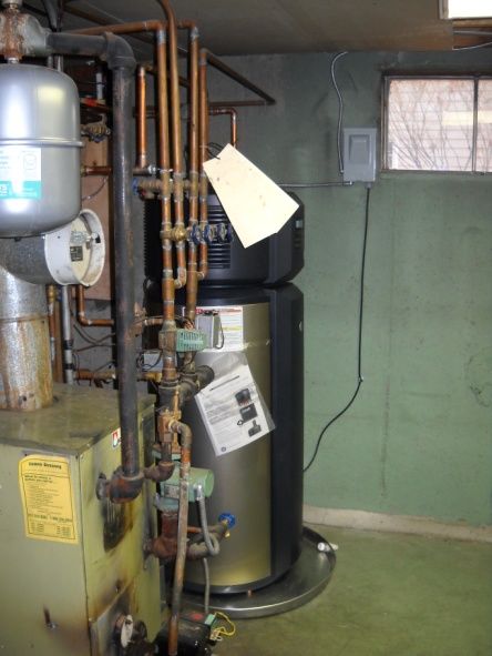
Measure Guideline: Heat Pump Water Heaters in New
                  and Existing Homes

                         Prepared for:
                       Building America
                Building Technologies Program
       Office of Energy Efficiency and Renewable Energy
                   U.S. Department of Energy

                           Prepared by:
      Carl Shapiro, Srikanth Puttagunta, and Douglas Owens
                 Steven Winter Associates, Inc.
                             of the
     Consortium for Advanced Residential Buildings (CARB)
                     50 Washington Street
                      Norwalk, CT 06854

          NREL Technical Monitor: Cheryn Engebrecht
       Prepared under Subcontract No. KNDJ-0-40342-02

                         February 2012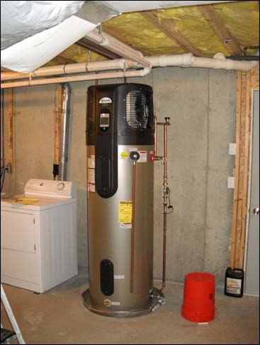
[This page left blank]

Contents
List of Figures ............................................................................................................................................ iv
List of Tables ............................................................................................................................................... v
Definitions ................................................................................................................................................... vi
Foreword .................................................................................................................................................... vii
Acknowledgements .................................................................................................................................. vii
Progression Summary ............................................................................................................................. viii
1 Introduction ........................................................................................................................................... 1
      1.1 Background ..........................................................................................................................1
      1.2 What Are Heat Pump Water Heaters? .................................................................................2
2     Cost and Performance ......................................................................................................................... 3
      2.1 Performance Metrics ...........................................................................................................3
      2.2 Energy and Cost Savings .....................................................................................................3
      2.3 What Affects Performance? .................................................................................................5
          2.3.1 Hot Water Usage ......................................................................................................5
          2.3.2 Ambient Temperature ..............................................................................................8
          2.3.3 Interaction with Space Conditioning Systems .........................................................9
          2.3.4 Inadequate Space .....................................................................................................9
      2.4 Dehumidification Potential ................................................................................................10
      2.5 Reliability and Safety.........................................................................................................10
3     HPWH Implementation Details .......................................................................................................... 11
      3.1 Selecting the Best Location for a HPWH ..........................................................................11
          3.1.1 Space Requirements ...............................................................................................11
          3.1.2 Conditioned or Unconditioned Space? ..................................................................12
      3.2 Proper Installation and Maintenance .................................................................................14
          3.2.1 Managing Condensate ............................................................................................14
          3.2.2 Heat traps ...............................................................................................................15
          3.2.3 Mixing Valves and Setpoint Temperature .............................................................16
          3.2.4 Filter Maintenance .................................................................................................16
          3.2.5 Typical Maintenance (for HPWH or ERWH) .......................................................17
References ................................................................................................................................................. 19
Appendix A: Measure Implementation Checklist................................................................................... 21
Appendix B: HPWH Installation Checklist (leave behind with unit)..................................................... 23

                                                                               iii
List of Figures
Figure 1. HPWH operation .......................................................................................................................... 2
Figure 2. Efficiency and electricity usage as a function of hot water demand ..................................... 6
Figure 3. Majority heat pump usage to meet demand ............................................................................. 7
Figure 4. Majority electric resistance usage to meet demand................................................................ 7
Figure 5. Efficiency of a 50-gal HPWH operating in heat pump mode .................................................. 8
Figure 6. Electricity usage for heat pump and lower element vs. inlet air temperature ...................... 9
Figure 7. HPWH installed with adequate clearances ............................................................................. 12
Figure 8. Improper HPWH with air discharge facing wall ..................................................................... 12
Figure 9. HPWH installed in boiler room ................................................................................................ 14
Figure 10. Condensate problems from improper installation .............................................................. 15
Figure 11. Proper HPWH installation ...................................................................................................... 15
Figure 12. HPWH without heat traps ....................................................................................................... 15
Figure 13. HPWH with heat traps ............................................................................................................. 15
Figure 14. Heat pump water heater with mixing valve .......................................................................... 16
Figure 15. Dirty filter: Finger rubbed against filter to show accumulation of dirt .............................. 17

Unless otherwise noted, all figures were created by the CARB team.

                                                                         iv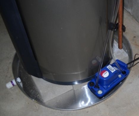
List of Tables
Table 1. 2005 RECS Data Sample of Households with ERWHs (Franco et al. 2010) ............................ 1
Table 2. Key Specifications of Some HPWHs Currently Available in the U.S. Market ......................... 1
Table 3. Comparison of Water Heaters by Fuel Type .............................................................................. 4
Table 4. HPWH vs. ERWH (U.S. Government EnergyGuide Labels) ...................................................... 4
Table 5. Expected Annual Energy Savings by House Size ..................................................................... 5
Table 6. Weight, Volume, Clearances, and Operating Temperatures for Various HPWH models .... 11
Table 7. Impact of Placing HPWH in Conditioned Space on Space Conditioning Usage ................. 13
Table 8. Time/Temperature Relationships in Scalds (Shriners Burn Institute) .................................. 16
Table 9. Water Heater Maintenance Schedule ....................................................................................... 17

Unless otherwise noted, all tables were created by the CARB team.

                                                                 v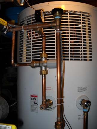
Definitions
CARB          Consortium for Advanced Residential Buildings

COP           Coefficient of Performance

DHW           Domestic Hot Water

EF            Energy Factor

ERWH          Electric Resistance Water Heater

GE            General Electric

IECC          International Energy Conservation Code

NREL          National Renewable Energy Laboratory

ROI           Return On Investment

SPB           Simple Payback Period

                                       vi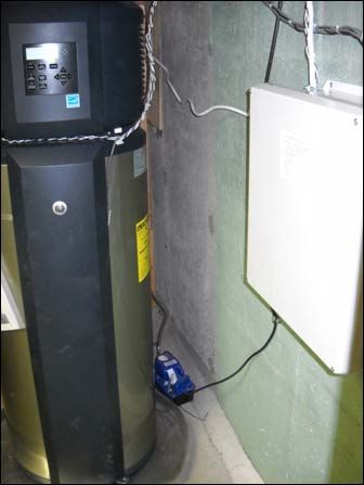
Foreword
Heat pump water heaters (HPWHs) promise to significantly reduce energy consumption for domestic hot
water (DHW) over standard electric resistance water heaters (ERWHs). While ERWHs perform with
energy factors (EFs) around 0.9, new HPWHs boast EFs upwards of 2.0. High energy factors in HPWHs
are achieved by combining a vapor compression system, which extracts heat from the surrounding air at
high efficiencies, with electric resistance element(s), which are better suited to meet large hot water
demands. Swapping ERWHs with HPWHs could result in roughly 50% reduction in water heating energy
consumption for 35.6% of all U.S. households.

This Building America Measure Guideline is intended for builders, contractors, homeowners, and policy-
makers. While HPWHs promise to significantly reduce energy use for DHW, proper installation,
selection, and maintenance of HPWHs is required to ensure high operating efficiency and reliability. This
document is intended to explore the issues surrounding HPWHs to ensure that homeowners and
contractors have the tools needed to appropriately and efficiently install HPWHs.

Section 1 of this guideline provides a brief description of HPWHs and their operation. Section 2
highlights the cost and energy savings of HPWHs as well as the variables that affect HPWH performance,
reliability, and efficiency. Section 3 gives guidelines for proper installation and maintenance of HPWHs,
selection criteria for locating HPWHs, and highlights of important differences between ERWH and
HPWH installations.

Throughout this document, CARB has included results from the evaluation of 14 heat pump water heaters
(including three recently released HPWH products) installed in existing homes in the northeast region of
the United States.

Acknowledgements
This guideline is the product of a collaborative effort. The authors acknowledge the funding and support
of the US Department of Energy’s Building America Program and our utility sponsors: National Grid,
NSTAR, and Cape Light Compact. Special thanks to Keith Miller and Andrew Wood of National Grid,
Richard Moran of NSTAR, and Margaret Song of Cape Light Compact.

                                                   vii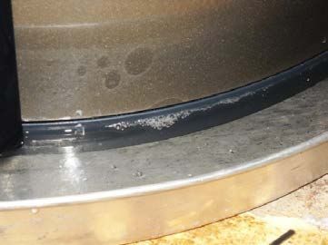
Progression Summary

            If Installing in Semi-/Un-                         If Installing in Conditioned
                Conditioned Space                                          Space

         Assess Available Location:                           Determine the interaction with
             • Sufficient room volume                         cooling and heating equipment:
             • Adequate ambient                                 Hot climates will have a net cooling
                 temperature                                    benefit, while cold climates will
             • Noise will not interfere                         have a net heating penalty (see
                 with living spaces                             Sections 2.3.3 and 3.1.2).
             • Drain is available for                           Generally, homes in climate zones
                 condensate collection                          1 and 2 have a net cooling benefit.

                                                              Select Available Location:
                              Fails

                                                                  • Sufficient room volume
                                                                  • Noise will not interfere with
                                                      Fails           living spaces
                                                                  • Drain is available for
                     Consider alternative high                        condensate collection
                  efficiency water heater options,
                      or evaluate the efficiency
                 impact of minimized heat pump
                             operation.

                            Passes                                         Install as directed

           If Installing in an Attached
                      Garage
                                                                  Passes

         Cold/Mixed
 Fails                                Hot Climate
          Climate

         Select Available Location:
 Fails       • Drain is available for
                 condensate collection

                                                     viii
1 Introduction
1.1 Background
Heat pump water heaters (HPWHs) promise to significantly reduce energy consumption for domestic hot
water (DHW) over standard electric resistance water heaters (ERWHs). While ERWHs perform with
energy factors (EFs) around 0.9, new HPWHs boast EFs upwards of 2.0. High energy factors in HPWHs
are achieved by combining a vapor compression system, which extracts heat from the surrounding air at
high efficiencies, with electric resistance element(s), which are able to help meet large hot water
demands. Water heating is the third largest contributor to residential energy consumption, after space
heating and space cooling (EERE 2011). Swapping ERWHs with HPWHs could result in roughly 50%
reduction in water heating energy consumption for 35.6% of all households nationally, as shown in Table
1.
Table 1. 2005 RECS Data Sample of Households with ERWHs (Franco et al. 2010)
Fraction of Households
Census Region with ERWH by Region
Northeast 17.1%
Midwest 26.7%
South 58.8%
West 21.5%
National 35.6%
While HPWHs are not new, products designed for the residential market have achieved minimal market
penetration in the past, primarily because past products were produced by smaller, niche-market
manufacturers, encountered reliability issues, and operated with limited market infrastructure. Although
HPWHs were first commercialized in the 1980s, they were typically add-ons to existing ERWHs, which
required specialized knowledge for installation and often required both an HVAC contractor and a
plumber to install the system. The development of drop-in HPWHs allowed for easy installation by a
single trade (Tomlinson 2002).
Recently, major manufacturers, such as General Electric (GE), Rheem, AO Smith, and Stiebel-Eltron,
have introduced “drop-in” HPWHs (Table 2). The development of these models has been fueled by the
large electric water heater replacement market and ENERGY STAR® certification of many HPWHs,
which often allows for state, federal, local, and utility rebates, tax credits, and other incentives.
Furthermore, the new federal water heater standard, which takes effect in 2015, mandates EFs around 2.0
for all new electric storage water heaters with capacities greater than 55 gallons (Federal Register 2010).
This regulation effectively mandates that water heaters be HPWHs in applications with large hot water
demands and the need for electric storage water heaters.
Table 2. Key Specifications of Some HPWHs Currently Available in the U.S. Market
First Hour
Capacity Energy Rating
Model (gal) Factor (GPH)
GE GeoSpring 50 2.35 63.0
AO Smith Voltex 60 / 80 2.33 68.0 / 84.0
Stiebel Eltron Accelera300 80 2.51 78.6
Rheem EcoSense 40 / 50 2.00 56.0 / 67.0
AirGenerate ATI 50 / 66 2.39 / 2.40 60.0 / 75.0
11.2 What Are Heat Pump Water Heaters?
In residential applications, the most common water heater appliances are electric resistance with storage
tank (ERWH), natural gas with storage tank, and tankless natural gas. HPWHs are designed as
replacements for standard ERWHs and are able to achieve higher energy factors by adding an additional
heating mechanism to existing ERWH designs. The primary heating mechanism is a heat pump
refrigeration cycle (like those in a refrigerator or air conditioner, but operating in reverse) that transfers
heat from the surrounding air to the water stored in the tank (Figure 1). Auxiliary electric resistance
elements are also included for reliability and quicker recovery. Unlike most previous models, most
current HPWHs are truly hybrids: They integrate a heat pump and electric resistance element(s) into a
single storage tank.
Figure 1. HPWH operation
The heat pumps can heat water in the storage tanks at high efficiencies, but the heat pumps have heating
capacities lower than those of traditional electric resistance elements. Typical 4.5-kW electric resistance
elements can reliably heat over 20 gallons of water per hour (GE 2011), whereas the heat pump has a
longer heating rate (GE claims 8 gallons per hour at 68°F air temperature). The efficiency of a HPWH
will vary considerably based on several operating parameters, such as inlet water temperature, tank
temperature, inlet air temperature, and temperature set point.
These units often have several modes of operation, such as hybrid mode, heat pump mode, and electric
resistance mode. The names of these modes differ by manufacturer, but most models include some
combination of the above. The hybrid mode uses both the electric resistance element(s) and the heat pump
to meet demand, but uses the heat pump whenever possible to maximize the efficiency of the unit. Heat
2pump mode includes only heat pump operation, which improves the efficiency of the unit, but reduces the
recovery capacity of the water heater. Electric resistance mode works like a traditional ERWH and can be
used when the ambient temperature of the space is inadequate or there is a problem with the heat pump.
2 Cost and Performance
Using HPWHs is a potentially cost-effective method of substantially reducing energy use for DHW when
compared to use of electric resistance water heaters. Section 2.2 explores the energy and cost savings of
HPWHs, while Section 2.3 explores the variables that affect the overall performance of HPWHs. Sections
2.4 and 2.5 discuss the dehumidification potential, reliability, and safety of HPWHs.
2.1 Performance Metrics
The efficiency of residential electric water heaters in the United States is measured and reported using the
energy factor (EF) value. The energy factor represents the efficiency of the electric element and tank
losses under a consistent, 24-hour test procedure. In this procedure, 64.3 gallons of water are drawn from
the tank in six equal draws spaced one hour apart. The temperature of the drawn water must be 135±5˚F
and the ambient temperature is 67.5˚F. The energy factor is simply the ratio of energy output to energy
input during the test procedure (Burch and Erickson 2004; Federal Register 1998).
Since the energy factor is defined under the specific test conditions outlined above, for a unit that operates
under real-world conditions or conditions different than the standard test, the coefficient of performance
(COP) is the term used here to describe the efficiency of the unit under the measured conditions. Like EF,
COP is the unit-less ratio of energy output to energy input during its operation.
When comparing energy use of water heaters using different fuels, EF or COP can be misleading because
energy use is only measured at the home and does not include energy lost to extraction, conversion, or
transmission of the energy. Therefore, water heaters using different fuels should be compared using a
different metric. While energy usage is usually measured in site energy, which is the energy used at the
home and is typically measured at a utility meter in units of kWh (electricity), therms (natural gas), or
gallons (fuel oil or propane), a better metric for measured energy usage is source energy, which is the sum
of energy used at the home and the energy lost to extraction, conversion, or transmission. Site energy
easily can be converted to source energy using a site-to-source ratio (Deru and Torcellini 2007) for the
given fuel.
When comparing water heaters that use different fuels, this guideline will use two metrics: cost to deliver
each unit of water heating energy ($/delivered mmBTU) and “source COP,” which is the efficiency of
converting source energy into water heating energy. These metrics include the efficiency of extraction,
conversion, and transmission.
2.2 Energy and Cost Savings
Traditional ERWHs are an inefficient and expensive form of water heating. As shown in Table 3 , electric
resistance water heating has the lowest source COP and the highest cost per mmBTU of delivered water
thermal energy. On the other hand, HPWHs have efficiencies and operating costs similar to natural gas
storage water heaters, making HPWHs an excellent choice for homeowners who currently use an electric
resistance, fuel oil, or propane water heater and do not have access to natural gas. Replacement of natural
gas water heaters with HPWHs is not recommended in heating dominated climates because HPWHs will
increase the load on the space heating system without a similar benefit to the space cooling system.
3Table 3. Comparison of Water Heaters by Fuel Type
Water Heater Storage Site-to-Source Source $/Delivered
Fuel Cost EF
Type Tank Ratio COP mmBTU
Electric
Tank 3.365 $0.1126/kWh 0.90 0.27 $36.67
Resistance
Heat Pump Tank 3.365 $0.1126/kWh 2.00 0.59 $16.50
Fuel Oil Tank 1.158 $2.8/gal 0.59 0.51 $34.22
Natural Gas Tank 1.092 $1.1633/therm 0.59 0.54 $19.72
Natural Gas Tankless 1.092 $1.1633/therm 0.82 0.75 $14.19
Condensing
Tankless 1.092 $2.03/gal 0.94 0.86 $12.38
Natural Gas
Propane Tank 1.151 $2.03/gal 0.59 0.51 $37.40
Marketed as replacements for electric resistance units, HPWHs promise to save considerable electric
energy and money over traditional ERWHs. According to the U.S. government EnergyGuides for a 50
gallon ERWH with an EF of 0.90 and a HPWH with an EF of 2.35, a HPWH could save 2,684 kWh per
year for an average family (Table 4). These water heaters are considerably more expensive to install than
traditional ERWHs, but electric savings will likely save more money over the course of the water heater’s
life. Table 4 shows the installation and annual operating costs, according to the National Renewable
Energy Laboratory’s (NREL) National Residential Efficiency Measures Database and the U.S.
government Energy Guide labels.
Table 4. HPWH vs. ERWH (U.S. Government EnergyGuide Labels)
Annual Electric Annual
Usage Installation Operating
Water Heater (kWh)† Cost* Costs†
HPWH (50 gal, EF = 2.35) 1,856 $2,100 $198
ERWH (50 gal, EF = 0.90) 4,879 $590 $520
* NREL National Residential Efficiency Measures Database
†
US Government Energy Guide Labels
Two methods of evaluating the cost effectiveness of energy efficiency measures are simple payback
(SPB) and return on investment (ROI). The SPB period is the ratio of incremental initial cost (dollars) to
annual energy savings (dollars/year).
The ROI is the ratio of net proceeds to the investment costs.
4Using the costs and savings in Table 4, the SPB period for HPWHs is 4.7, and the ROI is 113%.
Supporting Research
Field evaluations suggest that a 50-gallon HPWH has the potential to save a typical home 1,500 to 2,200
kWh per year, which represents a 45%-65% reduction in electricity usage for domestic hot water. These
results are not comparable to U.S. government estimates because they reflect varying household usage
patterns and, in some cases, the operation of the electric resistance element that reduces overall efficiency.
Utilizing a TRNSYS model, actual household usage data for a new 50-gallon HPWH were compared to a
typical 50-gallon ERWH with an EF of 0.92. The expected lifetimes of these units are 10 years, and 13
years, respectively. Using the Building America Standard Benchmark DHW Schedules for 1, 2, 3, 4 and 5
bedrooms (Hendron et al. 2010), expected annual energy savings for 1, 2, and 3+ bedroom houses are
between 1,750 and 2,200 kWh per year (Table 5).
Table 5. Expected Annual Energy Savings by House Size
Average Expected
Daily Hot Annual Annual
Number Water Energy Utility Payback
of Usage Savings Bill Return on Period
Bedrooms (Gallons) (kWh) Savings Investment (years)
1 35 1,750 $221 46% 6.6
2 45 2,000 $260 72% 5.8
3+ 55 2,200 $286 89% 5.3
2.3 What Affects Performance?
Although the cost and energy savings discussed in the sections above are quite compelling, real world
savings of each individual HPWH may be vastly different than those described above. Unlike
conventional ERWHs, the efficiency of HPWHs is hard to predict and strongly dependent on hot water
usage patterns (see Section 2.3.1) and ambient temperature (see Section 2.3.2). Furthermore, HPWH
operation may impact the space conditioning equipment, increasing heating loads and decreasing cooling
loads (see Section 2.3.3). Inadequate space and ambient temperature will also markedly reduce HPWH
efficiency (see Sections 2.3.4 and 2.3.4).
2.3.1 Hot Water Usage
The primary driver of the efficiency and energy usage of a HPWH is hot water demand (e.g. gallons used
per day). As with traditional ERWHs, standby losses reduce overall efficiency, particularly at lower hot
water demands. Unlike ERWHs, however, HPWHs experience a reduction in efficiency as electric
resistance heating is required to meet larger hot water demands.
There are two ways in which hot water consumption affects efficiency. Electricity consumption certainly
increases with overall water consumption (i.e. average gallons used per day). However, electric
consumption is even more dependent upon the intensity of hot water use. As the data below show, during
intense, high-volume hot water draws, a hybrid HPWH will often operate in electric resistance mode.
Electric resistance can provide more hot water faster, but it also consumes at least twice the electricity
when compared to heat pump mode.
Figure 3 shows one day’s worth of data where a HPWH uses the heat pump to satisfy all hot water needs.
Figure 4 shows the same HPWH relying exclusively on the electric resistance elements to meet demand
5for a day with the same total hot water demand (70 gallons). Each data point in these charts is the
totalized consumption over a 15 minute period. The first figure has a distribution of demand across the
day, while the second day has large, concentrated draws during the afternoon and evening.
Supporting Research
Overall efficiency peaks around 20-30 gallons per day and decreases with increased demand due to an
increase in hot water electric resistance element use. Overall electric usage strictly increases with
domestic hot water demand. Figure 2 shows the average COP and electricity used for one HPWH model
monitored during CARB’s HPWH evaluation. These curves are smoothed fits to daily data and are meant
to show the effect of hot water usage on efficiency and electricity usage.
2.5 20
Average Electricity Used (kWh/day)
Average COP
Average Electricity Used
2 16
Average COP
1.5 12
1 8
0.5 4
0 0
0 10 20 30 40 50 60 70 80 90 100
Daily Hot Water Usage (gallons/day)
Figure 2. Efficiency and electricity usage as a function of hot water demand
630.0 1200
25.0 1000
20.0 800
HW Used (Gallons)
Energy Used (Wh)
15.0 600
10.0 400
5.0 200
0.0 0
0:00 2:00 4:00 6:00 8:00 10:00 12:00 14:00 16:00 18:00 20:00 22:00 0:00
HW Use Upper Elelment Lower Element Heat Pump
Figure 3. Majority heat pump usage to meet demand
30.0 1200
25.0 1000
20.0 800
HW Used (Gallons)
Energy Used (Wh)
15.0 600
10.0 400
5.0 200
0.0 0
0:00 2:00 4:00 6:00 8:00 10:00 12:00 14:00 16:00 18:00 20:00 22:00 0:00
HW Use Upper Elelment Lower Element Heat Pump
Figure 4. Majority electric resistance usage to meet demand
72.3.2 Ambient Temperature
The efficiency of a HPWH increases substantially with increased ambient temperature (i.e. the air
temperature of the space where the HPWH is located). Heat pumps become much more efficient
when the heat source (in this case the ambient air) becomes warmer. Warmer air also reduces standby
losses.
Supporting Research
Figure 5 shows the effect of ambient temperature on the expected performance of a HPWH operating in
heat pump mode. Higher ambient temperatures result in considerably higher COPs. At increased water
use levels, an increase in ambient temperature from 50°F to 80°F results in an increase in COP of
approximately 0.5.
4 85
3.5 80
Coefficient of Performance
Ambient Temperature (°F)
3 75
2.5 70
2 65
1.5 60
Daily Values
1 50°F 55
60°F
0.5 70°F 50
80°F
0 45
0 10 20 30 40 50 60 70 80 90 100
DHW Demand (Gallons/Day)
Figure 5. Efficiency of a 50-gal HPWH operating in heat pump mode
The HPWHs will only operate in heat pump or hybrid mode if the ambient temperature of the air
entering the water heater is between ~45°F and ~110°F. When the temperature of the incoming air
drops below the minimum temperature, the HPWH will switch into electric resistance mode,
reducing the efficiency of the unit. In practice, the temperature of the space must be several degrees
above the minimum temperature due to the cooling effect of the heat pump operation, which drops
the temperature of the space. On the lower end of this temperature range, system efficiency can be
compromised due to:
• Increased electric resistance back-up heating
• Decreased hot water output
• Decreased hot water temperature rise.
8Supporting Research
As shown in Figure 6, heat pump operation dropped the ambient temperature by over 4°F, from 49°F to
near 45°F, which is the minimum allowable ambient temperature for this unit. Colder air temperatures
forced the electric resistance elements to turn on to meet hot water demand.
50.0 1400
49.0 1200
Inlet Air Temperature (F)
48.0 1000
Electricity Usage (Wh)
47.0 800
46.0 600
45.0 400
44.0 200
43.0 0
Inlet Temperature Heat Pump Energy Lower Element
Figure 6. Electricity usage for heat pump and lower element vs. inlet air temperature
2.3.3 Interaction with Space Conditioning Systems
As mentioned above, HPWHs transfer heat from the ambient air to water; this means HPWHs can have a
significant impact on the heating and cooling load of a building if the HPWH is installed in conditioned
space. HPWHs may reduce the ambient temperature 2F°-6°F when in operation (Stiebel- Eltron 2010),
though this is heavily dependent on HPWH run time and the space in which the HPWH is located. Often,
HPWHs are touted as providing free energy due to COPs greater than 1.0, but when located within the
building envelope, heat moved into the storage tank by a heat pump typically needs to be replaced by the
home’s heating system. HPWHs can extract between 4 and 11 MMBTU/year of energy from the
surrounding space. In hot climates, locating the HPWH in attached garages is an excellent way to
optimize water heating performance without concern for the cooling effect of the unit.
2.3.4 Inadequate Space
The HPWH must be able to extract sufficient energy from the surrounding air, and the energy available in
the air is primarily a function of the size of the space. Therefore, HPWHs must be installed in rooms with
adequate volume to ensure efficient operation (see manufacturer literature for space requirements).
Adequate clearances must be provided to allow for proper airflow and maintenance (see Section 3.1.1). If
a unit is installed in an area with insufficient space, the space can experience a dramatic reduction in
temperature during HPWH operation.
9Supporting Research
At one test site, the HPWH was installed in a location with inadequate space and showed a significant
reduction in efficiency. The HPWH was installed in a small, unconditioned basement mechanical
room with a door that was kept closed. The mechanical room’s area was approximately 440 ft3,
significantly less than the required 750 ft3 for the unit, contained a washer and dryer, and was used
for storage. The overall COP of the unit was 30% lower than the expected COP of a HPWH installed
with adequate space.
2.4 Dehumidification Potential
Because HPWHs remove heat from the ambient air using a heat pump refrigeration cycle, they also
remove moisture from the air. The water vapor in the air will condense as it passes across the HPWH’s
evaporator coils and, as a result, will provide dehumidification. This has the potential to reduce the need
for dehumidifiers in damp spaces, such as unconditioned basements. Although the dehumidification is not
predictable, because it relies on operation of the HPWH, the HPWH can reduce the energy consumed by
dehumidifiers in these spaces.
2.5 Reliability and Safety
Integrated (or “drop-in”) HPWHs are a relatively new technology that was first commercialized in the
early 2000s. Earlier models were “add-on” configurations that heated the water outside of the storage
tank. Unfortunately, the first commercialized, integrated HPWHs experienced problems with reliability
and safety.
Supporting Research
In 2004, evaluation of an early integrated HPWH, the WatterSaver HPWH, demonstrated effective COPs,
but some consistent drawbacks with the systems and their daily operation were identified, such as
excessively hot water temperature. Monitoring showed that water temperature near the top of the tank
often reached more than 150°F, partly because of excessive tank stratification – water temperatures near
the top could be 50°F higher than temperatures near the bottom. In fact, high-temperature switches in
many of the systems shut down the water heaters completely (high-temp safety switches are designed to
turn off water heaters when temperatures reach 170°F). Control boards were also replaced because of
problems with exposure to hot and humid conditions. Ultimately, because of the problems with installed
performance and a nonexistent service infrastructure, this product is no longer on the market.
Monitoring of the current 14 HPWHs, however, has shown no issues with safety to date. Only one
unit experienced a heat pump failure shortly after installation, but was quickly repaired by an
authorized service provider. Upon failing, the unit switched from hybrid mode to electric mode and,
as a result, the home did not experience a loss of hot water. Furthermore, all of the HPWHs under
evaluation have yet to display problems with excessive or inadequate hot water temperatures.
Although the higher complexity of HPWHs over standard ERWHs may lead to greater reliability issues,
so far modern HPWHs do not seem to be experiencing the same reliability issues that plagued earlier
models. An accelerated durability test of older HPWH models performed at Oak Ridge National
Laboratory found no long term reliability issues with these models (Baxter and Linkous 2004). These
early results suggest that modern HPWHs may last as long as traditional ERWHs under extended
operation.
103 HPWH Implementation Details
As noted in the introduction, hybrid heat pump water heaters are new to the mainstream market. Installing
contractors should be aware that installation of these units is not as straightforward as a standard electric
resistance water heater. Heat pumps require special attention to the air space (to ensure adequate air flow)
around the unit and require condensate collection and removal. Installers may not be familiar with these
units or heat pump models in general, and it can be difficult to install these units in existing homes.
3.1 Selecting the Best Location for a HPWH
Selecting an appropriate location for a standard ERWH is relatively straightforward. Any space large
enough for the water heater, piping, and servicing can be appropriate for an ERWH. However, HPWHs
require special consideration as they require more space (see Section 2.3.4) and weigh more than
traditional ERWHs. The added weight of these units, due to the heat pump components, may mean that
two or more people are required to move and install the unit. Furthermore, the best location must be
chosen with respect to the interaction with the space conditioning equipment, the ambient temperature of
the space, and noise (see Section 3.1.2). For reference, Table 6 lists the weight, volume, clearance, and
operating temperature requirements for several current HPWH models (this is presented as an example;
for accurate information, refer to up-to-date literature for specific HPWHs).
Table 6. Weight, Volume, Clearances, and Operating Temperatures for Various HPWH models
Minimum Minimum Clearances HP Inlet Air
Dry Wet Room Operating
Weight Weight Volume Air Air Temperature
Model (lbs) (lbs) (ft3) Inlet Outlet Front Rear Top (°F)
GE 190 602 700 7" 7" 5.5" 5.5" 14" 45-120
Rheem 197 576/680 1,000 N/A N/A N/A 2" 8" 40-120
AO 332*/ 827/
750 3' 5' 2' 6" None 45-109
Smith 410* 1,069
Stiebel-
287 952 500 16" 15.75" 8" 8" 16" 42-108
Eltron
* shipping weight
3.1.1 Space Requirements
The HPWHs require more space than traditional HPWH Space Requirements Checklist
ERWHs because of their additional height, Does the room meet the volume requirements of the
weight, required air volume, and clearance unit (> 750 ft3)?
requirements; HPWHs are generally taller and Are the ceilings high enough to accommodate the
heavier than traditional ERWHs. Measures to extra height of the HPWH?
manage condensate, such as placing the unit on
Is there adequate space to allow maintenance of the
blocks (see Section 3.2.1), may further increase heat pump components?
the height requirements of HPWHs. The
additional weight of the unit, particularly larger Can the HPWH be placed in the room such that
there is sufficient clearance for airflow around the
capacity models, may require reinforcement of unit?
the floor to ensure structural soundness.
Is there enough clearance for removal and cleaning
of the air filter?
Because HPWHs extract energy from their
surrounding environment (see Section 1.2), Is the floor able to support the additional weight of
enough air volume and adequate clearances must the HPWH?
be provided to allow for proper operation of the
unit. Improperly placed HPWHs are significantly
11less efficient than properly installed units (see Section 2.3.4). Generally, HPWHs must be installed in a
room with a volume of at least 750 ft3, which corresponds to a 10 ft by 10 ft room with 7’6” ceilings.
Furthermore, HPWHs require larger clearances for proper operation. Air entry and discharge must be free
of obstructions to provide proper air circulation and ensure a continuous supply of fresh air. Figure 7
shows a properly installed HPWH with adequate clearances at the air entry and discharge, while Figure 8
shows a poorly installed unit with the air discharge directed towards a wall. Added clearances are also
required for removal and cleaning of the air filter and for servicing of the unit. Piping installation must be
carefully considered to prevent the pipes from blocking the air filter or maintenance panels.
Figure 7. HPWH installed with adequate Figure 8. Improper HPWH with air discharge
clearances facing wall
3.1.2 Conditioned or Unconditioned Space?
When selecting an appropriate location for a HPWH, the interaction with the heating and cooling system
must be closely considered. As mentioned in Section 2.3.3, HPWHs extract heat from the surrounding air
and therefore increase heating loads and decrease cooling loads when installed in conditioned spaces. An
analysis of the total impact on heating and cooling source energy usage (Table 7) reveals that for the vast
majority of the United States, there is a net potential heating penalty on source energy usage for space
conditioning. Cities in climate zone 2 may have a net potential cooling benefit. If the decision is made to
relocate an interior water heater to a semi-conditioned space (i.e. garage or basement), consideration
needs to be given regarding the impact on distribution system performance and hot water waiting times.
12Table 7. Impact of Placing HPWH in Conditioned Space on Space Conditioning Usage
Climate
City Zone HDD65 CDD65 Potential Impact
Atlanta, GA 3A 2,694 1,841 Heating Penalty
Baltimore, MD 4A 4,567 1,228 Heating Penalty
Boston, MA 5A 5,621 750 Heating Penalty
Chicago, IL 5A 6,311 842 Heating Penalty
Denver, CO 5B 5,942 777 Heating Penalty
Houston, TX 2A 1,414 3,001 Cooling Benefit
Orlando, FL 2A 544 3,379 Cooling Benefit
Phoenix, AZ 2B 941 4,557 Cooling Benefit
San Francisco, CA 3C 2,708 142 Heating Penalty
Seattle, WA 4C 4,729 177 Heating Penalty
Conditioned Space
In climates with a net heating penalty, it is not advisable to place HPWHs in conditioned space without
further exploring the potential impact. In locations with potential cooling benefit, HPWHs may be placed
in conditioned space, although special consideration must be used when deciding the best location for the
HPWH. Although these units have a potential to reduce overall space conditioning loads, the cooling
from these units may lead to over-cooling of the space because the operation of the unit is not controlled
by a thermostat. Follow these guidelines when choosing a proper location for the HPWH:
• Never place the unit close to a thermostat, as this may result in improper heating or cooling
of the home.
• Never place the unit near the kitchen. Oils from cooking can ruin the unit.
• Place the unit in a location that is not sensitive to
colder temperatures.
• Make sure to meet the manufacturer’s space
requirements (e.g. Section 3.1.1). Do not place the
unit in a closet unless the closet door has a
louvered door. Even with a louvered door, locating
the HPWH in a closet will likely reduce overall
performance of the unit. When installing a HPWH in a room
with a furnace, ensure that the unit
• Noise may be an issue because the HPWH uses a does not interfere with operation of
compressor and fan to move air through the unit. the furnace. Air flows inside the room
will change as a result of HPWH
Do not place the unit near bedrooms or other installation.
noise-sensitive locations.
Unconditioned Space
In most U.S. climates, HPWHs can be placed in unconditioned or semi-conditioned spaces. Semi-
conditioned spaces are spaces that are inside the thermal boundary, but not directly heated or cooled. The
most common semi-/unconditioned locations are garages and basements. Crawlspaces are generally too
short for HPWHs, and HPWHs are typically not recommended to be placed in attics (because of potential
for water leaks, weight of unit, ambient temperature that fluctuates outside the heat pump’s operating
range, etc.).
13The primary consideration for unconditioned spaces is the size of the room (see Section 3.1.1) and the
ambient temperature of the space. The minimum temperature of the space should not be below 50°F.
Operation of the HPWH will result in a significant drop in ambient temperature, and such a drop may
result in an air temperature below the minimum recommended operating temperature in heat pump mode
(see Section 2.3.2). HPWHs with electric resistance modes may be placed in colder basements, but the
HPWH will not operate at its rated efficiency during colder months. In more temperate climates, the
attached garage can be a suitable location, as long as plumbing lines are not too long and can be properly
insulated. In colder climates, however, the basement will likely have the highest temperature of all
unconditioned spaces.
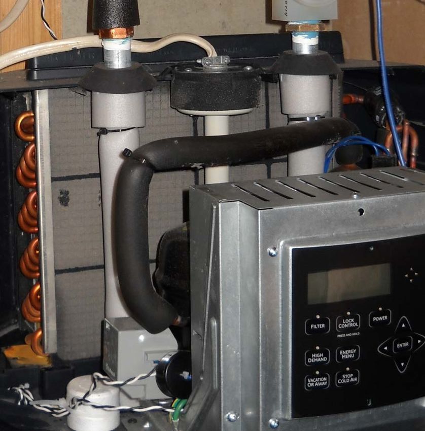
Interesting Fact
At one site in CARB’s evaluation of 14 HPWHs, the unit was
placed in an unfinished basement in the mechanical room next to
the boiler. The waste heat from the boiler increased the ambient
temperature of the room in the winter, meaning that the room
was 70°F or warmer throughout winter. The waste heat improves
the efficiency of the HPWH and minimizes the impact of the
HPWH on the space heating loads of the house.
Figure 9. HPWH installed in boiler room
3.2 Proper Installation and Maintenance
Good installers of HPWHs pay close attention to HPWH Installation Checklist
condensate management (Section 3.2.1), heat traps Place the unit on blocks
(Section 3.2.2), and mixing valves (if applicable, Install a drain pan
Section 1.1.1). Proper maintenance includes inspection
of the condensate lines and regular cleaning of the air Install a condensate pump, if applicable
filter. Installations should always comply with local Install heat traps to prevent thermosiphoning
and state codes.
Install a mixing valve, if applicable
3.2.1 Managing Condensate
As warm, moist air travels over the evaporator coils of a HPWH, some moisture in the air will condense,
and the resulting condensate is removed from the unit through a condensate drain line. This condensate
must be effectively removed to prevent damage to the unit. While manufacturer’s condensate
requirements vary slightly, in the simplest configuration a hose is connected to the condensate line and
properly pitched toward a drain in the floor. If a suitable drain is not available, a condensate pump must
be installed to ensure that condensate is properly removed. Based on contractor feedback, a 240V
condensate pump is recommended for this application to avoid potential call backs related to tripped
ground-fault circuit interrupter (GFI) outlets used to power 120V condensate pumps.
14To protect the unit from a condensate line failure or other condensate issue, HPWHs should be installed
on blocks with a drain pan. These precautions prevent the unit from sitting in water and ensure that the
condensing water is properly transferred to a drain.
Drain pans are used to capture overflow due to condensate pump failure, piping failure, and condensate
line obstructions. Because HPWHs are relatively new to the mainstream market, the installers may not be
aware of the need for drain pans. Given the low cost, all HPWHs should have a drain pan installed.
Concrete blocks are often used to raise the bottom of the unit above the lip of the drain pan which
prevents the bottom of the unit from resting in water (and possibly corroding should a leak occur). Figure
10 shows a HPWH that does not properly remove condensate away from the unit into the drain. The unit
ended up sitting in water due to a kinked condensate line. Figure 11 shows a proper HPWH installation,
where the unit is set on blocks in a drain pan and a condensate pump is used.
Figure 10. Condensate problems from Figure 11. Proper HPWH installation
improper installation
If the condensate line becomes clogged or kinked, the drain hose must be removed and cleared of any
debris. The owner should periodically inspect and clear any debris from the condensate line to prevent
condensate overflow.
3.2.2 Heat traps
Heat traps should be installed on all hot water systems to prevent thermosiphoning, which is the transfer
of heat from the storage tank down the cold or hot water lines. Thermosiphoning reduces the efficiency of
the unit by increasing the standby losses to the environment. Figure 12 shows a HPWH installed without
heat traps, while Figure 13 shows a properly installed HPWH with heat traps.
Figure 12. HPWH without heat traps Figure 13. HPWH with heat traps
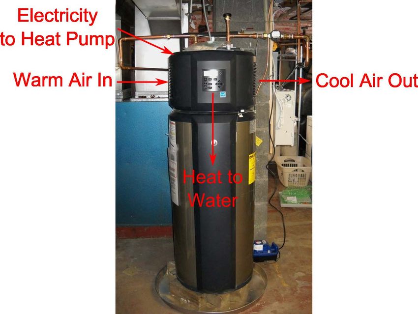
153.2.3 Mixing Valves and Setpoint Temperature
With any water heater that generates relatively high water temperatures a mixing valve should be installed
to minimize the risk of burns or scalding (see Table 8). If a HPWH generates temperatures above 125F°-
130°F (or if the temperature is likely to be set above this), a mixing valve should be installed (Figure 14).
Table 8. Time/Temperature Relationships in Scalds (Shriners Burn Institute)
Temperature Time to Produce a Serious Burn
120 More than 5 minutes
125 1.5 – 2 minutes
130 About 30 seconds
135 About 10 seconds
140 Less than 5 seconds
145 Less than 3 seconds
150 About 1.5 seconds
155 About 1 second
Mixing Valves
The hot water outlet temperature may
change over the course of the year,
increasing during the summer as the mains
temperature increases.
HPWH Piping Issues
The inlet and outlet pipes of most ERWHs
enter the top of the unit. Due to the inclusion
of the heat pump at the top of the unit, some
HPWHs have different locations and
orientations of the water lines. In Figure 14,
the water lines enter the unit at the side and
are placed horizontally. This orientation will
likely require additional plumbing.
Furthermore, the air filter in some units is
placed near the water piping. As a result, the
installer must pay close attention to the
piping installation to avoid obstructing the
air filter.
Figure 14. Heat pump water heater with mixing valve
Just as a high water temperature could result in scalding, a low temperature could result in the growth of
the bacterium Legionella, which causes lung infections. This bacterium thrives in warm water, but
temperatures over 119°F will minimize Legionella growth. Temperatures above 122°F will kill 90% of
the bacteria in 80-124 minutes, and temperatures above 140°F will kill 90% of the bacteria in 2 minutes
(WHO 2007). Temperatures around 120°F (but not less than 119°F) are the recommended temperature set
point to minimize scald potential and reduce standby losses while maintaining water quality. If the
vacation mode of a water heater is used (or temperature setpoint lowered), ensure that the unit is given
adequate time to recover to a temperature higher than 122°F for several hours upon return from vacation
before using the hot water.
3.2.4 Filter Maintenance
If a HPWH has an air filter, the filter must be regularly cleaned to ensure that the unit runs at peak
efficiency. In Figure 15, a HPWH with a dirty air filter is shown. On some units, the air filter is removed
from the top of the unit, and therefore extra clearance must be provided to ensure that the unit’s filter can
be properly cleaned.
16Figure 15. Dirty filter: finger rubbed against filter to show accumulation of dirt
3.2.5 Typical Maintenance (for HPWH or ERWH)
In addition to cleaning the air filter, both HPWHs and ERWHs require regular maintenance to ensure
proper operation and extend the life of the unit. Table 9 lists the required maintenance items for water
heaters and the recommended timing.
Table 9. Water Heater Maintenance Schedule
Maintenance Item When? Why?
Check temperature pressure relief
Yearly Ensure proper operation
valve
Prevent hard water deposits from
Discharge water from tank Monthly
accumulating
Inspection by qualified service
Yearly Ensure proper operation
provider
17Check Temperature Pressure Relief Valve
Lift and release the lever handle on the temperature pressure relief valve (check manual for
location).
Ensure lever moves freely.
Allow several gallons to flow through the discharge line to an open drain.
Discharge Water from Tank
Suspended solids in tap water may settle at the bottom of a water heater’s tank. To ensure that these solids
do not collect at the bottom of the tank, a few quarts of water should be drained from the drain valve of
the tank every month. See the section below for instructions for draining the tank.
Draining the Tank
Note: Drainage hose should be rated for at least 180°F. Otherwise, turn off power to water heater and
open hot water faucet until the water runs cold.
Shut off power to the water heater.
Turn off cold water supply.
Helpful Tip
Open a hot water faucet to allow air to enter the tank. Even new electrical
appliances may make
Attach a hose to the drain valve on the water heater and direct hissing or singing sounds
the stream of water to a drain. during operation.
However, if these noises
Open the relief valve. increase excessively, the
Drain water heater. electric resistance elements
may need cleaning.
Close relief valve. Contact a qualified
installer or plumbing
Disconnect hose from valve. contractor to inspect the
unit.
Turn on cold water supply.
Keep hot water faucet open until water runs through the faucet.
Close hot water faucet.
Turn on power to the water heater.
Inspection by Qualified Service Provider
Periodically contact a qualified electric appliance repair service provider to inspect the operating controls,
heating elements, anode rod, and wiring.
18References
Amarnath, K. R.; Trueblood, C. (2010). “Heat Pump Water Heaters: Laboratory and Field
Evaluation of New Residential Products.” Proc. Summer Study on Energy Efficiency in
Buildings (1); American Council for an Energy-Efficient Economy; pp. 12-23.
AIL Research, Inc. (2001). “Northeast Utilities Heat Pump Water Heater Field Test: 30 Crispaire
Installations.”
AIL Research, Inc. (2002). Nyle Heat Pump Water Heat Evaluation
A.O. Smith (2010). “VoltexTM Hybrid Electric Heat Pump Water Heater Installation Instructions
and Use & Care Guide.”
Baxter, V.; Linkous, R. (2004). “Heat Pump Water Heater Durability Testing – Phase II.” Oak
Ridge, TN: Oak Ridge National Laboratory; ORNL/TM-2004/111.
Burch, J.; Erickson, P. (2004). “Using Data to Derive Simulation-Model Inputs for Storage-Tank
Water Heaters.” Portland, OR: Proceedings of the Solar 2004 Conference. pp. 393-398
[CARB 2010] Consortium for Residential Buildings (2010). “Retrofitting America: A 1970s
Home Energy Efficiency Analysis.”
http://carb-swa.com/articles/homepage/RetrofittingAmerica_1970sHomeAnalysis.pdf
Deru, M; Torcellini, P (2007). Source Energy and Emission Factors for Energy Use in Buildings.
Golden, CO: National Renewable Energy Laboratory.
[EERE 2011] U.S. Department of Energy, Energy Efficiency and Renewable Energy; “Table
2.1.5 2008 Residential Energy End-Use Splits, by Fuel Type (Quadrillian Btu).” Building Energy
Data Book; http://buildingsdatabook.eren.doe.gov/TableView.aspx?table=2.1.5; Date Access:
July 17, 2011.
Federal Register, (2010). Vol. 75, No. 73 p. 20114 10CFR 430.
Federal Register, (1998). Vol. 63, No. 90 p. 25995 10CFR 430.
Franco, V.; Lekov, A.; Meyers, S.; Letschert, V. (2010). “Heat Pump Water Heaters and
America Homes: A Good Fit?” Proc. Summer Study on Energy Efficiency in Buildings (9);
American Council for an Energy-Efficient Economy; pp. 68-79.
[GE 2010] General Electric (2010). “Owner’s Manual & Installation Instructions.” 49-50254 10-
09 JR
[GE 2011] General Electric (2011). “Water Heater FAQs: How long should my GeoSpring water
heater run in order to reheat the water in the water heater?” http://www.geappliances.com/heat-
pump-hot-water-heater/water-heater-faq.htm#recoveryTime Accessed 25 April 2011
Glanville, P., and D. Kosar, 2011. Building America Industrialized Housing Partnership II-
Subtask 2.2.3: Efficient Hot Water and Distribution Systems Research. Gas Technology Institute
19project number 20970. and also, Pacific Gas & Electric Company, 2010. Laboratory Evaluation
and Field Testing of Residential Heat Pump Water Heaters. PG&E Applied Technology Services
Test Report #:491-10.04.
Hendron, B.; Burch, J.; Barker, G. (2010). “Tool for Generating Realistic Residential Hot Water
Event Schedules.” New York, NY: SimBuild 2010.
[IECC 2009] International Code Council, Inc. (2009). 2009 International Energy Conservation
Code. Country Club Hills, IL.
[ORNL 2002] Oak Ridge National Laboratory (2002). “Field Tests of a ‘Drop-In’ Residential
Heat Pump Water Heater.”
[PGEC 2009] Pacific Gas and Electric Company (2009). “Energy Performance Analysis for Heat
Pump Water Heaters.” Application Assessment Report #0916.
Rheem (2009). “Use & Case Manual: Electric Residential Heat Pump Water Heaters.”
Stiebel-Eltron (2010). “Operating and Installation Manual: DHW Heat Pump Water Heater
Accelera® 300.”
[SWS] National Renewable Energy Laboratory (2011). “Workforce Guidelines for Home Energy
Upgrades.”
Tomlinson, J. J. (2002). “All Pumped Up: New heat pump water heaters consume half the energy
of conventional electric-resistance ones.” Home Energy; November/December 2002; pp. 30-35.
Tomlinson, J. J.; Rice, C.K.; Baskin, E. (2005). “Integrated Heat Pumps for Combined Space
Conditioning and Water Heating.” 8th IEA Heat Pump Conference Paper.
[WHO 2007] World Health Organization (2007). “Legionella and the Prevention of Legionellosis.”
Yates, D. (2010). “Keep selling heat pump water heaters after tax credit expires.” Contractor
Mag; http://contractormag.com/columns/yates/selling-pump-water-heateers-0610; June 9, 2010
Accessed 25 April 2011.
Zogg, R. (2002). “Residential Heat Pump Water Heater Technology and Markets Seminar.”
December 4-5, 2002; Portland, OR.
20You can also read