Operating Room Information System Pre-Installation Manual - 1004-400-059 REV L - Infrastructure BC
←
→
Page content transcription
If your browser does not render page correctly, please read the page content below
Operating Room Information System

                            Pre-Installation Manual

2015/03
        				1004-400-059 REV L				www.stryker.com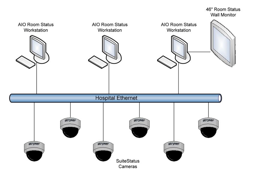
Operating Room
                               Information System
                                     Pre-Installation Manual

This manual contains confidential information that shall not be disclosed or duplicated for any reason
other than to use and maintain a STRYKER OPERATING ROOM INFORMATION SYSTEM. This
restriction does not limit the right to use information contained in this manual if it is obtained from
another source without restriction. The information subject to this restriction is contained in all pages
of this manual.

© 2015/03 Stryker Communications. All Rights Reserved. Information in this document is subject to
change without notice.
Stryker and Stryker logo are registered trademarks of Stryker. Endosuite® OR and iSuite® are registered
trademarks of Stryker.
All Rights Reserved
Operating Room Information System Pre-Installation Manual
1004-400-059 REV L
S
Contents
1. Scope..................................................................................................................................................................... 4
2. Warnings and Cautions.......................................................................................................................................... 5
2.1 Warnings............................................................................................................................. 5
3. Product Symbol Definition.................................................................................................................................... 6
3.1 EMC Precautions................................................................................................................... 7
4. Party Responsibilities............................................................................................................................................ 8
4.1 Hospital Responsibilities ...................................................................................................... 8
4.2 Contractor Responsibilities .................................................................................................. 8
4.3 Stryker Responsibilities ....................................................................................................... 9
5. iSuite Operating Room ....................................................................................................................................... 10
5.1 Documentation Station (Stryker Provided).......................................................................... 10
5.1.1 Receiving and Assembling the Documentation Station.................................................10
5.1.2 Additional Documentation Station Notes....................................................................11
5.1.3 Installing the Documentation Station.........................................................................12
5.2 Documentation Station (Hospital Provided)......................................................................... 16
5.3 Documentation Station Equipment Requirements ............................................................... 16
5.4 iSuite Equipment Integration Notes.................................................................................... 19
5.4.1 Wall Mounted 46" or 55" LCD Monitor or 42" TouchPanel...............................................19
5.4.2 Wall/Ceiling Mounted Room Status Camera (WRC, CRC) LA ...........................................19
5.4.3 Wall Plates................................................................................................................20
5.4.4 Observation Room Touch Panel, Microphone and Speaker (OBS) LA ..............................20
5.4.5 Cable Run to Video Network Hub (HRN).......................................................................20
5.4.6 Equipment Boom Cable Kit (Brand) (EQB)....................................................................21
5.4.7 Anesthesia Boom Cable Kit (Brand) (ANB)....................................................................21
5.4.8 Navigation Arm (NAM)................................................................................................21
5.4.9 Stryker Single Flat Panel Arm Cable Kit........................................................................22
5.4.10 Stryker Dual Flat Panel Arm Cable................................................................................22
5.4.11 Single Flat Panel Arm Cable Kit (Non-Stryker Flat Panel Arm) (NAM)...............................22
5.4.12 Dual Flat Panel Arm Cable Kit (Non-Stryker Flat Panel Arm)..........................................22
6. Infinity Based Conference System (IBC) Rooms LA
.............................................................................................. 23
6.1 SPI3 Customer Supplied Casework (SCW)............................................................................. 23
1S
6.2 IBC Unit with Tower (ICW1) LA
............................................................................................ 23
6.3 IBC Unit with Stryker Credenza (ICW2) LA
........................................................................... 23
6.4 IBC with Customer Supplied Casework (ICW3) LA
................................................................. 24
6.5 Casework Equipment.......................................................................................................... 24
6.5.1 SwitchPoint Infinity 2 (A2) LA ....................................................................................24
6.5.2 SPI2 Touch Panel, 19" (B2)..........................................................................................24
6.5.3 Wireless Microphone Receiver (M)...............................................................................24
6.5.4 SD CODEC (L1).............................................................................................................25
6.6 IBC Podium with Touch Panel LA
........................................................................................ 25
7. Level Systems Room............................................................................................................................................. 26
7.1 Customer Supplied Casework (CSC)....................................................................................... 26
7.2 Casework Equipment ......................................................................................................... 26
7.2.1 Level One System (S1) LA
...........................................................................................26
7.2.2 Level Two System (S2) LA ...........................................................................................26
7.2.3 Level System Touch Panel (T)......................................................................................27
7.3 Remote Level System Touch Panel (LTP) ............................................................................... 27
8. Equipment Integration Notes............................................................................................................................... 28
8.1 Wall Mounted 46" or 55" LCD Monitor, or 42" Touch Panel LA
................................................. 28
8.1.1 SPI3 Cable Specifications............................................................................................28
8.1.2 SPI3 42” Touch Panel Cable Specifications....................................................................28
8.1.3 IBC Cable Specifications LA ........................................................................................28
8.1.4 Level System Cable Specifications...............................................................................29
8.2 Motorized Projection Screen (MPS)....................................................................................... 29
8.3 Motorized Projection Screen Wall Switch (SWS)..................................................................... 29
8.4 Ceiling Mounted Projector.................................................................................................... 29
8.4.1 SPI3 Cable Specifications............................................................................................29
8.4.2 IBC Cable Specifications..............................................................................................30
8.4.3 Level System Cable Specifications...............................................................................30
8.5 Bracket Mounted Wall /Ceiling Speaker................................................................................. 30
8.6 Flush Mounted Rectangular Wall/Ceiling Speaker.................................................................. 31
8.7 Flush Mounted Circular Ceiling Speaker................................................................................. 31
8.8 Wall/Ceiling Mounted Pan/Tilt/Zoom Camera LA
................................................................... 31
2S
8.9 Wall/Ceiling Mounted HD Pan/Tilt/Zoom Camera LA
.............................................................. 32
8.10 Echo Canceling Microphone with Internal Speaker LA
.......................................................... 32
8.11 Ceiling Mounted Microphone.............................................................................................. 33
8.12 Lutron Controller (LTC)........................................................................................................ 33
8.13 Lutron Lighting Control Integration Series........................................................................... 33
8.14 Outside the OR Touch Panel, Keyboard, Mouse for SPI3......................................................... 33
9. ConnectSuite ...................................................................................................................................................... 35
9.1 SuiteStream...................................................................................................................... 35
9.2 SuiteLink/SuiteView........................................................................................................... 35
9.3 Offsite Package.................................................................................................................. 35
10. Status Systems LA
............................................................................................................................................ 36
10.1 Operating Room Status Systems.......................................................................................... 36
10.1.1 Partial Floor and Elevation Drawings...........................................................................36
10.1.2 Site Preparation Requirements...................................................................................37
10.2 SuiteStatus Systems........................................................................................................... 38
10.3 Site Preparation Requirements........................................................................................... 39
10.3.1 SuiteStatus System....................................................................................................39
10.3.2 Power.......................................................................................................................39
10.3.3 Mounts......................................................................................................................39
10.3.4 External Display.........................................................................................................39
Appendix A: PRI Provisioning Instructions and Form................................................................................................ 41
A.1 Setting Up a PRI Line.......................................................................................................... 42
A.2 PRI Setup Responsibility Matrix.......................................................................................... 42
Appendix B: ORIS Network Connectivity................................................................................................................... 45
B.1 Network Connectivity Information ..................................................................................... 45
B.1.1 Ports and Bandwidth.................................................................................................45
B.1.2 Gateway/Session Border Controller (V2IU)...................................................................45
B.1.3 Bridging Services.......................................................................................................45
B.2 Network Connectivity Questionnaire (Response Required)....................................... 46
Appendix C: Remote Device Management Network Security SORN.......................................................................... 47
Appendix D: OSHPD Pre-Approved Mounting Solution............................................................................................. 49
Contact Information................................................................................................................................................. 51
3S
1. Scope
This document describes the rough-in requirements and specifications for Stryker Operating Room
Information System (ORIS) equipment. It covers pre-installation requirements for all electrical and
information systems services needed. It does not describe in detail the installation of this equipment
which is accomplished by Stryker Communications' technicians.
Note Please refer to the Boom and Lights Pre-Installation Manuals for mechanical and
structural requirements for Stryker equipment booms, surgical lights, flat panel
arms, and navigation arms.
Note Junction boxes are called out in this manual. The term dual gang junction box
with single gang mud ring refers to an actual dual gang junction box with an
adaptor that is designed for attachment of a single gang wall plate. This provides
more internal room for cabling and wire termination. The exact type used de-
pends on local building codes and electrical standards.
4S
2. Warnings and Cautions
Please read this manual and follow its instructions carefully. The words WARNING, CAUTION, and
Note carry special meanings and should be carefully reviewed.
WARNING The personal safety of the patient or user may be involved. Disregarding
this information could result in injury to the patient.
Caution Special service procedures or precautions must be followed to avoid dam-
aging the instrument.
Note Special information to make maintenance easier or important information more
clear.
2.1 Warnings
To avoid potential serious injury to the user and the patient, the user must:
1. Read this manual thoroughly, and be familiar with its contents prior to using this equipment.
2. Be qualified physician/technician or medical personnel, having complete knowledge of the use
of this equipment.
3. Test this equipment prior to a surgical procedure. This product was fully tested at the factory
before shipment.
4. DO NOT remove covers on the product, to avoid an electric shock.
5. DO NOT perform internal repairs or adjustments unless specifically instructed to do so in this
manual.
6. The electrical installation of relevant operating room equipment must comply with the appli-
cable IEC, CEC, and NEC requirements, and any other applicable international requirements
where this product is sold. In the case where the information in this manual conflicts with local
building/electrical regulations, local regulations will take precedence.
5S
3. Product Symbol Definition
The following symbols may be found on the Stryker SwitchPoint Infinity® 3 equipment:
An exclamation mark within a triangle is intended to alert the user to the presence
of important operating and maintenance (service) instructions in the literature ac-
companying the product.
A lightning bolt within a triangle indicates the presence of hazardous voltage. Refer
all service to authorized personnel.
Denotes temperature limits.
Denotes humidity limits.
Denotes pressure limits.
Denotes usage tips and useful information.
Denotes compliance to European Community Directive 93/42/EEC.
Denotes compliance to CSA Standard C22.2, 60601-1 - M90, AS 3200, IEC 60601-1,
UL 60601-1, EN 60601-1
Denotes the date the equipment was manufactured.
Denotes the manufacturer of the device.
Denotes product/part number.
Denotes product/serial number.
Denotes lot or batch number.
Denotes European Representative.
For U.S. audience only - Caution: Federal Law (USA) restricts this device to sale by
or on the order of a physician.
Denotes quantity.
6S
Denotes Class 1
Class 1 Equipment: equipment in which the protection against electric shock does
not rely on Basic Insulation only, but includes an additional safety precaution in
such a way that means are provided for the connection of Accessible Conductive
Parts to Protective (ground) Conductor in the fixed wiring of the installation in such
a way that Accessible Conductive Parts cannot become Live in the event of a failure
of the Basic Insulation.
In accordance with European Community Directive 2002/96/EC on Waste Electri-
cal and Electronic Equipment, this symbol indicates that the product must not be
disposed of as unsorted municipal waste but should be collected separately.
Note: The device does not contain any hazardous materials.
Legal regulations may include specifications regarding the disposal of this prod-
uct. We request that you contact Stryker when you plan to withdraw this device
from service for discard.
Denotes the device contains more than .002% cadmium.
Denotes the device contains more than .0005% mercury.
Denotes the device contains more than .004% lead.
Limited Availability - Equipment may not be available in all regions.
LA
Not Stryker Provided - Doc Stations must be provided by the customer outside the
NSP
U.S.
3.1 EMC Precautions
This device is considered medical electrical equipment and requires special precautions regarding
EMC and needs to be installed and put into service according to the information provided.
Portable and mobile RF communications equipment can affect this device's performance and must be
used in accordance with the following information.
WARNING The use of accessories, transducers, or cables other than those specified,
with the exception of those sold by Stryker, may result in increased emis-
sions or decreased immunity of the equipment or system.
WARNING The equipment should not be used adjacent to or stacked with other equip-
ment. If stacking or adjacent placement is necessary, the equipment should
be observed to verify normal operation in the configuration in which it
will be used.
7S
4. Party Responsibilities
The responsibilities associated with planning and preparation for installation of Operating Room
Information System equipment will be shared between the Hospital, Contractor, and Stryker. These
responsibilities are outlined below.
4.1 Hospital Responsibilities
1. Fill out the Ship and Installation Confirmation Form provided by the Stryker Representative.
This must be completed eight (8) weeks prior to the requested installation date.
2. The hospital must supply Stryker with up-to-date drawings in .dwg format (CAD) including but
not limited to:
• Room layout plans (current and proposed)
• Electrical services drawings
• Mechanical services drawings
• Elevation drawings
• Structural steel (support structure) drawings
• Ceiling drawings
3. The hospital must ensure Stryker is notified of all revisions and changes to drawings prior to and
during the scope of the project.
4. Accept delivery of Stryker equipment.
5. All Stryker-supplied equipment should be stored in a clean, temperature-controlled, dry envi-
ronment prior to installation. Failure to comply may result in damage to the equipment, failure
of life support components, damage, and theft.
6. On or before the installation start date, deliver Stryker crates and equipment to the proper
room(s).
7. Remove and dispose of the pallets, boxes, and trash during and after the installation.
8. On the final day of installation, sign Stryker Installation Acknowledgement Form. This form
must be signed before the room can be turned over to the hospital.
4.2 Contractor Responsibilities
1. Coordinate subcontractors.
2. Prior to the installation start date, provide all rough-in requirements as explained in this manual
and the Stryker rough-in drawings.
3. Prior to the installation start date, run all cabling, electrical, and data as instructed in this
manual and the Stryker Communications drawings.
4. Provide and pull all cables outside the operating room as specified in this manual.
5. Prior to the installation start date, connect all the required electrical circuits.
6. Prior to the installation start date, complete all work involving dust, paint, and flooring.
7. All non-Stryker equipment that is going to be connected to Stryker's ORIS equipment must be
installed prior to Stryker's installation start date.
8. All Stryker equipment that attaches to the building structure, such as Documentation Sta-
tions, Plasma/LCD display mounting brackets, and LCD projector mounting brackets, must be
mounted prior to Stryker's installation date. Exceptions are Stryker's booms and lights.
9. Prior to installation start date, any documentation station or cabinets that will house Stryker
8S
ORIS equipment must be fully assembled and connected to phone, data and power.
10. The proper Stryker cable kits must be pulled through any non-Stryker ceiling-mounted equip-
ment prior to the Stryker installation date.
- International Only: If Stryker technicians are requested to pull cables through non-Stryker
ceiling-mounted equipment, the vendor of the equipment must be present to assist and pro-
vide instructions. The vendor will maintain responsibility for the finished, combined product.
11. All rooms must be reserved for Stryker Installation technicians only at all times during the
installation dates.
4.3 Stryker Responsibilities
1. Provide design assistance and recommendations.
2. Provide rough-in, cabling, electrical, and voice/data requirements listed in this manual.
3. Provide rough-in drawings.
4. Provide the hospital with a scope of work for Stryker's equipment installation.
5. Inventory all Stryker ORIS System components.
6. Pull all cables within the operating room. Hospital provides and pulls all cables outside of the
operating room, including auditoriums and conference rooms.
7. Terminate and test all low voltage cabling used to connect ORIS equipment with actual equip-
ment or functionally equivalent signal generators.
8. Break down packaging material and gather all trash in a central location in the work area for
Hospital/Contractor removal.
9. Perform a final review and "walk through" of the installation to ensure all equipment is func-
tioning and all installation requirements have been met.
9S
5. iSuite Operating Room
The Stryker iSuite may consist of, but is not limited to, the following Stryker Communications equip-
ment: SwitchPoint Infinity, SwitchPoint Element, Documentation Station, Stryker Booms and Lights,
Speakers, PTZ Camera, and Wall Mounted Plasma/LCD. The operating room may also integrate with
an ORIS Video Network Hub and may contain a Fixed OR Status Camera. This section describes site
preparation requirements necessary for the installation phase of all Stryker ORIS equipment in the
operating room.
Note All electrical circuits called out in this manual are single Branch Circuits. For
example: 20 Amp/115 VAC within the US and 16/13 Amp 230 VAC in Europe or
equivalent per local electrical codes.
5.1 Documentation Station (Stryker Provided)
The Stryker-provided documentation station houses all the essential components of the iSuite. Prior
to receiving the documentation station the customer/Contractor must complete the Documentation
Station Order Confirmation Form (Provided by the Stryker Project Manager) and return to the PM at
least eight (8) weeks prior to the desired delivery date.
5.1.1 Receiving and Assembling the Documentation Station
Note Hospital/Contractor is responsible for receiving and assembling the documenta-
tion station prior to Stryker installation. The assembly may require up to four
people to complete the lifts.
The documentation station will be delivered in three large wooden crates (top, middle, and base). This
is a large delivery and may require extra labor.
Dimensions of the Shipping Crates:
• 3-Bay: 40 x 80 x 36 40 x 80 x 42 40 x 80 x 48
• 2-Bay: 40 x 54 x 36 40 x 54 x 42 40 x 54 x 48
• 1-Bay: 40 x 60 x 48
Shipping crates:
10S
Upon delivery, uncrate the Stryker Documentation Station, transport to the appropriate location, and
assemble the three sections:
1. Roll the base section into place.
2. Lift and level the base by adjusting the four leg levelers, found at each corner, with a screw
driver.
3. Lift the middle section and set it on top of the base.
4. Center the middle section over the base and then push the middle section back until it stops.
5. Use the 2" #10 fasteners provided by the manufacturer to screw the middle section to the base
section. Use the pre-drilled holes at the top of each of the four corners of the base section to at-
tach the two sections.
6. Repeat steps 2-5 to attach the top section to the middle section.
Note OSPHD anchoring details available from project manager upon request.
5.1.2 Additional Documentation Station Notes
• The right side of the documentation station is the standard side for the Infinity router.
• Stryker provides the back boxes for all the outlets in the documentation station. All electrical
outlets and face plates must be provided and installed by the hospital/Contractor.
• Stryker does not engrave or label circuit IDs on faceplates.
• Use the duplex outlet, in the bottom left cabinet of the documentation station, for the Ethernet/
Comm connection plate. Stryker only supplies the metal back box for this outlet.
• The bottom section is on casters and will easily roll into place. This allows for the electrician to
easily run power to the documentation station before rolling into place.
• There will be a 1" gap between the base of the cabinet and the finished floor. Stryker recom-
mends coving/flashing up the floor for cleaning purposes.
• Once in place, Stryker recommends sealing or caulking the sides of the documentation station
to the wall.
• The top of the documentation station is a flat surface and Stryker does not provide a soffit.
• Stryker recommends one circuit to feed the top and middle outlets, one circuit to feed the Infin-
ity side of the cabinet, and one circuit for the Power Supply box side of the cabinet.
11S
5.1.3 Installing the Documentation Station
Note All conduits should be provided with pull strings and should have minimum
bends or curves. All conduits have a maximum length of 45'. Conduits must have
insulated bushings on all open ends.
Install two (2) Ethernet connections for the SORN (Stryker's Remote Device Management System) and
SDC, respectively. A telephone connection may be desired for a nurse’s phone. Similarly, additional
Ethernet connections may be desired for a Nurses Computer and/or PACS Computer. If local Video
Conferencing via a CODEC is installed, an additional Ethernet connection is required. All additional
telephone/Ethernet connections will be specified by the Hospital.
ONE-BAY DOCUMENTATION STATION (DOC1) US
Dimensions 25.5"W x 90"H x 30.2"D
Power Three (3) – 20 Amp circuits
• One (1) circuit for quad outlet in lower section.
• One (1) circuit for 2 duplex outlets in lower section.
• One (1) circuit for quad outlet in upper section.
• All documentation station circuits require critical power.
Data Per listed equipment
Backbox Per listed equipment
TWO-BAY DOCUMENTATION STATION (DOC2) US
Dimensions 48"W x 90"H x 37"D
Power Recommend Six (6) - 20 amp circuits:
• One (1) circuit for quad outlet in lower section behind video router.
• One (1) circuit for quad outlet in lower section behind the light power sup-
ply box (if required).
• One (1) circuit for duplex outlet in lower section under touch panel.
• One (1) circuit for quad outlet in middle section behind digital capture de-
vice.
• One (1) circuit for quad outlet in upper left section (if required).
• One (1) circuit for quad outlet in upper right section (if required).
• All documentation station circuits require critical power.
Data Per listed equipment
Backbox Per listed equipment
12S
THREE-BAY DOCUMENTATION STATION (DOC3) US
Dimensions 72"W x 90"H x 37"D
Power Recommend seven (7) - 20 amp circuits
• One (1) circuit for quad outlet in lower section behind video router.
• One (1) circuit for quad outlet in lower section behind light PSB (if re-
quired).
• One (1) circuit for duplex outlet in lower section under touch panel.
• One (1) circuit for quad outlet in middle section behind digital capture
device.
• One (1) circuit for quad outlet in upper left section (if required).
• One (1) circuit for quad outlet in upper middle section (if required).
• One (1) circuit for quad outlet in upper right section (if required).
• All documentation station circuits require critical power.
Data Per listed equipment
Backbox Per listed equipment
13NOTES: (UNLESS OTHERWISE SPECIFIED)
1. EQUIPMENT LIST:
1. THIS DRAWING IS FOR REFERENCE OF CUT-OUT LOCATIONS ONLY. IT IS NOT INTENDED FOR 5. PROVIDE AND CONNECT 20 AMP CIRCUITS FOR THE STRYKER DOCUMENTATION STATION FOR EACH
MANUFACTURING USE. QUAD PLEX OUTLET: ONE (1) 20 AMP CIRCUIT FOR EACH OF THE TWO (2) DUPLEX OUTLETS IN THE
S
DOCUMENTATION STATION WITH ONE (1) CIRCUIT ALSO POWERING THE FLUORESCENT LIGHTING. IF
2. DRAWING DISPLAYS FRONT VIEW OF DOCUMENTATION STATION WITH DOORS OMITTED. INSTALLING STRYKER VISUM LIGHTS, ONE (1) 20 AMP CIRCUIT IS REQUIRED FOR EACH LIGHT POWER
SUPPLY BOX (REFER TO VISUM PRE-INSTALLATION GUIDE FOR LOCATION OF POWER SUPPLY BOX).
3. PROVIDE AND INSTALL SIX (6) ELECTRICAL QUAD OUTLETS AND SIX (6) DUAL GANG FACE PLATES AS POWER SHOULD BE CONNECTED USING CONDUIT FROM THE WALL TO FACILITATE FUTURE ACCESS TO
WELL AS TWO (2) ELECTRICAL DUPLEX OUTLETS WITH TWO (2) SINGLE GANG FACE PLATES INTO THE THE CABLE CHASE IN THE BACK OF THE DOCUMENTATION STATION. ALL STRYKER DOCUMENTATION
ELECTRICAL JUNCTION BOXES PROVIDED. STATION CIRCUITS SHOULD BE ON CRITICAL POWER.
4. INSTALL AND CONNECT FLUORESCENT LIGHTING FIXTURE IF PROVIDED.
24.0"
16.5" 16.4"
4.5" 4.4"
4"(80mm) x 4"(80mm) WALL
ELECTRICAL
J-BOX
14
4"(80mm) x 4"(80mm)
(5X) ELECTRICAL ELECTRICAL
FLEX J-BOX
QUAD
CONDUIT
FLEX
CONDUIT
5X 4.25 X 4.25 CUTOUT
4X 2.5 DIA.
(ELECTRICAL QUAD)
(GROMMET)
90.0"
82.8" (5X) ELECTRICAL
QUAD
(2X) ELECTRICAL
DUPLEX 66.0"
4"(80mm) x 4"(80mm)
ELECTRICAL ELECTRICAL
J-BOX DUPLEX
41.8"
28.6" 4"(80mm) x 4"(80mm) 29.1" 28.0"
6"(150mm) X 6"(150mm) CUT-OUT
23.5" ELECTRICAL
J-BOX (FOR STRYKER 21.9"
LIGHTS ONLY) J-BOX
15.0"
14.0"
18.0"
7.9"
12.1"
18" x 18"
SWITCHPOINT
18.1" CUTOUT 10.5" 8.8"
INFINITY J-BOX
24.0" 11.4"
14.4" 19.1"
19.3"
SCALE: 1" = 1'
LA
Figure 5.4 - Two-Bay Documentation StationNOTES: (UNLESS OTHERWISE SPECIFIED)
1. EQUIPMENT LIST:
1. THIS DRAWING IS FOR REFERENCE OF CUT-OUT LOCATIONS ONLY. IT IS NOT INTENDED FOR 5. PROVIDE AND CONNECT 20 AMP CIRCUITS FOR THE STRYKER DOCUMENTATION STATION FOR EACH
MANUFACTURING USE. QUAD PLEX OUTLET: ONE (1) 20 AMP CIRCUIT FOR EACH OF THE TWO (2) DUPLEX OUTLETS IN THE
DOCUMENTATION STATION WITH ONE (1) CIRCUIT ALSO POWERING THE FLUORESCENT LIGHTING. IF
2. DRAWING DISPLAYS FRONT VIEW OF DOCUMENTATION STATION WITH DOORS OMITTED. INSTALLING STRYKER VISUM LIGHTS, ONE (1) 20 AMP CIRCUIT IS REQUIRED FOR EACH LIGHT POWER
SUPPLY BOX (REFER TO VISUM PRE-INSTALLATION GUIDE FOR LOCATION OF POWER SUPPLY BOX).
3. PROVIDE AND INSTALL SIX (6) ELECTRICAL QUAD OUTLETS AND SIX (6) DUAL GANG FACE PLATES AS POWER SHOULD BE CONNECTED USING CONDUIT FROM THE WALL TO FACILITATE FUTURE ACCESS TO
WELL AS TWO (2) ELECTRICAL DUPLEX OUTLETS WITH TWO (2) SINGLE GANG FACE PLATES INTO THE THE CABLE CHASE IN THE BACK OF THE DOCUMENTATION STATION. ALL STRYKER DOCUMENTATION
ELECTRICAL JUNCTION BOXES PROVIDED. STATION CIRCUITS SHOULD BE ON CRITICAL POWER.
4. INSTALL AND CONNECT FLUORESCENT LIGHTING FIXTURE IF PROVIDED.
28.5" 23.8"
16.3" 16.2"
DOC STATION CENTER POINT 14.0 X 14.0 CUTOUT
WALL (BEHIND SHELVES) IF
7.4" 4.8" HARD-PIPED
4"(80mm) x 4"(80mm)
ELECTRICAL 4"(80mm) x 4"(80mm)
J-BOX ELECTRICAL
(6X) ELECTRICAL J-BOX
QUAD FLEX FLEX
CONDUIT CONDUIT
6X 2.5 DIA.
(GROMMET)
B
A
6X 4.25 X 4.25 CUTOUT
(ELECTRICAL QUAD)
CUTOUT
(6X) ELECTRICAL
QUAD 2.25 X 4.13 CUTOUT
DATA / AV (DATA / AV)
CONNECTION 78.5" 90.0"
(2X) ELECTRICAL
DUPLEX
3X 66.0"
CUT-OUT ELECTRICAL
DUPLEX
CUT-OUT
4"(80mm) x 4"(80mm) 41.8"
ELECTRICAL 4"(80mm) x 4"(80mm)
J-BOX ELECTRICAL
18" x 18" J-BOX 29.1" 28.0"
SWITCHPOINT 21.9"
6"(150mm) X 6"(150mm) INFINITY J-BOX 18.0"
15"
14.0"
J-BOX (FOR STRYKER
LIGHTS ONLY) 7.8"
1.4" 14.0 X 20.0 CUTOUT
6" 20"
5.1"
11.2"
10.0" 21.7"
SHEET:
02
Figure 5.5 - Three-Bay Documentation Station
SCALE: 1" = 1'
S
15S
5.2 Documentation Station (Hospital Provided)
Note All conduits should be provided with pullstrings and have minimum bends or
curves. All conduits have a maximum length of 45' (13.7m). Conduits must have
insulated bushings on all open ends.
The hospital-provided documentation station must allow for the physical dimensions and power re-
quirements for all equipment it is to hold.
CUSTOMER SUPPLIED DOCUMENTATION STATION (DOC4)
Power Recommend four (4) - 20 amp circuits
• One (1) circuit for quad outlet behind video router.
• One (1) circuit for quad outlet behind light PSB (if required).
• One (1) circuit for duplex outlet under touch panel.
• One (1) circuit for quad outlet behind digital capture device.
• All documentation station circuits require critical power.
Space Requirements Doc station must allow for a minimum 2" cable passage between all compo-
nents housed inside.
• Section housing video router must have an interior dimension of at
least 27.5"W x 31"H x 29"D.
• Section housing video router must be vented.
• Doc station must allow for direct access to backboxes per requirements
listed below.
Data Per listed equipment
Backbox Per listed equipment
Install two (2) Ethernet connections for the SORN (Stryker's Remote Device Management System) and
SDC, respectively. A telephone connection may be desired for a nurse's phone. Similarly, additional
Ethernet connections may be desired for a Nurses Computer and/or PACS Computer. If local Video
Conferencing via a CODEC is installed, an additional Ethernet connection is required. All additional
telephone/Ethernet connections will be specified by the Hospital.
5.3 Documentation Station Equipment Requirements
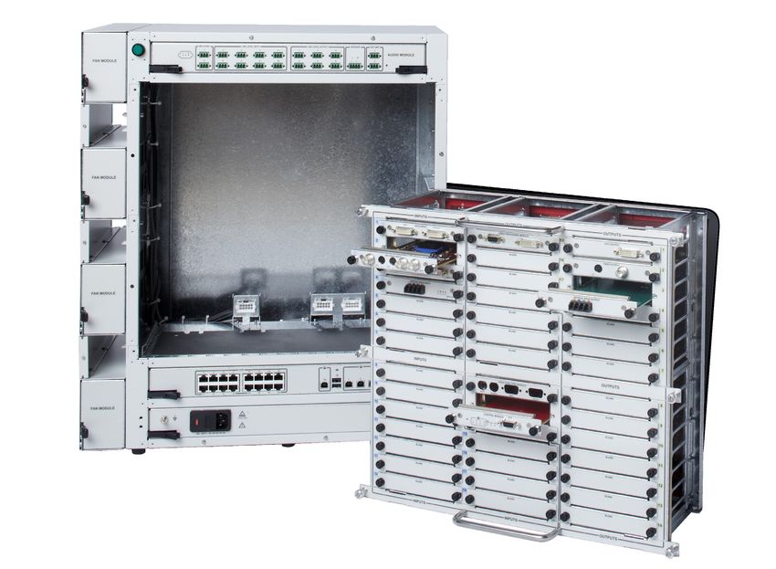
SWITCHPOINT INFINITY 3 (A1)
Dimensions • Media Router: 20.6"W x 24"H x 17"D
• Control Section: 12.5"W x 2.6"H x 17"D
• Total Space Required: 27.5"W x 31"H x 29"D
Data One (1) Ethernet connection
Back Box • One (1) 18"W x 18"H x 4"D (or larger) junction box flush mounted.
• Set bottom of box 9" above finished floor.
• Terminate all integration conduits to this junction box.
16S
SPI3-LITE (A4)
Dimensions • Media Router: 16.4"W x 15.3"H x 17.4"D
• Control Section: 12.5"W x 2.6"H x 17"D
• Total Space Required: 27.5"W x 31"H x 29"D
Data One (1) Ethernet connection
Back Box • One (1) 18"W x 18"H x 4"D (or larger) junction box flush mounted.
• Set bottom of box 9" above finished floor.
• Terminate all integration conduits to this junction box.
SPI3 TOUCH PANEL, 22" (B1)
Dimensions 20.3"W x 15.8"H x 13.5"D with stand
SPI3 TOUCH PANEL, 19" (C)
Dimensions 17.7"W x 15"H x 11.8"D with stand
SWITCHPOINT INFINITY 2 (A2)
Dimensions • Router: 21.0"W x 24.0"H x 22.3"D
• Total space required: 27.5"W x 31"H x 29"D
Data One (1) Ethernet connection
Back Box • One (1) 18"W x 18"H x 4"D (or larger) junction box flush mounted.
• Set bottom of box 9" above finished floor.
• Terminate all integration conduits to this junction box.
SPI2 TOUCH PANEL, 19" (B2)
Dimensions 16.9"W x 15.5"H x 8.2"D with stand
SWITCHPOINT ELEMENT (A3)
Dimensions • Video Router: 12.5"W x 10"H x 15"D
• Control System: 12.5"W x 2"H x 15"D
• Total Space Required: 27.5"W x 31"H x 29"D
Data One (1) Ethernet connection
Back Box • One (1) 18"W x 18"H x 4"D (or larger) junction box flush mounted.
• Set bottom of box 9" above finished floor.
• Terminate all integration conduits to this junction box.
SPE TOUCH PANEL, 12" (B3)
Dimensions 11.9"W x 11.3"H x 6.6"D with stand
SUITESTREAM CODEC (D)
Dimensions 12.7"W x 2.6"H x 17.3"D
17S
Data • Two (2) Ethernet connections
• Please refer to Stryker ConnectSuite Pre-Install document,
SOP0304.08 for specific network requirements..
SDC ULTRA (F)
Dimensions 12.5"W x 7"H x 16.2"D
Data One (1) Ethernet connection
SDP1000 PRINTER (H)
Dimensions 12.5"W x 8.2"H x 16.7"D
SIDNE (I)
Dimensions 12.6"W X 4.5"H X 16.2"D
WISE TRANSMITTER (J)
Dimensions 12.5"W X 3.3"H X 15.2"D
NAVIGATION PC (K)
Dimensions 17"W X 20"H X 24"D
Data One (1) Ethernet connection
HD CODEC (L)
Dimensions 5.1"W X 13.9"H X 11"D
Data • One (1) Ethernet connection
• Please consult project manager if ISDN is utilized
SD CODEC (L1)
Dimensions 19.5"W X 2"H X 12"D
Data One (1) Ethernet connection
Please consult project manager if ISDN is utilized
WIRELESS MICROPHONE RECEIVER (M)
Dimensions 8.3"W X 1.93"H X 7.2"D
VISUM HALOGEN POWER SUPPLY BOX (N)
Dimensions • PSB: 17.8"W X 6"H X 15.8"D
• Total Space Required: 20"W X 9"H X 21"D
Back Box • One (1) 6"W x 6"H x 4"D (or larger) junction box flush mounted.
• Set bottom of box 14" above finished floor.
• Terminate all surgical light conduits to this junction box
18S
VISUM LED POWER SUPPLY BOX (N1)
Dimensions • PSB: 12.5"W X 7"H X 15.5"D
• Total Space Required: 20"W X 9"H X 21"D
Back Box • One (1) 6"W x 6"H x 4"D (or larger) junction box flush mounted.
• Set bottom of box 14" above finished floor.
• Terminate all surgical light conduits to this junction box
5.4 iSuite Equipment Integration Notes
Note All conduit runs include insulated bushings and pull strings.
Note Conduit runs cannot exceed 50' from end-to-end. Do not exceed four (4) 90 de-
gree bends.
5.4.1 Wall Mounted 46" or 55" LCD Monitor or 42" TouchPanel
Conduit One (1) 1 1/4" conduit
Back Box • 4"W X 4"H junction box with single-gang mud ring
• Mounted directly above the top of the mounting bracket.
Power One (1) standard duplex outlet mounted adjacent to junction box
Structural • Customer/Contractor to mount Stryker provided bracket to the wall in the de-
sired location with proper reinforcement to support the monitor prior to Stryker
installation.
• Stryker Project Manager will provide mounting specifications.
ITEM-ITEM QTY SIZE
WMM – A 1 1 1/4"
5.4.2 Wall/Ceiling Mounted Room Status Camera (WRC, CRC) LA
Conduit One (1) ¾" conduit terminated at nearest corridor cable tray
Back Box • 4"W x 4"H junction box with single-gang mud ring
• Flush mounted at 12" below finished ceiling (wall mounted only)
Power None
Cabling • One (1) power cable and one (1) video cable
• One (1) Belden 8723 / 88723 (maximum 1000')
• One (1) Belden 8241 / 88241 (maximum 1000')
• Cables require 15' service loop at both ends
Note All Status System cabling must be provided and pulled by the Hospital/Contrac-
tor prior to Stryker Installation.
19S
ITEM-ITEM QTY SIZE
WRC/CRC – * 1 ¾"
5.4.3 Wall Plates
Conduit One (1) ½" conduit
Back Box • 4"W x 4"H junction box with single-gang mud ring
• 4"W x 4"H junction box with dual-gang mud ring (Fiber optical DVI only)
• Mounted 48" above finished floor.
Power None required, but should be located next to outlet
ITEM-ITEM QTY SIZE
Copper DVI (CDP) – A 1 1 ½"
VGA/S-Video/BNC (TRP) - A 1 1"
Pass-Through (PTP) - A 1 1"
Fiber Optical DVI - A 1 1"
5.4.4 Observation Room Touch Panel, Microphone and Speaker (OBS) LA
Conduit One (1) 1" conduit terminated
Cabling For runs over 50', Hospital/Contractor provides the following:
• Two (2) Belden 8723 / 88723 (maximum 1000')
• One (1) CAT6 cable (maximum 328')
• Cables require 15' service loop at both ends
• Cabling provided and pulled by Hospital/Contractor before Stryker installation
Back Box • 4"W x 4"H junction box with single-gang mud ring
• Mounted within 18" of touch panel location
Power One (1) standard outlet within 18" of touch panel location
ITEM-ITEM QTY SIZE
OBS – A 1 1"
5.4.5 Cable Run to Video Network Hub (HRN)
Conduit One (1) 2" conduit terminated at nearest corridor cable tray.
Cabling • Four (4) Belden 8241/88241 or equivalent (maximum 1000' - consult Project Man-
ager for runs over 1000')
• Two (2) Belden 8723 / 88723 or equivalent (maximum 1000' - consult Project Man-
ager for runs over 1000')
• One (1) CAT6 cable (maximum 328' - consult Project Manager for runs over 328'))
• Cables require 15' service loop at both ends
• Hub cabling provided and pulled by Hospital/Contractor before Stryker installation
ITEM-ITEM QTY SIZE
HRN – * 1 2"
20S
5.4.6 Equipment Boom Cable Kit (Brand) (EQB)
Cabling All cabinets within the boom must be pulled by Hospital/Contractor if not already
pulled by boom manufacturer
Conduit Terminated within 18" of the center of the ceiling mount
Power Per boom manufacturer specifications
Plumbing Per boom manufacturer specifications
Access Panel One (1) 24" x 24" access panel adjacent to suspension
Structural Per boom manufacturer specifications
ITEM-ITEM QTY SIZE
EQB – A 2 2"
5.4.7 Anesthesia Boom Cable Kit (Brand) (ANB)
Cabling All cables within the boom must be pulled by Hospital/Contractor if not already
pulled by boom manufacturer
Conduit Terminated within 18" of the center of the ceiling mount
Power Per boom manufacturer specifications
Plumbing Per boom manufacturer specifications
Access Panel One (1) 24" x 24" access panel adjacent to suspension
Structural Per boom manufacturer specifications
ITEM-ITEM QTY SIZE
ANB – A 1 2"
5.4.8 Navigation Arm (NAM)
Conduit Terminated to 10" x 10" x 4" NEMA type 1 box within 18" of the center of the ceiling
mount.
Power No additional power required.
Access Panel One (1) 24" x 24" access panel adjacent to suspension
Structural • Optimal location for center of Navigation camera is 47" above finished floor.
• Stryker preinstall plate is installed per customer structural engineer specs at 4"
above finished ceiling.
• A 21" circular hole centered on Stryker preinstall plate in the finished ceiling is
required for installation. A 24" diameter ceiling cover conceals hole after suspen-
sion is installed.
• The Contractor/electrician to hardwire Stryker electrical whip during Stryker
installation.
• Load location: X=31", Y=45"
• Maximum deflection: 1 degree
ITEM-ITEM QTY SIZE
NAM – A 1 2"
21S
5.4.9 Stryker Single Flat Panel Arm Cable Kit
Conduit One (1) 2" (50mm) conduit terminated with insulated bushings within 18" (450mm)
of the center of the ceiling mount. This conduit must be accessible from the access
panel and terminated in a horizontal orientation. Pull strings should be provided.
Power One (1) - 20 AMP circuit located at junction box within 18" of center of Stryker pre-
install plate. Hospital/Contractor should hardwire during installation.
Access Panel One (1) 24" x 24" access panel adjacent to suspension
5.4.10 Stryker Dual Flat Panel Arm Cable
Conduit One (1) 2" (50mm) conduit terminated with insulated bushings within 18" (450mm)
of the center of the ceiling mount. This conduit must be accessible from the access
panel and terminated in a horizontal orientation. Pull strings should be provided.
Power One (1) - 20 AMP circuit located at junction box within 18" of center of Stryker pre-
install plate. Hospital/Contractor should hardwire during installation.
Access Panel One (1) 24" x 24" (610mm x 610mm) access panel adjacent to suspension
5.4.11 Single Flat Panel Arm Cable Kit (Non-Stryker Flat Panel Arm) (NAM)
Conduit Two (2) 2" (50mm) conduit terminated with insulated bushings within 18" (450mm)
of the center of the ceiling mount. This conduit must be accessible from the access
panel and terminated in a horizontal orientation. Pull strings should be provided.
Power Two (2) - 20 AMP circuit located at junction box within 18" of center of Stryker pre-
install plate. Hospital/Contractor should hardwire during installation.
Access Panel One (1) 24" x 24" (610mm x 610mm) access panel adjacent to suspension
5.4.12 Dual Flat Panel Arm Cable Kit (Non-Stryker Flat Panel Arm)
Conduit Two (2) 2" (50mm) conduit terminated with insulated bushings within 18" (450mm)
of the center of the ceiling mount. This conduit must be accessible from the access
panel and terminated in a horizontal orientation. Pull strings should be provided.
Power Two (2) - 20 AMP circuit located at junction box within 18" of center of Stryker pre-
install plate. Hospital/Contractor should hardwire during installation.
Access Panel One (1) 24" x 24" (610mm x 610mm) access panel adjacent to suspension
22S
6. Infinity Based Conference System (IBC) Rooms LA
Note All cabling must be provided and pulled by Hospital/Contractor prior to Stryker's
arrival.
IBC's are most often installed in auditoriums, classrooms, and large conference rooms. The IBC can be
installed in a variety of places. The control system can either sit in a closet or in the back of the room.
A podium is recommend to accommodate the IBC Touch Panel and cable runs to the control system.
6.1 SPI3 Customer Supplied Casework (SCW)
Data Per listed equipment
Back Box Per listed equipment
Power Recommended two (2) - 20 amp circuits:
• One (1) circuit for quad outlet behind video router
• One (1) circuit for quad outlet behind support equipment
Space • Casework must allow for a minimum 2" cable passage between all compo-
Requirements nents housed inside.
• Section housing video router must have an interior dimension of at least
27.5"W X 31"H X 29"D.
• Section housing video router must be vented.
• Must allow for direct access to backboxes per requirements listed below.
6.2 IBC Unit with Tower (ICW1) LA
Dimensions 27.5"W X 65"H X 30"D
Data One (1) Ethernet connection
Back Box • One(1) 18"W X 18"H X 4"D (minimum) junction box flush mounted.
• Set bottom of the box 9" above finished floor within the footprint of the tower.
• Terminate all integration conduits to this junction box.
• Hospital/Contractors will provide and pull all cables.
Power One (1) - 20 AMP circuit for quad outlet behind the tower.
6.3 IBC Unit with Stryker Credenza (ICW2) LA
Data One (1) Ethernet connection
Back Box • One(1) 18"W X 18"H X 4"D (minimum) junction box flush mounted.
• Set bottom of the box 9" above finished floor within the foot print of the tower.
• Terminate all integration conduits to this junction box.
• Hospital/Contractor will provide and pull all cables.
Power One (1) - 20 amp circuit for quad outlet behind the tower.
Note Customer/Contractor responsible for receiving and installing Credenza prior to
Stryker installation.
23S
6.4 IBC with Customer Supplied Casework (ICW3) LA
Data Per listed equipment
Back Box • One(1) 18"W X 18"H X 4"D (minimum) junction box flush mounted.
• Set bottom of the box 9" above finished floor within the foot print of the tower.
• Terminate all integration conduits to this junction box.
• Hospital/Contractor will provide and pull all cables.
Power • One (1) - 20 amp circuit for outlets behind video router.
• One (1) - 20 amp circuit for quad outlet behind casework.
Space • Must allow for a minimum 2" cable passage between all components housed
Requirements inside.
• Section housing video router must have an interior dimension of at least
27.5"W X 31"H X 29"D.
• Section housing the video router must be vented.
• Must allow for direct access to backboxes per requirements listed below.
Note Customer/Contractor responsible for installation of casework prior to Stryker
installation.
6.5 Casework Equipment
6.5.1 SwitchPoint Infinity 2 (A2) LA
Dimensions • Router 19.5"W X 28.5"H X 23"D
• Total Space Required: 27.5"W X 31"H X 29"D
Data One (1) Ethernet connection
Back Box • One(1) 18"W X 18"H X 4"D (minimum) junction box flush mounted.
• Set bottom of the box 9" above finished floor.
• Terminate all integration conduits to this junction box.
Power One (1) standard outlet within 3'.
6.5.2 SPI2 Touch Panel, 19" (B2)
Dimensions 16.9"W X 15.5"H X 8.2"D with stand
Power One (1) standard outlet within 3'
6.5.3 Wireless Microphone Receiver (M)
Dimensions 8.3"W X 1.93"H X 7.2"D
Power One (1) standard outlet within 3'
24S
6.5.4 SD CODEC (L1)
Dimensions 19.5"W X 2"H X 12"D
Data • One (1) Ethernet connection
• Please consult Project Manager if ISDN is utilized.
Power One (1) standard outlet within 3'
6.6 IBC Podium with Touch Panel LA
Note Customer/Contractor responsible for installation of podium prior to Stryker
installation.
Dimensions 32"W X 46"H X 24.3"D
Cabling • Cables provided by the Hospital/Contractor for runs over 50'.
• Cables pulled by the Hospital/Contractor.
• Leave a 15' (4.5m) service loop at each end for terminations.
• Cable Specifications: Cables may vary depending on conference room configu-
rations. Please consult Project Manager for site specific requirements:
• Touch Panel:
ºº One (1) Belden 8723 or equivalent (maximum 1000')
ºº One (1) Extron MHR5 or equivalent (maximum 150')
• Laptop Connection:
ºº One (1) Belden 8723 or equivalent (maximum 1000')
ºº One (1) Extron MHR5 or equivalent (maximum 150')
• PC Connection:
ºº One (1) Belden 8723 or equivalent (maximum 1000')
ºº One (1) Extron MHR5 or equivalent (maximum 150')
• Podium Microphone
ºº One (1) Belden 8723 or equivalent (maximum 1000')
• Network
ºº Two (2) CAT6 cables (maximum 328')
Conduit Two (2) 2" conduits
Back Box • 12"W X 12"H junction box
• Flush mounted in the floor under the podium
Power • One (1) standard outlet
• Flush mounted in the floor beneath podium adjacent or within 12" X 12" junc-
tion box
ITEM-ITEM QTY SIZE
IPD – ICW 2 2"
25S
7. Level Systems Room
Note All cabling must be provided and pulled by Hospital/Contractor prior to Stryker's
arrival.
Level System's are most often installed in integrated doctor's offices, small conference rooms, and
pathology or nuclear medicine labs. This control system is placed in a cabinet next to or in the room's
cabinetry or desk. Cable passage must be allowed to the junction box for all equipment placed on the
desk or in the cabinetry.
7.1 Customer Supplied Casework (CSC)
Data Per listed equipment
Back Box Per listed equipment
Power One (1) - 20 amo circuit for outlets behind video router
Space • Must allow for a minimum 2" cable passage between all components housed
Requirements inside.
• Section housing video router must have an interior dimension of at least 21"W
X 16"H X 22"D
• Section housing router must be vented.
• Must allow for direct access to back boxes per requirements listed below.
Note Customer/Contractor responsible for installation of casework prior to Stryker
installation.
7.2 Casework Equipment
7.2.1 Level One System (S1) LA
Dimensions 20.5"W X 8.5"H X 16"D
Data None
Back Box • One (1) 6"W X 6"H X 4"D (minimum) junction box flush mounted at
same height as Level System
• Terminate all integration conduits to this junction box
Power One (1) duplex outlet next to junction box
7.2.2 Level Two System (S2) LA
Dimensions 20.5"W X 14"H X 19"D
Data None
Back Box • One(1) 12"W X 12"H X 4"D (minimum) junction box flush mounted at
same height as Level System
• Terminate all integration conduits to this junction box
Power One (1) duplex outlet next to junction box
26S
7.2.3 Level System Touch Panel (T)
Dimensions • Touch Panel: 11.9"W X 11.3"H X 6.6"D
• Touch Panel Interface: 19"W X 2"H X 11"D
Power One (1) duplex outlet
7.3 Remote Level System Touch Panel (LTP)
Dimensions • Touch Panel: 11.9"W X 11.3"H X 6.6"D
• Touch Panel Interface: 19"W X 2"H X 11"D
Cabling • Cables provided by the Hospital/Contractor for runs over 50'
• Cables pulled by the Hospital/Contractor
• Leave a 15' (4.5m) services loop at each end for terminations
• Cable Specifications:
ºº Three (3) Belden 8723 or equivalent (maximum 1000')
ºº One (1) Belden 8241 or equivalent (maximum 1000')
Conduit One (1) 1" conduit
Back Box • 4"W X 4"H junction box with single-gang mud ring
• Mounted within 18" of touch panel location
Power One (1) standard outlet within 18" of touch panel location
ITEM-ITEM QTY SIZE
LTP – S 1 1"
27You can also read