HydroShear DNA Shearing Device - Work Less. Do More - User Manual
←
→
Page content transcription
If your browser does not render page correctly, please read the page content below
Work Less. Do More.            ™

HydroShear® DNA
 Shearing Device
     User Manual

              P/N: HSH114005   Revision B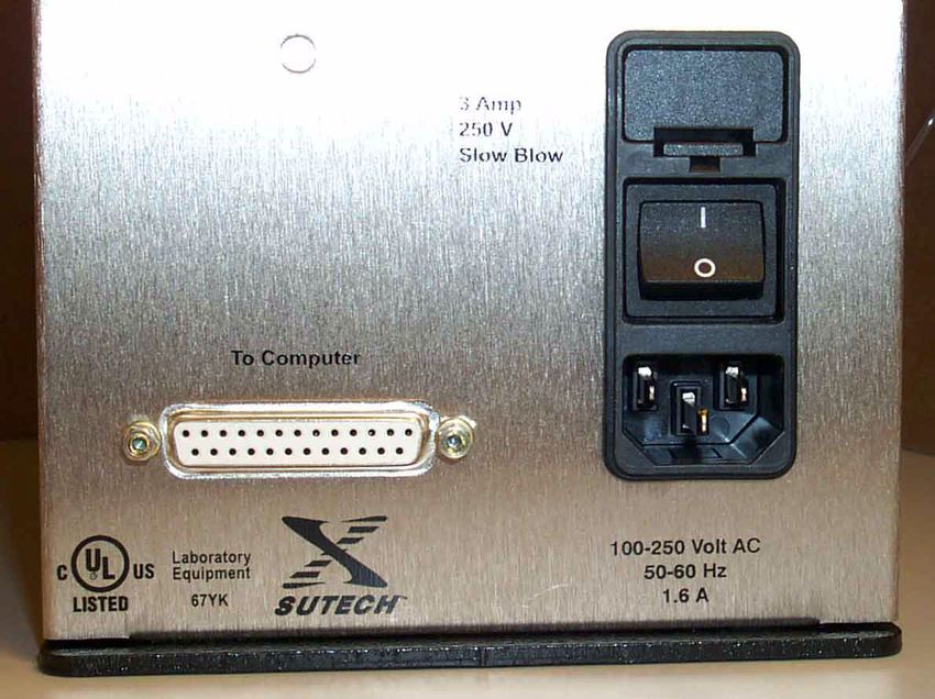
HydroShear® DNA Shearing Device

Serial Number
Software Version
Owned By

Date Installed
Service Contract Type
Service Contract Dates

 Service Record
                                                                               Contacted
                                                                               GeneMachines?
Date               Concern                    Action Taken                     (name?)

GeneMachines                      1-877-855-GENE (4363)
935 Washington St.                1-650-508-1644
San Carlos, CA 94070              support@genemachines.com

                                 HydroShear® DNA Shearing Device User Manual                   3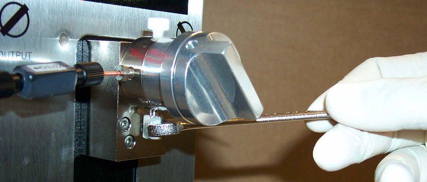
© 2000 - 2001 Genomic Instrumentation Services, Inc. All rights reserved.
No part of this publication may be reproduced, transcribed, transmitted, or translated into any language, in any form, and by any means without the
written permission of Genomic Instrumentation Services, Inc.
Important notice:
GeneMachines believes that the information in this document is accurate. The document has been carefully reviewed for technical accuracy. In the
event that technical or typographical errors exist, GeneMachines reserves the right to make changes to subsequent editions of this document
without prior notice to holders of the edition. The reader should consult GeneMachines if errors are suspected. IN NO EVENT SHALL
GENEMACHINES BE LIABLE FOR ANY DAMAGE ARISING OUT OF OR RELATED TO THIS DOCUMENT OR THE
INFORMATION CONTAINED IN IT.
Trademarks

GeneMachines®, HydroShear® DNA Shearing Device

GeneMachines® is a registered trademark of Genomic Instrumentation Services, Inc in the U.S. and some countries. HydroShear® DNA Shearing
Device is a trademark of Genomic Instrumentation Services, Inc.
Windows® is a registered trademark of Microsoft Corporation. Pentium® and Pentium III® are registered trademarks of Intel Corporation.

GeneMachines Software License
General: All sales by Genomic Instrumentation Services, Inc. (the “Company”) of its products, including hardware components (“Instrument”)
and software (“Software”) incorporated therein (collectively, the “Products”), to its original owner (“Customers”) are subject to the following
terms and conditions (“Terms and Conditions”). “Instrument” means the tangible, physical components of Products, specifically the HydroShear®
DNA Shearing Device. “Software” means any software or related documentation incorporated into the Products or provided under a separate
agreement. “Customer” means any person who purchases Products directly from Company or one of its authorized distributors for internal use and
is the original owner of the Product.
Software license: The software is furnished to Customer under a nonexclusive license for use only on the single unit of Product for which the
Software is provided. Such Software may not be used on or with any other products or for activities ourside the scope of this Agreement without
the prior written permission of the Company. Customer acknowledges that the Software constitutes valuable proprietary, confidential and trade
secret information of the Company, or of third party suppliers of Software, as the case may be. Such Software may not be copied in whole or in
part, or sublicensed, provided, transferred or otherwise disclosed or made available to third parties without the express prior written permissions of
the Company or such third party Software supplier, as the case may be. Customer will notify the Company promptly of any unauthorized use,
possession, knowledge, Company or such third party Software supplier, as the case may be. If requested by the Company, Customer will execute
and deliver a standard form or license agreement issued by the Company supplier with respect to any Software provided hereunder that is owned
and licensed by such supplier.
The software is protected by United States Copyright Law and International Treaty provisions. Under the copyright laws, this Software may not be
reproduced or transmitted in any form, electronic or mechanical, including photocopying, recording, storing in an information retrieval system, or
translating in whole or in part, without the prior written consent of Company. Trademarks shall be used in accordance with accepted trademark
practice, including identification of trademark owners’ names. These Term and Conditions do not grant the Customer any intellectual property
rights in this Software.

4
                                                         Work Less. Do More.™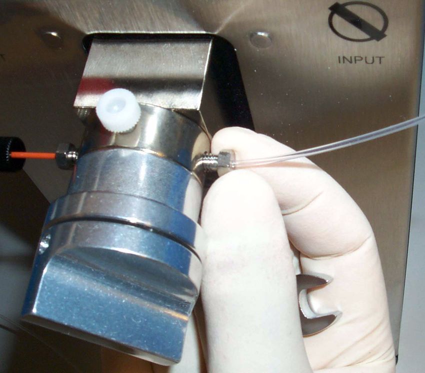
Table of Contents

1. About the HydroShear® DNA Shearing Device ............................................9
             1.1 The Components .............................................................................................. 9
             1.2 Technical Specifications .................................................................................. 9
             1.3 Facility and Hardware Requirements ............................................................ 10
                                1.3.1 Electrical Requirements ............................................................................... 10
                                1.3.2 Computer/Software Requirements ............................................................... 10
                                1.3.3 Environmental Requirements....................................................................... 10
             1.4 Contacting GeneMachines®.......................................................................... 10

2. HydroShear® DNA Shearing Device Design and Shearing Method............13
             2.1 Design of the HydroShear DNA Shearing Device ........................................ 13
                                2.1.1 Shearing Orifice ........................................................................................... 13
                                2.1.2 Pump System................................................................................................ 13
                                2.1.3 Valve System ................................................................................................ 14
                                  Figure 2-1: Valve Knob Orientations ............................. 14
             2.2 Shearing Method............................................................................................ 15
                                  Figure 2-2: Solution Flow Through the Orifice .............. 15

3. Performance Data ..........................................................................................17
             3.1 Summary ........................................................................................................ 17
             3.2 Fragment Size is Correlated with Pump Speed ............................................. 17
                                       Figure 3-1: Fragment Size is Correlated with Pump Speed 18
             3.3 Sample Boundaries ........................................................................................ 18
                                3.3.1 Smallest Initial Fragment Size that Can Be Sheared.................................... 18
                                                Figure 3-2: Smallest Initial Fragment Size that Shears .. 19
                                3.3.2 Smallest Sample Volume that Can Be Sheared ............................................ 19
                                            Figure 3-3: Smallest Volume that Can Be Sheared ........ 20
             3.4 Smallest Fragments the HydroShear DNA Shearing Device Can Repeatedly Pro-
                 duce ................................................................................................................ 21
                                            Figure 3-4: Smallest Consistently-Produced Fragment Range
21
             3.5 Independence of Shearing Performance ........................................................ 21
                                3.5.1 No Effect of Initial Fragment Length........................................................... 22
                                                Figure 3-5: Effect of Initial Fragment Length on Shearing 22
                                3.5.2 No Sample Volume Effect ............................................................................ 22
                                                Figure 3-6: Effect of Sample Volume on Fragment Size 23

                                                   HydroShear® DNA Shearing Device User Manual                                                           5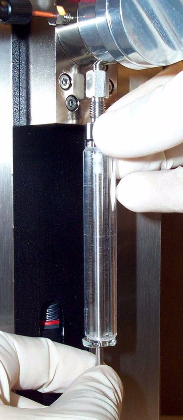
3.5.3 No DNA Concentration Effect ..................................................................... 23
                                                  Figure 3-7: Effect of DNA Concentration on Shearing .. 24
                                 3.5.4 No User, User Skill, or Sequence Effect ...................................................... 24
                                                  Figure 3-8: Consistency of Shearing Across Users and Days 25

4. Installing the HydroShear DNA Shearing Device ........................................27
              4.1 Finding a Location for the HydroShear DNA Shearing Device .................... 27
              4.2 Syringe Installation ........................................................................................ 27
                                     Figure 4-1: Installing the Syringe ................................... 28
              4.3 Hardware Installation..................................................................................... 29
                                     Figure 4-2: Power and Serial Connections ..................... 29
              4.4 Software Installation ...................................................................................... 29
              4.5 Shearing Assembly Installation ..................................................................... 30
                                 4.5.1 Shearing Assembly Components ................................................................. 30
                                                  Figure 4-3: A Shearing Assembly .................................. 30
                                 4.5.2 Determining the Correct Orientation of an Unlabeled Orifice Box ............. 31
                                 4.5.3 Attaching the Shearing Assembly to the HydroShear DNA Shearing Device32
                                                  Figure 4-4: Attaching the Shearing Assembly to the Base Unit
32
                                                  Figure 4-5: Tightening the Base Screw .......................... 32
                                 4.5.4 Calibrating the Shearing Assembly.............................................................. 33
                                                  Table 1: Typical Size to Speed Code Correlation........... 33

5. Software ........................................................................................................35
              5.1 Starting the HydroShear DNA Shearing Device Software ............................ 35
                                    Figure 5-1: HydroShear DNA Shearing Device Main Panel 36
              5.2 A Tour of the HydroShear DNA Shearing Device Main Panel..................... 36
              5.3 Shearing Parameters ...................................................................................... 37
                                 5.3.1 Basic Shearing Parameters Defined ............................................................. 37
                                     5.3.1.1 Volume................................................................................................................ 37
                                     5.3.1.2 Number of Cycles............................................................................................... 37
                                     5.3.1.3 Speed Code......................................................................................................... 38
                                 5.3.2 Editing Basic Shearing Parameter Values .................................................... 38
                                 5.3.3 The Wash Scheme ........................................................................................ 38
                                 5.3.4 Saving Shearing Parameters Values to a File ............................................... 39
                                 5.3.5 Saving New Shearing Parameter Default Values ......................................... 39
                                 5.3.6 Restoring Shearing Parameter Default Values ............................................. 40
              5.4 Operation Controls......................................................................................... 40
              5.5 Status.............................................................................................................. 41
              5.6 Machine Parameters....................................................................................... 41
                                            Figure 5-2: Machine Parameters window ....................... 42
                                 5.6.1 The Machine Parameters Defined ................................................................ 42

6
                                                         Work Less. Do More.™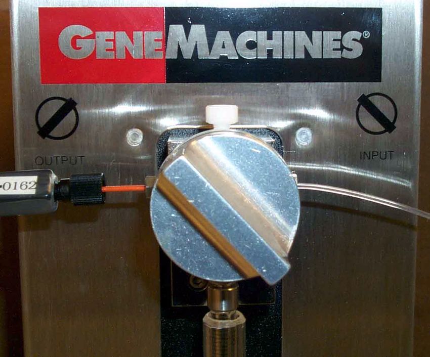
5.6.1.1 Syringe Volume .................................................................................................. 42
                                      5.6.1.2 Void Volume ....................................................................................................... 42
                                      5.6.1.3 Retraction Speed................................................................................................. 43
                                      5.6.1.4 Residual Volume................................................................................................. 43
                                      5.6.1.5 Port Number ....................................................................................................... 43
                                  5.6.2 To Edit Machine Parameter Values .............................................................. 43
                                  5.6.3 To Save as New Default Values ................................................................... 43
                                  5.6.4 To Restore Machine Parameter Default Values............................................ 44
                                  5.6.5 To Restore Factory-Set Machine Parameter Default Values ........................ 44

6. Shearing.........................................................................................................45
         6.1 Set Shearing Parameters ................................................................................ 45
         6.2 Filter Wash Solutions..................................................................................... 46
                                            Table 1: HydroShear DNA Shearing Device Solution Set (Order
#HSA-Kit-1) ......................................................................................................................... 46
         6.3 Prepare the Sample ........................................................................................ 46
         6.4 Shear the Sample ........................................................................................... 47
                                            Figure 6-1: Valve Handle in the Input Position .............. 47
                                            Figure 6-2: Valve Handle in the Output Position ........... 47
         6.5 Conducting the Wash Scheme ....................................................................... 49

7. Manual Operation..........................................................................................53
                                       Figure 7-1: Manual Operation Window .......................... 53
               7.1 Manual Operation: The Basics ...................................................................... 53
               7.2 Drawing Volume into the Pump .................................................................... 54
               7.3 Ejecting Fluid from the Pump........................................................................ 54
               7.4 Reinitializing the Pump ................................................................................. 55

8. Maintenance ..................................................................................................57
               8.1 Routine........................................................................................................... 57
                                  8.1.1 Daily Maintenance Guidelines ..................................................................... 57
                                  8.1.2 Periodic Cleaning ......................................................................................... 57
                                      8.1.2.1 Cleaning with Weak Detergent........................................................................... 57
                                      8.1.2.2 Cleaning with Weak Acid and Base in Sequence............................................... 58
                                      8.1.2.3 Cleaning with 10% Bleach ................................................................................. 58
               8.2 Periodic Maintenance .................................................................................... 59
                                  8.2.1 Unclogging Shearing Orifices -- Sonication Protocol.................................. 59
                                  8.2.2 Replacing Tubing ......................................................................................... 61
                                      8.2.2.1 Replacing the Output Tube................................................................................. 61
                                                   Figure 8-1: Connecting a New Output Tube to the Orifice Box
61
                                      8.2.2.2 Replacing the Input Tube ................................................................................... 62

                                                      HydroShear® DNA Shearing Device User Manual                                                                      7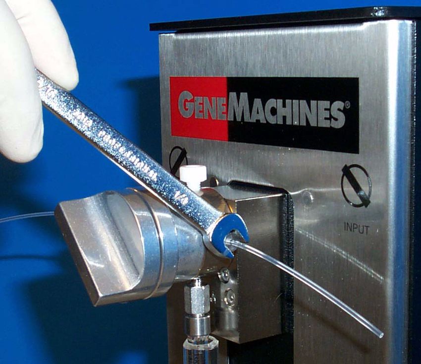
Figure 8-2: Replacing the Input Tube ............................. 62
                               8.2.3 Syringe Maintenance.................................................................................... 63
                                   8.2.3.1 Removing the Syringe ........................................................................................ 63
                                               Figure 8-3: Removing the Syringe .................................. 63
                                   8.2.3.2 Replacing the Syringe Adapter........................................................................... 64
                                               Figure 8-4: Replacing the Syringe Adapter .................... 65
                               8.2.4 Lead Screw Maintenance ............................................................................. 65
                                   8.2.4.1 Lubricating the Lead Screw ............................................................................... 65
                               8.2.5 Valve Maintenance ....................................................................................... 65
                                   8.2.5.1 Replacing the Valve Assembly........................................................................... 65

9. Troubleshooting.............................................................................................67
             9.1 Error Messages .............................................................................................. 67
                               9.1.1 Message: Error 37 Occurred at Serial Port................................................... 67
                               9.1.2 Reading Time Out ........................................................................................ 67
                               9.1.3 Pump Overload or Plunger Overload ........................................................... 67
                               9.1.4 Other Error Messages................................................................................... 67
             9.2 Problems Visible During Shearing ................................................................ 68
                               9.2.1 I see a bubble inside the syringe................................................................... 68
                               9.2.2 I see an air bubble in the syringe when the sample is retracted from the output
                               tube. ....................................................................................................................... 68
                               9.2.3 I see frothy bubbles in the sample when it leaves the orifice....................... 68
                               9.2.4 The sample is retracted back into the syringe (from the output tube) at a sporadic
                               rate......................................................................................................................... 68
                               9.2.5 The sample continues to move after the syringe has finished retracting. .... 69
                               9.2.6 The volume of sample seems to be decreasing. ........................................... 69
             9.3 Sample and Fragment Problems .................................................................... 69
                               9.3.1 DNA is lost................................................................................................... 69
                               9.3.2 The fragments produced aren’t the right size............................................... 69
                               9.3.3 The fragments produced do not clone well. ................................................. 70

8
                                                      Work Less. Do More.™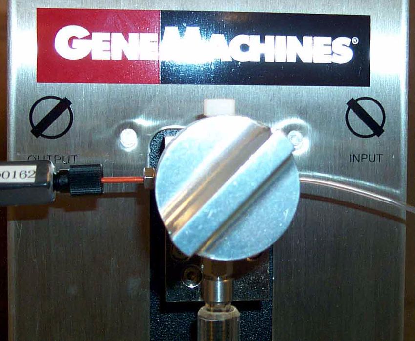
About the HydroShear® DNA Shearing Device

1.   About the HydroShear® DNA Shearing
             Device

The Hydroshear DNA Shearing Device is an automated, Point-sink Shearer (PtS), offering a simple, reproducible,
and controllable method of fragmenting DNA. The Hydroshear DNA Shearing Device creates and controls
hydrodynamic forces that work in conjunction with its innovative shearing assembly to consistently and repeatably
shear DNA. A wide range of DNA samples are compatible with the Hydroshear DNA Shearing Device, and the
shearing parameters can be adjusted to produce specific fragment lengths of DNA.

1.1 THE COMPONENTS
Each Hydroshear DNA Shearing Device comes complete with the following:
        • HydroShear DNA Shearing Device base unit
        • 500 µL syringe
        • Four #025 shearing assemblies
        • Power cord
        • RS-232 cord and connectors
        • Software
        • Tool kit

1.2 TECHNICAL SPECIFICATIONS
•   Fuse Current Rating: 3 Amps
•   Fuse Voltage Rating: 250V
•   Voltage: 100-250 VAC
•   Frequency Range: 47-100 Hz
•   Installation (Over voltage) Category: II

                                          HydroShear® DNA Shearing Device User Manual                           9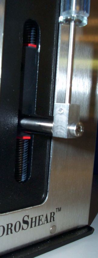
1.3 FACILITY AND HARDWARE REQUIREMENTS

1.3.1 Electrical Requirements
• One properly grounded 110V / 15 amp or 220V / 10 amp wall outlet

1.3.2 Computer/Software Requirements
The Hydroshear DNA Shearing Device software can be installed on any PC fulfilling the following requirements:
         • IBM-compatible
         • Operating system: Microsoft Windows 3.11, 95, 98, or NT
         • One serial port available to connect to the Hydroshear DNA Shearing Device base unit

1.3.3 Environmental Requirements
•    Pollution Degree: 2
•    Installation Category: II
•    Altitude: any up to 2000 m
•    Temperature Operating (mechanism): 59°F (15°C) to 104°F (40°C)
•    Humidity Operating (mechanism): 20-95%RH at 104°F (40°C)

1.4 CONTACTING GENEMACHINES®
Please contact GeneMachines directly with questions about operating and maintaining the Hydroshear DNA Shearing
Device or if your Hydroshear DNA Shearing Device requires servicing. To help us assist you, please provide the
following information:

         • The unit serial number (located on the machine’s back panel)
         • The name of your company or institution
         • Your name and contact information
         • A full description of the problem

10
                                               Work Less. Do More.™
About the HydroShear® DNA Shearing Device
Phone: 1-877-855-GENE (4363), 1-650-508-1634
Fax: 1-650-508-1644
E-mail: support@genemachines.com (please include “Hydroshear DNA Shearing Device” in subject line)
Address:
GeneMachines
Attn. Hydroshear DNA Shearing Device Customer Support
935 Washington Street
San Carlos, CA 94070
HydroShear® DNA Shearing Device User Manual 1112
Work Less. Do More.™HydroShear® DNA Shearing Device Design and Shearing Method
2. HydroShear® DNA Shearing Device
Design and Shearing Method
As the DNA samples are accelerated through a narrow orifice, drag forces shear the DNA
molecules apart.
2.1 DESIGN OF THE HYDROSHEAR DNA SHEARING
DEVICE
The innovative design of the HydroShear DNA Shearing Device appropriates hydrodynamic forces and a one-way,
flow-though orifice to fragment DNA. This design is based on the hydrodynamic point-sink shearing method
originally developed by Oefner et al. (1996)1; “point-sink” refers to a theoretical model of the hydrodynamic flow
through such a system.
2.1.1 Shearing Orifice
In order to accomplish accurate, reproducible shearing, the HydroShear DNA Shearing Device utilizes a precision-
drilled ruby as its shearing orifice.
The ruby is mounted inside the orifice box, which is connected by tubing to the valve system.
(See 4.5.1 Shearing Assembly Components, page 30 for a detailed description of the shearing assembly).
2.1.2 Pump System
The HydroShear DNA Shearing Device employs a syringe pump system. Air and fluid flow is pressure-controlled by
the movement of the plunger inside the glass syringe. The pump will “stall” at a certain pressure; at this pressure, the
pump’s functions can be accomplished without promoting leakage throughout the pump and valve system.
1. Oefner, P.J., S.P. Hunicke-Smith, Chiang, F. Dietrich, J. Mulligan, and R.W. Davis. 1996. Efficient random subcloning of DNA
sheared in a recirculating point-sink flow system. Nucleic Acids Res. 24: 3879-3886.
HydroShear® DNA Shearing Device User Manual 132.1.3 Valve System
The HydroShear DNA Shearing Device utilizes a single, four-port valve. The syringe connects to the lowest port, the
output and input tubes attach to the lateral ports, and the top port remains plugged.
A valve knob mounted above the syringe controls the flow through the lateral valve ports. When the top of the valve
knob points to the left, the valve is opened towards the input tube. When the top of the valve knob points to the right,
the valve is opened towards the output tube. The valve knob must be manually turned by the user between pump and
shearing passes. (FIGURE 2-1)
FIGURE 2-1 Valve Knob Orientations
INPUT OUTPUT
14
Work Less. Do More.™HydroShear® DNA Shearing Device Design and Shearing Method
2.2 SHEARING METHOD
FIGURE 2-2 Solution Flow Through the Orifice
point of contraction orifice
A
B . C
high pressure low pressure
A. Coiled DNA
B. Stretched DNA
Direction of Flow
C. Sheared DNA
1. The action of the syringe pump plunger forces the DNA in solution towards the orifice. Because the orifice
is smaller than the tubing leading to it, the placement of the orifice creates an abrupt contraction in the
diameter of the fluid’s path.
2. Because the solution is being forced through a smaller opening, the pressure of the solution in the
mechanism builds before the orifice and then drops dramatically after passing into the orifice.
3. This dramatic pressure drop, in turn, compels the solution to accelerate in order to maintain its volumetric
flow rate. (This acceleration is accordance with Bernoulli’s Equation for Frictionless Flow).
4. The acceleration of the solution creates drag forces (i.e. extensional strain forces) that stretch the DNA until
its molecular bonds begin to break and the DNA “snaps” into fragments.
5. Fragmenting of the DNA continues until the pieces are too short for the drag forces to break the molecular
bonds. The final fragment size (i.e. the length at which the shearing force is too weak to break the bonds) is
determined by the flow rate of the fluid and the size of the shearing assembly’s orifice.
HydroShear® DNA Shearing Device User Manual 1516
Work Less. Do More.™Performance Data
3. Performance Data
3.1 SUMMARY
• Fragment size is correlated with pump speed and is
chosen by the user.
• The HydroShear DNA Shearing Device can
completely shear a sample with an initial fragment
length as small as 3 kb.
• The HydroShear DNA Shearing Device can
fragment a sample volume as small as 40 µl.
• The HydroShear DNA Shearing Device can
repeatedly generate a fragment range centered
around 1.5 kb if using a standard shearing
assembly. Custom shearing assemblies can produce
fragment ranges centered around shorter lengths.
• Shearing efficiency is independent of initial
fragment length, sample volume, DNA
concentration, users, user skill level, and day of
3.2 FRAGMENT SIZE IS CORRELATED WITH PUMP
SPEED
The fragment size produced is correlated with the pump speed. The pump speed for a
shearing run is designated by the user. (FIGURE 3-1)
Method:
Each of several samples was sheared at a different Speed Code. The sheared samples were run on an agarose gel
to determine the resulting fragment sizes.
Result:
As pump speed was increased (i.e. as Speed Code value was decreased), the fragment size produced decreased.
Thus, fragment size is inversely correlated with pump speed and is directly correlated with the Speed Code.
HydroShear® DNA Shearing Device User Manual 17.
FIGURE 3-1Fragment Size is Correlated
with Pump Speed
Lane Speed Code
2 3
4 5
5 7
6 9
7 11
8 13
9 15
10 17
11 19
1, 12 500 bp ladder
Remember: A lower Speed Code
produces a higher pump speed and
shorter fragments!
3.3 SAMPLE BOUNDARIES
3.3.1 Smallest Initial Fragment Size that Can Be Sheared
The HydroShear DNA Shearing Device shears nearly all DNA in a sample of 4kb linear
fragments. The HydroShear DNA Shearing Device can shear a sample of 3kb linear
fragments, but some DNA is left unsheared. (FIGURE 3-2)
Method:
Samples of varying fragment sizes, ranging from 3 kb to 10 kb were sheared at Speed Code 3. The sheared
samples were then run on an agarose gel alongside unsheared samples of corresponding initial fragment sizes.
Result:
At an initial fragment size of 4kb or greater, nearly all of the DNA sample is sheared. Shearing does occur when
a sample of 3 kb initial fragment size is run; however, some of the DNA in the sample does remain unsheared.
18
Work Less. Do More.™Performance Data
.
FIGURE 3-2 Smallest Initial Fragment Size that Shears
Lane Sample
2 3 kb fragment sheared
3 3 kb sample
4 4 kb fragment sheared
5 4 kb sample
6 5 kb fragment sheared
7 5 kb sample
8 6 kb fragment sheared
9 6 kb sample
10 8 kb fragment sheared
11 8 kb sample
12 10 kb fragment sheared
13 10 kb sample
1, 14 1 kb DNA ladder
3.3.2 Smallest Sample Volume that Can Be Sheared
The HydroShear DNA Shearing Device can shear a sample volume as small as 40 µl.
(FIGURE 3-3)
Method:
Samples of varied volumes ranging from 10µl to 100µl were sheared at Speed Code 10. The sheared samples
were then run on an agarose gel.
Result:
Sample volumes of 40µl or greater resulted in a consistent fragment length range.
HydroShear® DNA Shearing Device User Manual 19FIGURE 3-3 Smallest Volume that Can Be Sheared
Lane Sample Volume
2 10 µl
3 20 µl
4 30 µl
5 40 µl
6 50 µl
8 60 µl
9 70 µl
10 80 µl
11 90 µl
12 100 µl
1, 7, 13 500 bp ladder
20
Work Less. Do More.™Performance Data
3.4 SMALLEST FIGURE 3-4Smallest Consistently-Produced
Fragment Range
FRAGMENTS THE
HYDROSHEAR DNA
SHEARING DEVICE CAN
REPEATEDLY PRODUCE
The HydroShear DNA Shearing
Device can repeatedly generate
fragments centered at 1 kb.
(FIGURE 3-4)
However, GeneMachines’
biologists continue to conduct
experiments and have shown
promising results about the
HydroShear DNA Shearing
Device’s ability to produce even
smaller fragments. Please contact
GeneMachines for the latest
results. (See 1.4 Contacting
GeneMachines®, page 10)
Method:
Three samples with a 50 kb initial
fragment length were sheared, using a
custom shearing assembly, at a Speed Code of 3. (The standard shearing assembly produces 1.5 kb fragments).
The resulting fragments were then run on an agarose gel.
Result:
All three samples results in a fragment size range of 750 bp to 1.5 bp. The HydroShear DNA Shearing Device
can repeatedly generate fragments centered at 1 kb.
3.5 INDEPENDENCE OF SHEARING PERFORMANCE
GeneMachines’ biologists have determined that the size distribution produced is affected by:
1. The geometry of the shearing assembly
2. The flow rate
(See 3.2 Fragment Size is Correlated with Pump Speed, page 17)
HydroShear® DNA Shearing Device User Manual 21When the shearing assembly geometry and the flow rate are kept consistent, the size distribution of the DNA
fragments produced is highly reproducible.
3.5.1 No Effect of Initial Fragment Length
Shearing results are independent of initial fragment length. (FIGURE 3-5)
Method:
Samples of varying lengths were sheared at Speed Code 5.
Result:
Each sample resulted in sheared fragments of identical lengths. Thus, the initial fragment length of the sample
does not affect the post-shearing fragment length.
.
FIGURE 3-5 Effect of Initial Fragment
Length on Shearing
Lane DNA
2 10 kb
3 48.5 kb (lambda)
4 180 kb (BAC)
1, 5 1 kb ladder
3.5.2 No Sample Volume Effect
Shearing results are independent of sample volume. (FIGURE 3-6)
Method:
22
Work Less. Do More.™Performance Data
A 100 µl sample and a 200 µl of lambda DNA were sheared at Speed Code 5. A 100 µl sample and a 200 µl
sample of lambda DNA were sheared at Speed Code 10. After shearing, 0.2 µg of all four samples were run on a
1% agarose gel at 100V for 1 hour.
Result:
Samples of different volumes resulted in identical fragment lengths when sheared at the same Speed Code. Thus,
shearing is not affected by sample volume.
.
FIGURE 3-6 Effect of Sample Volume on
Fragment Size
Lane Volume Speed
2 100 µl 5
3 200 µl 5
4 100 µl 10
5 200 µl 10
1, 6 1 kb ladder
3.5.3 No DNA Concentration Effect
Shearing results are independent of DNA concentration. (FIGURE 3-7)
Method:
Two samples of lambda DNA with a concentration 0.02 µg/µl were sheared at Speed Code 5. Two samples of
LAmbda DNA with a concentration of 0.25 µg/µl were sheared at Speed Code 10. After shearing, 0.2 µg of all
four samples of were run on a 1% agarose gel at 105V for 1 hour.
Result:
Samples of different concentrations resulted in identical fragment lengths when sheared at the same Speed Code.
Thus, the concentration of the DNA samples did not affect the shearing results.
HydroShear® DNA Shearing Device User Manual 23.
FIGURE 3-7 Effect of DNA Concentration on Shearing
Lane Concentration Speed Code
2 0.02 µg/ µl 5
3 0.25 µg/ µl 5
4 0.02 µg/ µl 10
5 0.25 µg/ µl 10
1, 6 1 kb ladder
3.5.4 No User, User Skill, or Sequence Effect
Shearing results are independent of the user, the user’s skill, and the sequence of shearing
runs. (FIGURE 3-8)
Method:
Six samples were taken from the same stock of lambda DNA. On the same day, a beginning user and an
advanced user each sheared a sample at Speed Code 10. Also on this day, a beginning user and an advanced user
each sheared a sample at Speed Code 14. On a second day, an intermediate user sheared one sample at Speed
Code 10 and a second sample at Speed Code 14.
Result:
Samples sheared at the same Speed Code resulted in identical fragment sizes, regardless of the user, the skill of
the user, or the day of shearing. Thus, neither the user, nor the skill of the user, nor the sequence of shearing runs
affect the shearing results.
24
Work Less. Do More.™Performance Data
.
FIGURE 3-8 Consistency of Shearing Across Users and Days
Lane Pump Speed Skill Level* Day
2 10 Experienced B *Skill Levels
3 10 Intermediate A Experienced: has used machine
4 10 Beginner B for over two years
5 14 Experienced B Intermediate: has used machine
for two months
6 14 Intermediate A
Beginner: has never used
7 14 Beginner B
machine
1, 8 1 kb ladder
HydroShear® DNA Shearing Device User Manual 2526
Work Less. Do More.™Installing the HydroShear DNA Shearing Device
4. Installing the HydroShear DNA Shearing
Device
4.1 FINDING A LOCATION FOR THE HYDROSHEAR DNA
SHEARING DEVICE
Find a location for the HydroShear DNA Shearing Device that meets the following guidelines:
1. A properly grounded 110V/15amp wall outlet should be within reach of the HydroShear DNA Shearing
Device’s power cord.
2. Ideally, the HydroShear DNA Shearing Device and the controlling CPU’s monitor should be placed in full
view of each other.
3. Choose a location away from any vents that could expel particulate material on the machine.
4. Ensure that the location satisfies the HydroShear DNA Shearing Device’s environmental requirements.
(See 1.3.3 Environmental Requirements, page 10)
4.2 SYRINGE INSTALLATION
NOTE: It is easiest to install the syringe before installing the hardware so that the pump plunger is
lowered enough to allow for attachment of the syringe. If the pump’s plunger is fully raised, you will need
to complete 4.3 Hardware Installation, page 29, and 4.4 Software Installation, page 29, before installing the syringe.
Then, use the Manual Operation Window to lower the plunger by ejecting 250 µL of air from the pump. (See 7.3
Ejecting Fluid from the Pump, page 54).
•Wear safety goggles when operating the HydroShear DNA
Shearing Device.
! •Take care when working with the syringe; it is made of glass
and could shatter under pressure!
•When maneuvering the syringe, always grasp the metal ring at
the top of the syringe tip.
HydroShear® DNA Shearing Device User Manual 27Follow these steps to install the syringe:
1. Place the plastic shatter guard over the syringe and plunger assembly. (FIGURE 4-1)
2. Screw the syringe (counterclockwise) into the syringe adapter.
The syringe adapter is the hex bolt mounted underneath the valve. You may need to shorten the assembly first so
that the syringe needle doesn’t run into the syringe mount. If this is the case, gently guide the needle farther up
into the syringe.
3. Gently pull down on the plunger and guide the plunger’s tip into the small hole in the center of the syringe
mount. (FIGURE 4-1)
The syringe mount is the metal rectangle attached to the metal shaft that extends laterally from the pump casing.
4. Using the 0.050" Allen wrench, tighten the set screw on the side of the syringe mount. (FIGURE 4-1)
FIGURE 4-1 Installing the Syringe
Putting plastic shatter Screw syringe into Pulling plunger down Set screw on syringe
guard on syringe. (Step 1) syringe adapter. into syringe mount. mount. (Step 4)
(Step 2) (Step 3)
shatter
guard
plunger
syringe
adapter
syringe
mount
syringe
set
screw
28
Work Less. Do More.™Installing the HydroShear DNA Shearing Device
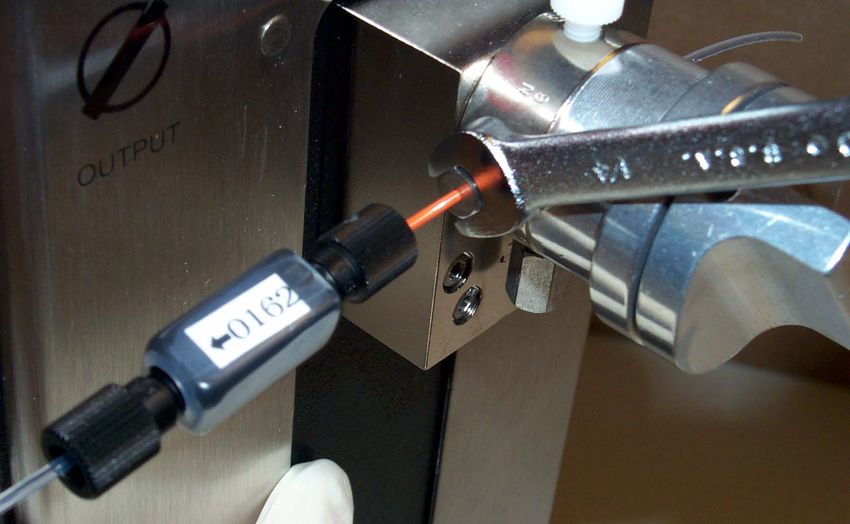
4.3 HARDWARE INSTALLATION
1. Plug the serial cable’s 25-pin DIO connector into
the DIO port, located at the lower left of the FIGURE 4-2 Power and Serial Connections
HydroShear DNA Shearing Device’s back panel.
(FIGURE 4-2)
2. Secure the DIO connection to the HydroShear
DNA Shearing Device by tightening the screws on Power
either side of the DIO connector. Switch
3. Plug the serial cable’s serial connector into a serial
port on the CPU. (FIGURE 4-2)
After installing the HydroShear DNA Shearing DIO Port AC Male
Device software, you will need to specify which serial Receptacle
port is used in the software’s Machine Parameters
Entry Window. (See 5.6.1.5 Port Number, page 43).
4. Plug the power cord’s AC connector end into the
AC male receptacle on the back of the HydroShear DNA Shearing Device. (FIGURE 4-2)
5. Plug the power cord’s three-prong end into a properly grounded wall outlet (110V / 15amp).
6. Turn the HydroShear DNA Shearing Device’s power switch into the On position.
The power switch is located on the back of the machine, at the lower right corner (as viewed from the back).
7. After installing the HydroShear DNA Shearing Device software (See 4.4 Software Installation, page 29),
open the software by locating the program titled “HydroShear DNA Shearing Device” in the Windows
Start ⇒ Programs menu.
4.4 SOFTWARE INSTALLATION
1. Insert the HydroShear DNA Shearing Device installation disk into the CPU’s floppy disk drive.
2. Run the file “setup.exe” from the installation disk.
On most PC’s, this can be accomplished by following these steps:
1. Select “Run. . . “ from the Start menu.
--A dialog box appears prompting you to specify the file to run.
2. Type “A:\Setup.EXE” in the text box.
3. Click “OK.”
--The Install software program opens.
--Follow the instructions displayed onscreen by the Install software.
HydroShear® DNA Shearing Device User Manual 294.5 SHEARING ASSEMBLY INSTALLATION
The shearing assembly must be oriented correctly, both to prevent irreversible damage to the orifice
and to function properly. Carefully read the instructions below and refer to Figure 4-3, “A Shearing
! Assembly,” on page 30 to ensure that you correctly install the shearing assembly.
4.5.1 Shearing Assembly Components
FIGURE 4-3 A Shearing Assembly
Dismantled Shearing Assembly
nut orifice base
ferrule box ferrule nut screw
metal
ferrule
3 6
2 4
1 7
5
Shearing Assembly
The components of the shearing assembly (FIGURE 4-3) must be correctly ordered and
oriented in order to function properly and prevent damage to the machine. Although the
shearing assembly is always correctly assembled at GeneMachines, you may use the
following guidelines to ensure that the components are correctly ordered and oriented
before attaching the assembly to the machine:
Starting at the clear plastic tubing and moving from left to right, the following components of the shearing assembly
should be visible (FIGURE 4-3):
1. Clear plastic tubing
This tube serves as the output tube. The sheared samples and used wash solution will be dispensed from this
tube. If this tube is detached from the shearing assembly (by unscrewing the tubing nut), you can see a plastic
ferrule attached to the end that is inserted into the shearing orifice. The ferrule is oriented so that the untapered
end is flush with the end of the tubing.
30
Work Less. Do More.™Installing the HydroShear DNA Shearing Device
2. Tubing nut
This nut screws into the orifice box at the head of the orifice box’s arrow label. It attaches the output tube to the
shearing assembly.
3. Orifice box
The orifice box of any shearing assembly shipped after March 2000 is labeled with an arrow and an identification
number. The arrow should always point towards the clear plastic output tubing. If the arrow is missing, you can
observe the inside of the orifice to determine the correct orientation. (See 4.5.2 Determining the Correct
Orientation of an Unlabeled Orifice Box, page 31)
The identification number is useful for keeping calibration records.
4. Tubing nut
This nut screws into the orifice box at the tail of the orifice box’s arrow label. It attaches the orifice box to the
PEEK tubing (the orange inflexible tubing) leading to the base screw.
5. Peek tubing
This orange, inflexible tubing is attached to the orifice box via the tubing nut (4) and is attached to the base unit
via the base screw (6).
6. Base screw
Called the “base screw” since it attaches the shearing assembly to the base unit, this screw is a 1/16" hex screw.
The threaded side of the base screw should be closest to the metal ferrule.
7. Metal ferrule
The tapered end of this ferrule should be closest to the end of the orange tubing.
4.5.2 Determining the Correct Orientation of an Unlabeled Orifice Box
If you have an orifice box without an arrow label, follow these steps to determine the correct orientation:
1. Remove all tubing from the orifice box and hold it near a light.
2. Look through the tubing nut ports to observe a pinkish circle of color; this is the ruby.
One side of the ruby will appear smaller and less reflective than the other.
3. Screw the output tube’s tubing nut into the port through which the ruby appears smaller and less
reflective.
4. Screw the tubing nut leading to the orange inflexible tubing and base screw into the port through which the
ruby appears larger and more reflective.
HydroShear® DNA Shearing Device User Manual 314.5.3 Attaching the Shearing Assembly to the HydroShear DNA
Shearing Device
1. Check to see that the
three components of the FIGURE 4-4 Attaching the Shearing Assembly to the Base Unit
shearing assembly are
correctly oriented. (See
4.5.1 Shearing Assembly
Components, page 30)
base screw
orifice
2. Twist the base screw
arrow
into the port on the left
side of the valve.
The left side of the valve
is the output side.
Because the shearing
assembly leads to the
output tube, the shearing
assembly’s base screw ferrule
port is located on this
left, output side.
3. Tighten the base screw
FIGURE 4-5 Tightening the Base Screw
connection with the
1/4" hex wrench.
4. Calibrate the shearing
assembly (if new or if
your calibration records
have been misplaced).
Each new shearing
assembly needs to be
individually calibrated.
(See 4.5.4 Calibrating
the Shearing Assembly,
page 33).
base screw
hex wrench
32
Work Less. Do More.™Installing the HydroShear DNA Shearing Device
4.5.4 Calibrating the Shearing Assembly
Each new shearing assembly needs to be individually calibrated. Since the size of each shearing assembly’s orifice is
slightly different, the same Speed Code, when used with different shearing assemblies, will not necessarily result in
the same fragment size. The typical variation in fragment size produced by different shearing assemblies is
approximately 500 bp. This calibration will determine the Speed Code to fragment size correlation for a specific
shearing assembly.
To calibrate a shearing assembly, follow these steps:
TABLE 1. Typical
Size to Speed
1. Shear several DNA samples at various Speed Code values, keeping
Code Correlation
the Volume, the Number of Cycles, and the DNA concentration
constant.
Average
Shearing at four different Speed Codes should be sufficient for most Fragment Size
users. To increase the precision of the calibration, shear at more Speed Speed Code (kb)
Codes. 3 1-2
9 1.5-3
2. Compare the resultant fragment sizes by gel electrophoresis,
15 5-10
keeping track of which Speed Codes produced which fragments.
3. Make a record of the average fragment size produced at each
Speed Code.
Use the identification number on the shearing assembly’s orifice box.
You can then reference this record when determining the Speed Code for future shearing runs.
HydroShear® DNA Shearing Device User Manual 3334
Work Less. Do More.™Software
5. Software
5.1 STARTING THE HYDROSHEAR DNA SHEARING
DEVICE SOFTWARE
1. To start the HydroShear DNA Shearing Device software, locate the program titled “HydroShear DNA
Shearing Device” in the Windows Start ⇒Programs menu.
The HydroShear DNA Shearing Device Main Panel appears, and the pump is initialized.
A dialog box appears displaying the following message: “Machine parameters are currently set to the factory
defaults. If you don’t wish to use factory settings, you should specify other values for the machine before
continuing.”
2. Click “OK.”
The dialog box disappears.
Continue by resetting machine parameters (See 8. Machine Parameters, page 51), setting shearing parameters
(See 5.3 Shearing Parameters, page 37), or shearing (See 6. Shearing, page 45).
HydroShear® DNA Shearing Device User Manual 35FIGURE 5-1 HydroShear DNA Shearing Device Main Panel
5.2 A TOUR OF THE HYDROSHEAR DNA SHEARING
DEVICE MAIN PANEL
The HydroShear DNA Shearing Device Main Panel is the HydroShear DNA Shearing Device’s control and feedback
center. The HydroShear DNA Shearing Device Main Panel is divided into three boxed areas titled “Shearing
Parameters,” “Operation Controls,” and “Status.”
Shearing Parameters
You will use this box to customize shearing parameters for the upcoming shearing run, save customized shearing
parameters to a file, instruct the software to use parameters saved to a file, or set new default parameter values.
For detailed explanations and instructions, see 5.3 Shearing Parameters, page 37.
36
Work Less. Do More.™Software
Operation Controls
This box includes the buttons used to run the HydroShear DNA Shearing Device and a button used to navigate to
the Manual Operation window. (See 7. Manual Operation, page 53)
For detailed explanations of the Operation Controls and instructions for use, see 5.4 Operation Controls, page
40.
Status
This box displays the status of a current shearing run or wash, as well as the current pump volume.
For detailed explanations and instructions, see 5.5 Status, page 41.
5.3 SHEARING PARAMETERS
The shearing parameters, including the basic shearing parameters and the wash scheme, can be edited using the
Shearing Parameters box, located on the left side of the HydroShear DNA Shearing Device Main Panel.
5.3.1 Basic Shearing Parameters Defined
Three basic shearing parameters are referenced by the HydroShear DNA Shearing Device software: Volume, Number
of Cycles, and Speed Code. The default value for each is displayed upon starting the software. However, these values
can be adjusted for each run (See 5.3.2 Editing Basic Shearing Parameter Values, page 38), or new defaults can be
defined (See 5.3.5 Saving New Shearing Parameter Default Values, page 39):
5.3.1.1 Volume
This is the volume of the sample, in microliters (µL) you are preparing to shear. This value can range from the
Void Volume to the “Syringe Volume,” both of which are specified in the Machine Parameters window. (See 8.1
The Machine Parameters defined, page 51). However, GeneMachines’ biologists have found that shearing will
be incomplete unless the Volume is at least 40 µL. (See 3.3.2 Smallest Sample Volume that Can Be Sheared, page
19).
If your sample volume is greater than 300 µL, you will need to use the longer output
! tube included with your HydroShear DNA Shearing Device.
5.3.1.2 Number of Cycles
This number refers to the number of shearing passes you want the machine to perform on the sample. A typical
Number of Cycles is 20; after the twentieth cycle, additional shearing passes are unlikely to shear the sample any
further.
HydroShear® DNA Shearing Device User Manual 375.3.1.3 Speed Code
The Speed Code correlates with the speed of the pump when performing the shearing passes. The optimal value
depends on both the individual orifice size of the shearing assembly (there are slight variations in size among
orifices) and the fragment size desired.
The Speed Code can range from 0 to 40, with an increasing Speed Code value corresponding with a decreased
pump plunger speed. A Speed Code of 0 results in the fastest speed (1.2 seconds per stroke), while a Speed Code
of 40 results in the slowest speed (600 seconds per stroke).
Note that, if the Speed Code entered is less than 20, the software will automatically insert three “pre-passes” into
the shearing run. These pre-passes will occur before the actual shearing cycles and are executed at gradually
higher speeds to prepare for the high-speed shearing passes.
Standard-size shearing assemblies normally should not be operated at a Speed
! Code lower than 3; standard-sized shearing assemblies cannot perform at the
lowest Speed Codes (0,1, and 2) and will produce a pump overload message.
Remember! The lower the Speed Code, the faster the speed!
5.3.2 Editing Basic Shearing Parameter Values
To edit a parameter value, follow these steps:
1. Locate the text box next to the parameter name (e.g. “Volume”).
2. Either click in the text box and type in the desired value, or click the arrows next to the text box to display
the desired value.
NOTE: Should you edit basic shearing parameter values and/or wash scheme values and wish to restore the default
values, simply click the RESTORE TO DEFAULTS button, located at the bottom left corner of the Shearing
Parameters box on the HydroShear DNA Shearing Device Main Panel. Upon clicking this button, the last set of basic
parameter values that were saved as default values will be displayed in the text boxes. Remember that this will restore
both the default basic shearing parameter values and the default wash scheme values!
5.3.3 The Wash Scheme
The wash scheme should be conducted before and after each shearing run to clean any residual sample solution from
the machine. The wash scheme is defined in, and can be edited in, the Edit Wash Scheme window.
To reach the Edit Wash Scheme window, click the EDIT WASH SCHEME button on the HydroShear DNA Shearing
Device Main Panel.
38
Work Less. Do More.™Software
To define a wash scheme, follow these steps:
Typical Wash Scheme
1. Click in the top text box in the column headed “Solution.”
A typical wash scheme consists
2. Type a name for the first wash solution. of:
1. HCl -- 4 cycles
3. In the first text box underneath the heading “Cycles,” specify the
number of wash cycles that should be completed using the first wash 2. NaOH -- 4 cycles
solution. To do so, either click in the text box and type a number, or click 3. Water/Buffer -- 4 cycles
the arrows next to the text box to change the displayed number.
4. Repeat Steps 1-3, using the second text box in each column for the second wash solution and the third for
the third wash solution.
5. Click the OK button, located at the bottom of the Edit Wash Scheme window.
The Edit Wash Scheme window disappears. The HydroShear DNA Shearing Device Main Panel Appears.
5.3.4 Saving Shearing Parameters Values to a File
Custom shearing parameter values can be saved to a file, allowing for easy recall and entry when conducting future
shearing runs. This file is user-named and will be stored in the user-specified location.
To save shearing parameter values to a file, follow these steps:
1. After entering values for each basic shearing parameter (See 5.3.2 Editing Basic Shearing Parameter Values,
page 38) and for the wash scheme (See 5.3.3 The Wash Scheme, page 38), click the SAVE TO FILE button.
The “Choose file to write. . . “ dialog box appears.
2. Navigate to the location where you would like to save the file.
3. Type a name for the file in the text box.
4. Click the SAVE button.
The new shearing parameters values are saved with the specified name in the specified location.
5.3.5 Saving New Shearing Parameter Default Values
1. After entering values for each basic shearing parameter and for the wash scheme (See 5.3.2 Editing Basic
Shearing Parameter Values, page 38 and 5.3.3 The Wash Scheme, page 38), click the SAVE AS DEFAULT
button.
The new values are saved and are used as the default values for every shearing run.
HydroShear® DNA Shearing Device User Manual 39Remember that the shearing parameter default values include default wash scheme
! values; clicking the SAVE AS DEFAULT button will save both the currently
entered basic parameter values and the currently entered wash scheme values as the
new default values!
5.3.6 Restoring Shearing Parameter Default Values
Should you edit the shearing parameter values (i.e. the basic shearing parameter values and/or wash scheme values)
and wish to restore the default values:
1. Click the RESTORE TO DEFAULTS button, located at the bottom left corner of the Shearing Parameters
box on the HydroShear DNA Shearing Device Main Panel.
The most recently saved default values are displayed in the text boxes.
Note that this will restore both the default basic shearing parameter values and the
default wash scheme values!
5.4 OPERATION CONTROLS
Four buttons are located in the Operation Controls box on the HydroShear DNA Shearing Device Main Panel:
Click the START button to start a shearing run. (See 6. Shearing, page 45).
Click the STOP button to stop a shearing run already in progress. The machine will stop after the
current pump pass is complete.
Click the PAUSE button to pause the current shearing run. (The machine will complete its current
shearing pass and then pause). While paused, click this button again to resume the shearing run. Take
care not to repeatedly click this button to “speed up” the software and/or machine’s response; each click
is registered and acted upon. Thus, repeated clicking will start a cycle of pause/unpause/pause/unpause
and so on.
Click the MANUAL OPERATION button to display the Manual Operation window,
where you can conduct individual shearing steps. (See 7. Manual Operation, page
53).
40
Work Less. Do More.™Software
5.5 STATUS
The Status box displays three status items -- Current Step, Wash Status, and Current Pump Volume -- and can be
particularly useful when diagnosing and resolving troubleshooting issues. (See 9. Troubleshooting, page 67). The
status items are described below:
Current Step
This box displays a list of each step of the current shearing run. When a shearing run is in progress, the current
step is highlighted.
Progress
The white box in the top right corner of the Status box displays the progress of the current step (highlighted in the
Current Step box). Progress is displayed in the following format: of .
Note that, when viewing the progress of a Wash step, the total number of wash cycles is the total of all wash
cycles specified to occur with each of the three wash solutions. For example, if you specified in your wash
scheme that you would like to conduct four wash cycles with each of the three wash solutions, the total number
of wash cycles is twelve. (See 5.3.3 The Wash Scheme, page 38).
Current Pump Volume
This box displays the volume of liquid (in µL) currently in the syringe.
5.6 MACHINE PARAMETERS
Several machine parameters that are determined and set at GeneMachines can be adjusted in the Machine
Parameters window. New default values can be specified, or the saved default values or factory-set values can
be restored. It is extremely unlikely that these parameter values will require user adjustment.
To open the Machine Parameters window, click the EDIT MACHINE PARAMETERS button on the HydroShear
DNA Shearing Device Main Panel.
HydroShear® DNA Shearing Device User Manual 41You can also read