EL-FLOW Select series Thermal Mass Flow Meters and Controllers - Bronkhorst
←
→
Page content transcription
If your browser does not render page correctly, please read the page content below
Instruction Manual

              EL-FLOW® Select series
     Thermal Mass Flow Meters and Controllers

                        Doc. no.: 9.17.099 rev. H   Date: 23-09-2020

                                         ATTENTION
       Please read this document carefully before installing and operating the product.
Not following the guidelines could result in personal injury and/or damage to the equipment.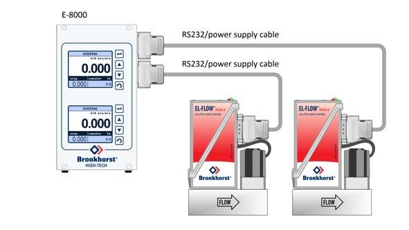
Bronkhorst®

Copyright
© 2020 Bronkhorst High-Tech B.V.
All rights reserved. No part of this publication may be reproduced, distributed, or transmitted in any form or by any means,
without the prior written permission of the publisher.

Disclaimer
This document has been reviewed and is believed to be accurate. Bronkhorst High-Tech B.V. does not assume liability for
errors, inaccuracies or absence of information. The material in this document merely serves information and illustration
purposes; no rights can be derived from its contents.

Bronkhorst High-Tech B.V. reserves the right to modify or improve its products and documentation without informing
anyone. As such, the information contained in this document is subject to change without notice. Device specifications and
the contents of the package may deviate from what is stated in this document.

Symbols in this document
             Important information. Disregarding this information could increase the risk of damage to the equipment, or the risk of
             personal injuries.

             Helpful information. This information will facilitate the use of the instrument and/or contribute to its optimal
             performance.

             Additional information available on the internet or from your Bronkhorst representative.

Receipt of equipment
Check the outside packaging box for damage incurred during shipment. If the box is damaged, the local carrier must be
notified at once regarding his liability, if so required. At the same time a report should be submitted to your Bronkhorst
representative.

Carefully remove the equipment from the box. Verify that the contents of the package was not damaged during shipment.
Should the equipment be damaged, the local carrier must be notified at once regarding his liability, if so required. At the
same time a report should be submitted to your Bronkhorst representative.

             · Check the packing list to ensure that you received all of the items included in the scope of delivery
             · Do not discard spare or replacement parts with the packaging material

Refer to Removal and return instructions about return shipment procedures.

Equipment storage
· The equipment should be stored in its original package in a climate controlled storage location.
· Care should be taken not to subject the equipment to excessive temperatures or humidity.
· See technical specifications for information about required storage conditions.

2                                               Instruction Manual EL-FLOW® Select                                              9.17.099H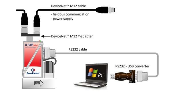
Bronkhorst®

Warranty
Bronkhorst® products are warranted against defects in material and workmanship for a period of three years from the date
of shipment, provided they are used in accordance with the ordering specifications and not subject to abuse or physical
damage. Products that do not operate properly during this period may be repaired or replaced at no charge. Repairs are
normally warranted for one year or the balance of the original warranty, whichever is the longer.

              See also section 9 (Guarantee) of the Conditions of sales:
              www.bronkhorst.com/int/about/conditions-of-sales/

The warranty includes all initial and latent defects, random failures, and indeterminable internal causes. It excludes failures
and damage caused by the customer, such as contamination, improper electrical hook-up, physical shock etc.

Re-conditioning of products primarily returned for warranty service that is partly or wholly judged non-warranty may be
charged for.

Bronkhorst High-Tech B.V. or affiliated company prepays outgoing freight charges when any part of the service is
performed under warranty, unless otherwise agreed upon beforehand. The costs of unstamped returns are added to the
repair invoice. Import and/or export charges as well as costs of foreign shipping methods and/or carriers are paid by the
customer.

General safety precautions
This product is intended for use by qualified personnel who recognize shock hazards and are familiar with the safety
precautions required to avoid possible injury. Read the operating information carefully before using the product.

Before operating, make sure the line cord is connected to a properly grounded power receptacle. Inspect the connecting
cables for cracks or breaks before each use.

The equipment and accessories must be used in accordance with their specifications and operating instructions, otherwise
the safety of the equipment may be impaired.

Opening the equipment is not allowed. There are no user serviceable parts inside. In case of a defect please return the
equipment to Bronkhorst High-Tech B.V.

One or more warning signs may be attached to the product. These signs have the following meaning:

              General warning; consult the instruction manual for handling instructions

              Surface may get hot during operation

              Shock hazard; electrical parts inside

To maintain protection from electric shock and fire, replacement components must be obtained from Bronkhorst. Standard
fuses, with applicable national safety approvals, may be used if the rating and type are the same. Other components that are
not safety related may be obtained from other suppliers, as long as they are equivalent to the original component. Selected
parts should be obtained only through Bronkhorst, to maintain accuracy and functionality of the product. If you are unsure
about the relevance of a replacement component, contact your Bronkhorst representative for information.

9.17.099H                                       Instruction Manual EL-FLOW® Select                                                3
Bronkhorst®

4   Instruction Manual EL-FLOW® Select   9.17.099H
Bronkhorst®

Table of contents

1                 ............................................................................................................7
          Introduction
1.1       Scope of this
                    . . . . manual
                            ........................................................................................................7
1.2       Intended use
                   ............................................................................................................7
1.3       Product description
                   ............................................................................................................7
1.4       Calibration. . . . . . . . . . . . . . . . . . . . . . . . . . . . . . . . . . . . . . . . . . . . . . . . . . . . . . . . . . . . . . . . . . . . . . . . . . . . . . . . . . . . . . . . . . . . . . . . . . . . . . . . . . . . 8
1.5       Maintenance
                  ............................................................................................................8
1.6       Documentation
                  ............................................................................................................9
1.7       Model key. . . . . . . . . . . . . . . . . . . . . . . . . . . . . . . . . . . . . . . . . . . . . . . . . . . . . . . . . . . . . . . . . . . . . . . . . . . . . . . . . . . . . . . . . . . . . . . . . . . . . . . . . . . . 9
1.7.1     EL-FLOW®. . Select
                      . . . . . . . . . . . . . . . . . . . . . . . . . . . . . . . . . . . . . . . . . . . . . . . . . . . . . . . . . . . . . . . . . . . . . . . . . . . . . . . . . . . . . . . . . . . . . . . . . . . . . . . . . . 10
1.7.2     EL-FLOW®. . Metal
                      . . . . . . Sealed
                                  . . . . . . . . . . . . . . . . . . . . . . . . . . . . . . . . . . . . . . . . . . . . . . . . . . . . . . . . . . . . . . . . . . . . . . . . . . . . . . . . . . . . . . . . . . . . . . . . . . . . 11
1.8       Sealing material
                   . . . . . . . . compatibility
                                   . . . . . . . . . . . . . . . . . . . . . . . . . . . . . . . . . . . . . . . . . . . . . . . . . . . . . . . . . . . . . . . . . . . . . . . . . . . . . . . . . . . . . . . . . . . . . . . . . . . . 12
2                 . . . . . . . . . . . . . . . . . . . . . . . . . . . . . . . . . . . . . . . . . . . . . . . . . . . . . . . . . . . . . . . . . . . . . . . . . . . . . . . . . . . . . . . . . . . . . . . . . . . . . . . . . . . . 13
          Installation
2.1       Functional
                  . . .properties
                       . . . . . . . . . . . . . . . . . . . . . . . . . . . . . . . . . . . . . . . . . . . . . . . . . . . . . . . . . . . . . . . . . . . . . . . . . . . . . . . . . . . . . . . . . . . . . . . . . . . . . . . . . 13
2.2       Operating. . conditions
                       . . . . . . . . . . . . . . . . . . . . . . . . . . . . . . . . . . . . . . . . . . . . . . . . . . . . . . . . . . . . . . . . . . . . . . . . . . . . . . . . . . . . . . . . . . . . . . . . . . . . . . . . . . 13
2.3       Mounting. . . . . . . . . . . . . . . . . . . . . . . . . . . . . . . . . . . . . . . . . . . . . . . . . . . . . . . . . . . . . . . . . . . . . . . . . . . . . . . . . . . . . . . . . . . . . . . . . . . . . . . . . . . . 13
2.4       Piping requirements
                   . . . . . . . . . . . . . . . . . . . . . . . . . . . . . . . . . . . . . . . . . . . . . . . . . . . . . . . . . . . . . . . . . . . . . . . . . . . . . . . . . . . . . . . . . . . . . . . . . . . . . . . . . . . . 13
2.5       Fluid connection
                   . . . . . . . . . . . . . . . . . . . . . . . . . . . . . . . . . . . . . . . . . . . . . . . . . . . . . . . . . . . . . . . . . . . . . . . . . . . . . . . . . . . . . . . . . . . . . . . . . . . . . . . . . . . . 14
2.6       Electrical .connection
                       . . . . . . . . . . . . . . . . . . . . . . . . . . . . . . . . . . . . . . . . . . . . . . . . . . . . . . . . . . . . . . . . . . . . . . . . . . . . . . . . . . . . . . . . . . . . . . . . . . . . . . . . . . . 14
2.7       Fieldbus .connection
                     . . . . . . . . . . . . . . . . . . . . . . . . . . . . . . . . . . . . . . . . . . . . . . . . . . . . . . . . . . . . . . . . . . . . . . . . . . . . . . . . . . . . . . . . . . . . . . . . . . . . . . . . . . . 14
2.7.1     FLOW-BUS
                 . . . . . . . . . . . . . . . . . . . . . . . . . . . . . . . . . . . . . . . . . . . . . . . . . . . . . . . . . . . . . . . . . . . . . . . . . . . . . . . . . . . . . . . . . . . . . . . . . . . . . . . . . . . . 15
2.7.2     Modbus . . . . . . . . . . . . . . . . . . . . . . . . . . . . . . . . . . . . . . . . . . . . . . . . . . . . . . . . . . . . . . . . . . . . . . . . . . . . . . . . . . . . . . . . . . . . . . . . . . . . . . . . . . . . 15
2.7.3     PROFIBUS. .DP
                     . . . . . . . . . . . . . . . . . . . . . . . . . . . . . . . . . . . . . . . . . . . . . . . . . . . . . . . . . . . . . . . . . . . . . . . . . . . . . . . . . . . . . . . . . . . . . . . . . . . . . . . . . . 15
2.7.4     DeviceNet™
                  . . . . . . . . . . . . . . . . . . . . . . . . . . . . . . . . . . . . . . . . . . . . . . . . . . . . . . . . . . . . . . . . . . . . . . . . . . . . . . . . . . . . . . . . . . . . . . . . . . . . . . . . . . . . 15
2.7.5     EtherCAT®
                  . . . . . . . . . . . . . . . . . . . . . . . . . . . . . . . . . . . . . . . . . . . . . . . . . . . . . . . . . . . . . . . . . . . . . . . . . . . . . . . . . . . . . . . . . . . . . . . . . . . . . . . . . . . . 15
2.7.6     PROFINET. . . . . . . . . . . . . . . . . . . . . . . . . . . . . . . . . . . . . . . . . . . . . . . . . . . . . . . . . . . . . . . . . . . . . . . . . . . . . . . . . . . . . . . . . . . . . . . . . . . . . . . . . . . . 15
2.8       Communication
                . . . . . . . . interface
                                . . . . . . . . . . . . . . . . . . . . . . . . . . . . . . . . . . . . . . . . . . . . . . . . . . . . . . . . . . . . . . . . . . . . . . . . . . . . . . . . . . . . . . . . . . . . . . . . . . . . 16
2.8.1     RS232 communication
                  . . . . . . . . . . . . . . . . . . . . . . . . . . . . . . . . . . . . . . . . . . . . . . . . . . . . . . . . . . . . . . . . . . . . . . . . . . . . . . . . . . . . . . . . . . . . . . . . . . . . . . . . . . . . 17
2.8.2     Fieldbus .communication
                     . . . . . . . . . . . . . . . . . . . . . . . . . . . . . . . . . . . . . . . . . . . . . . . . . . . . . . . . . . . . . . . . . . . . . . . . . . . . . . . . . . . . . . . . . . . . . . . . . . . . . . . . . . . 17
2.8.3     E-8000 power
                  . . . . . .supply,
                              . . . . . . . .readout
                                              . . . . . . . . .and
                                                                . . . . control
                                                                        . . . . . . . . . . . . . . . . . . . . . . . . . . . . . . . . . . . . . . . . . . . . . . . . . . . . . . . . . . . . . . . . . . . . . . . . . . . . . . . . . 18
2.8.4     BRIGHT readout
                  . . . . . . . . and
                                  . . . . .control
                                            . . . . . . . . . . . . . . . . . . . . . . . . . . . . . . . . . . . . . . . . . . . . . . . . . . . . . . . . . . . . . . . . . . . . . . . . . . . . . . . . . . . . . . . . . . . . . . . 18
3                . . . . . . . . . . . . . . . . . . . . . . . . . . . . . . . . . . . . . . . . . . . . . . . . . . . . . . . . . . . . . . . . . . . . . . . . . . . . . . . . . . . . . . . . . . . . . . . . . . . . . . . . . . . . 19
          Operation
3.1       Powering. .up
                      . . . and
                            . . . . .powering
                                      . . . . . . . . . . down
                                                          . . . . . . . . . . . . . . . . . . . . . . . . . . . . . . . . . . . . . . . . . . . . . . . . . . . . . . . . . . . . . . . . . . . . . . . . . . . . . . . . . . . . . . . . 19
3.2       First use . . . . . . . . . . . . . . . . . . . . . . . . . . . . . . . . . . . . . . . . . . . . . . . . . . . . . . . . . . . . . . . . . . . . . . . . . . . . . . . . . . . . . . . . . . . . . . . . . . . . . . . . . . . . 19
3.3       Mass flow. . measurement
                       . . . . . . . . . . . . . . . and
                                                     . . . . .control
                                                               . . . . . . . . . . . . . . . . . . . . . . . . . . . . . . . . . . . . . . . . . . . . . . . . . . . . . . . . . . . . . . . . . . . . . . . . . . . . . . . . . . . . . . 19
3.3.1     Changing. . fluid
                       . . . . . set
                                 . . . . . . . . . . . . . . . . . . . . . . . . . . . . . . . . . . . . . . . . . . . . . . . . . . . . . . . . . . . . . . . . . . . . . . . . . . . . . . . . . . . . . . . . . . . . . . . . . . . . . 20
3.4       Valve Safe
                   . . State
                       . . . . . . . . . . . . . . . . . . . . . . . . . . . . . . . . . . . . . . . . . . . . . . . . . . . . . . . . . . . . . . . . . . . . . . . . . . . . . . . . . . . . . . . . . . . . . . . . . . . . . . . . . . 21
3.5       Manual controls
                  . . . . . . . . . . . . . . . . . . . . . . . . . . . . . . . . . . . . . . . . . . . . . . . . . . . . . . . . . . . . . . . . . . . . . . . . . . . . . . . . . . . . . . . . . . . . . . . . . . . . . . . . . . . . 21
3.5.1     LED indications
                   . . . . . . . . . . . . . . . . . . . . . . . . . . . . . . . . . . . . . . . . . . . . . . . . . . . . . . . . . . . . . . . . . . . . . . . . . . . . . . . . . . . . . . . . . . . . . . . . . . . . . . . . . . . . 21
3.5.1.1   Interface .status
                      . . . . . . . . . . . . . . . . . . . . . . . . . . . . . . . . . . . . . . . . . . . . . . . . . . . . . . . . . . . . . . . . . . . . . . . . . . . . . . . . . . . . . . . . . . . . . . . . . . . . . . . . . . . 23
3.5.1.2   DeviceNet™
                  . . . .indications
                          . . . . . . . . . . . . . . . . . . . . . . . . . . . . . . . . . . . . . . . . . . . . . . . . . . . . . . . . . . . . . . . . . . . . . . . . . . . . . . . . . . . . . . . . . . . . . . . . . . . . . . . . 23
3.5.2     Multifunctional
                  . . . . . . . .switch
                                  . . . . . . . . . . . . . . . . . . . . . . . . . . . . . . . . . . . . . . . . . . . . . . . . . . . . . . . . . . . . . . . . . . . . . . . . . . . . . . . . . . . . . . . . . . . . . . . . . . . . 24
3.5.2.1   Normal operating
                  . . . . . . . . . . functions
                                      . . . . . . . . . . . . . . . . . . . . . . . . . . . . . . . . . . . . . . . . . . . . . . . . . . . . . . . . . . . . . . . . . . . . . . . . . . . . . . . . . . . . . . . . . . . . . . . . . . 24
3.5.2.2   Power-up. .functions
                      . . . . . . . . . . . . . . . . . . . . . . . . . . . . . . . . . . . . . . . . . . . . . . . . . . . . . . . . . . . . . . . . . . . . . . . . . . . . . . . . . . . . . . . . . . . . . . . . . . . . . . . . . . 25
3.5.2.3   Control mode
                  . . . . . . -. .readout/change
                                   . . . . . . . . . . . . . . . . . . . . . . . . . . . . . . . . . . . . . . . . . . . . . . . . . . . . . . . . . . . . . . . . . . . . . . . . . . . . . . . . . . . . . . . . . . . . . . . . . . . . 25
3.5.2.4   Network .settings
                    . . . . . . . . -. .readout/change
                                         . . . . . . . . . . . . . . . . . . . . . . . . . . . . . . . . . . . . . . . . . . . . . . . . . . . . . . . . . . . . . . . . . . . . . . . . . . . . . . . . . . . . . . . . . . . . . . . . . 26
3.5.3     Rotary switches
                   . . . . . . . . . . . . . . . . . . . . . . . . . . . . . . . . . . . . . . . . . . . . . . . . . . . . . . . . . . . . . . . . . . . . . . . . . . . . . . . . . . . . . . . . . . . . . . . . . . . . . . . . . . . . 27

9.17.099H                                                                       Instruction Manual EL-FLOW® Select                                                                                                                           5
Bronkhorst®

3.6                  . . . . . . . . . . . . . . . . . . . . . . . . . . . . . . . . . . . . . . . . . . . . . . . . . . . . . . . . . . . . . . . . . . . . . . . . . . . . . . . . . . . . . . . . . . . . . . . . . . . . . . . . . . . . 28
               Communication
3.6.1          Analog operation
                       . . . . . . . . . . . . . . . . . . . . . . . . . . . . . . . . . . . . . . . . . . . . . . . . . . . . . . . . . . . . . . . . . . . . . . . . . . . . . . . . . . . . . . . . . . . . . . . . . . . . . . . . . . . . 28
3.6.2          Digital operation
                        . . . . . . . . . (RS232)
                                          . . . . . . . . . . . . . . . . . . . . . . . . . . . . . . . . . . . . . . . . . . . . . . . . . . . . . . . . . . . . . . . . . . . . . . . . . . . . . . . . . . . . . . . . . . . . . . . . . . . 29
3.6.2.1        FlowDDE. . . . . . . . . . . . . . . . . . . . . . . . . . . . . . . . . . . . . . . . . . . . . . . . . . . . . . . . . . . . . . . . . . . . . . . . . . . . . . . . . . . . . . . . . . . . . . . . . . . . . . . . . . . . 29
3.6.2.2        Software. (DDE
                          . . . . . .applications)
                                      . . . . . . . . . . . . . . . . . . . . . . . . . . . . . . . . . . . . . . . . . . . . . . . . . . . . . . . . . . . . . . . . . . . . . . . . . . . . . . . . . . . . . . . . . . . . . . . . . . . . . 30
3.6.3          Digital fieldbus
                         . . . . . . . .operation
                                         . . . . . . . . . . (RS485)
                                                             . . . . . . . . . . . . . . . . . . . . . . . . . . . . . . . . . . . . . . . . . . . . . . . . . . . . . . . . . . . . . . . . . . . . . . . . . . . . . . . . . . . . . . . . . . 30
3.7            Adjusting. .zero
                            . . . . .point
                                     . . . . . . . . . . . . . . . . . . . . . . . . . . . . . . . . . . . . . . . . . . . . . . . . . . . . . . . . . . . . . . . . . . . . . . . . . . . . . . . . . . . . . . . . . . . . . . . . . . . . . 32
3.7.1          Using multifunctional
                      . . . . . . . . . . . . . . switch
                                                  . . . . . . . . . . . . . . . . . . . . . . . . . . . . . . . . . . . . . . . . . . . . . . . . . . . . . . . . . . . . . . . . . . . . . . . . . . . . . . . . . . . . . . . . . . . . . . 32
3.7.2          Via digital. . communication
                              . . . . . . . . . . . . . . . . . . . . . . . . . . . . . . . . . . . . . . . . . . . . . . . . . . . . . . . . . . . . . . . . . . . . . . . . . . . . . . . . . . . . . . . . . . . . . . . . . . . . . . . . . . 32
4                      . . . . . . . . . . . . . . . . . . . . . . . . . . . . . . . . . . . . . . . . . . . . . . . . . . . . . . . . . . . . . . . . . . . . . . . . . . . . . . . . . . . . . . . . . . . . . . . . . . . . . . . . . . . . 33
               Digital parameters
4.1            General . . . . . . . . . . . . . . . . . . . . . . . . . . . . . . . . . . . . . . . . . . . . . . . . . . . . . . . . . . . . . . . . . . . . . . . . . . . . . . . . . . . . . . . . . . . . . . . . . . . . . . . . . . . . 33
4.2            Special parameters
                        . . . . . . . . . . . . . . . . . . . . . . . . . . . . . . . . . . . . . . . . . . . . . . . . . . . . . . . . . . . . . . . . . . . . . . . . . . . . . . . . . . . . . . . . . . . . . . . . . . . . . . . . . . . . 34
4.2.1          Default control
                        . . . . . . . mode
                                      . . . . . . . . . . . . . . . . . . . . . . . . . . . . . . . . . . . . . . . . . . . . . . . . . . . . . . . . . . . . . . . . . . . . . . . . . . . . . . . . . . . . . . . . . . . . . . . . . . . . . 35
4.3            Measurement
                      . . . . . . and
                                  . . . . .control
                                            . . . . . . . . . . . . . . . . . . . . . . . . . . . . . . . . . . . . . . . . . . . . . . . . . . . . . . . . . . . . . . . . . . . . . . . . . . . . . . . . . . . . . . . . . . . . . . . . . 35
4.3.1          Advanced. . measurement
                           . . . . . . . . . . . . . . .and
                                                         . . . . control
                                                                 . . . . . . . . . . . . . . . . . . . . . . . . . . . . . . . . . . . . . . . . . . . . . . . . . . . . . . . . . . . . . . . . . . . . . . . . . . . . . . . . . . . . . . . 36
4.4            Device identification
                        . . . . . . . . . . . . . . . . . . . . . . . . . . . . . . . . . . . . . . . . . . . . . . . . . . . . . . . . . . . . . . . . . . . . . . . . . . . . . . . . . . . . . . . . . . . . . . . . . . . . . . . . . . . . 37
4.5            Alarms . . . . . . . . . . . . . . . . . . . . . . . . . . . . . . . . . . . . . . . . . . . . . . . . . . . . . . . . . . . . . . . . . . . . . . . . . . . . . . . . . . . . . . . . . . . . . . . . . . . . . . . . . . . . 38
4.6            Counter . . . . . . . . . . . . . . . . . . . . . . . . . . . . . . . . . . . . . . . . . . . . . . . . . . . . . . . . . . . . . . . . . . . . . . . . . . . . . . . . . . . . . . . . . . . . . . . . . . . . . . . . . . . . 40
4.7            Network .configuration
                         . . . . . . . . . . . . . . . . . . . . . . . . . . . . . . . . . . . . . . . . . . . . . . . . . . . . . . . . . . . . . . . . . . . . . . . . . . . . . . . . . . . . . . . . . . . . . . . . . . . . . . . . . . . 41
4.8            Fluid set . . . . . . . . . . . . . . . . . . . . . . . . . . . . . . . . . . . . . . . . . . . . . . . . . . . . . . . . . . . . . . . . . . . . . . . . . . . . . . . . . . . . . . . . . . . . . . . . . . . . . . . . . . . . 42
4.8.1          Advanced. . fluid
                            . . . . . set
                                      . . . . parameters
                                              . . . . . . . . . . . . . . . . . . . . . . . . . . . . . . . . . . . . . . . . . . . . . . . . . . . . . . . . . . . . . . . . . . . . . . . . . . . . . . . . . . . . . . . . . . . . . . . . . 44
4.9            Master/slave
                        . . . . .configuration
                                  . . . . . . . . . . . . . . .(FLOW-BUS)
                                                                . . . . . . . . . . . . . . . . . . . . . . . . . . . . . . . . . . . . . . . . . . . . . . . . . . . . . . . . . . . . . . . . . . . . . . . . . . . . . . . . . . . . . . . . 45
5                     . . . . . . . . . . . . .and
               Troubleshooting                  . . . . .service
                                                          . . . . . . . . . . . . . . . . . . . . . . . . . . . . . . . . . . . . . . . . . . . . . . . . . . . . . . . . . . . . . . . . . . . . . . . . . . . . . . . . . . . . . . . . . . 46
5.1            Errors and
                        . . warnings
                            . . . . . . . . . . . . . . . . . . . . . . . . . . . . . . . . . . . . . . . . . . . . . . . . . . . . . . . . . . . . . . . . . . . . . . . . . . . . . . . . . . . . . . . . . . . . . . . . . . . . . . . . . . 46
5.2            Restoring. .factory
                            . . . . . . . settings
                                          . . . . . . . . . . . . . . . . . . . . . . . . . . . . . . . . . . . . . . . . . . . . . . . . . . . . . . . . . . . . . . . . . . . . . . . . . . . . . . . . . . . . . . . . . . . . . . . . . . . 46
5.3            Common. issues
                       . . . . . . . . . . . . . . . . . . . . . . . . . . . . . . . . . . . . . . . . . . . . . . . . . . . . . . . . . . . . . . . . . . . . . . . . . . . . . . . . . . . . . . . . . . . . . . . . . . . . . . . . . . . 47
5.4            Service . . . . . . . . . . . . . . . . . . . . . . . . . . . . . . . . . . . . . . . . . . . . . . . . . . . . . . . . . . . . . . . . . . . . . . . . . . . . . . . . . . . . . . . . . . . . . . . . . . . . . . . . . . . . 49
6              Returns. . . . . . . . . . . . . . . . . . . . . . . . . . . . . . . . . . . . . . . . . . . . . . . . . . . . . . . . . . . . . . . . . . . . . . . . . . . . . . . . . . . . . . . . . . . . . . . . . . . . . . . . . . . . 50
6.1            Removal .and
                         . . . . return
                                 . . . . . . . instructions
                                               . . . . . . . . . . . . . . . . . . . . . . . . . . . . . . . . . . . . . . . . . . . . . . . . . . . . . . . . . . . . . . . . . . . . . . . . . . . . . . . . . . . . . . . . . . . . . . . . 50
6.2            Disposal .(end
                          . . . . .of
                                   . . .lifetime)
                                         . . . . . . . . . . . . . . . . . . . . . . . . . . . . . . . . . . . . . . . . . . . . . . . . . . . . . . . . . . . . . . . . . . . . . . . . . . . . . . . . . . . . . . . . . . . . . . . . . . . 50

             . . . . . . . . . . . . . . . . . . . . . . . . . . . . . . . . . . . . . . . . . . . . . . . . . . . . . . . . . . . . . . . . . . . . . . . . . . . . . . . . . . . . . . . . . . . . . . . . . . . . . . . . . . . . 51
Parameter index

6                                                                                    Instruction Manual EL-FLOW® Select                                                                                                          9.17.099H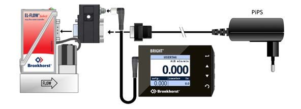
Bronkhorst®

1           Introduction
1.1         Scope of this manual
This manual covers the EL-FLOW® Select (including the EL-FLOW® Metal Sealed) series mass flow meters/controllers for
gases. It contains general product information, installation and operating instructions and troubleshooting tips.

                            Standard                                                              Metal sealed

1.2         Intended use
The EL-FLOW® Select is designed to accurately measure and/or control gas flow rates in a fluid system using the media and
operating conditions (e.g. temperature, pressure) that were specified at ordering time.

The gas(es) in the pressurized system in which the instrument is mounted must be clean and dry. The equipment is suited
for general purpose indoor (dry) applications, like laboratories and machine enclosures.

EL-FLOW® Select instruments are suitable for use at temperatures conditions between -10 and +70 °C and a relative
humidity of 10 to 90% RH, unless specified otherwise. The instruments have an ingress protection of IP-40, implying that the
electronics housing and electrical connection do not offer any protection against moist environments.

EL-FLOW® Metal Sealed instruments are designed for high purity applications.

             The wetted materials incorporated in the EL-FLOW® Select are compatible with media and conditions (e.g. pressure,
             temperature) as specified at ordering time. If you are planning to use the product (including any third party components
             supplied by Bronkhorst, such as pumps or valves) with other media and/or other conditions, always check the wetted
             materials (including seals) for compatibility. See the technical specifications of the product and consult third party
             documentation (if applicable) to check the incorporated materials.

             Responsibility for the use of the equipment with regard to suitability, intended use, cleaning and corrosion resistance of the
             applied materials against the processed media lies solely with the end user.

             Where appropriate, this document recommends or prescribes safety measures to be taken with respect to media usage or
             working with the described equipment under the specified conditions. The end user is responsible for taking the necessary
             safety precautions and proper use of appropriate (personal) protective equipment, even if such is not explicitly
             recommended or required in this document.

             The end user is considered to be familiar with the necessary safety precautions, and to comply with the appropriate
             protective measures as described in the Material Safety Data Sheets of the media to be used in the system (if applicable).

             Bronkhorst High-Tech B.V. cannot be held liable for any damage resulting from improper or unsafe use, use for other than
             the intended purpose or use with other media and/or under other conditions than specified on the purchase order.

             See also section Sealing material compatibility.

1.3         Product description
EL-FLOW® Select series Mass Flow Meters/Controllers are based on the thermal bypass measuring principle. The instruments
are of modular construction with a 'laboratory style' printed circuit board housing. Control valves can either be integrally or

9.17.099H                                       Instruction Manual EL-FLOW® Select                                                            7
Bronkhorst®
separately mounted, to measure and control gas flows from 0,014…0,7 mln/min up to 8…1670 ln/min N2-equivalent.
The standard control valves on Bronkhorst® mass flow controllers are suited for max. 64 or 100 bar pressure ratings. These
valves are normally closed and available up to Kv-values of 1.5. Normally open valves can also be supplied. Various other
valve constructions enable the controlling of flow rates at very low differential pressure or at high pressure (max. 200 or 400
bar).
All models of the EL-FLOW® Select series are equipped with a digital printed circuit board, featuring diagnostics, alarm and
counter functions, digital communication (RS232) and remotely adjustable control settings. These digital instruments offer
great flexibility thanks to the "multibus" concept, whereby the instruments can be equipped with an on-board interface
with DeviceNet™, PROFIBUS DP, PROFINET, Modbus, EtherCAT® or FLOW-BUS protocol.
EL-FLOW® Select instruments can be offered with optional Multi Fluid / Multi Range (MF/MR) functionality (to be specified
at the moment of ordering). This option offers greater flexibility for user selection of both flow ranges and gas types,
maintaining high accuracy and turndown range for measurement and control. Thanks hereto, users of these instruments
can rescale their instruments on site, saving time (and money) for mounting and dismounting. For the convenience of the
user, Bronkhorst has developed an easy-to-use software tool called FlowTune for changing the configuration of
instruments with activated Multi Fluid / Multi Range option.
This document also applies to EL-FLOW® Metal Sealed series mass flow meters/controllers. These instruments are
characterized by their unique, patented, metal-to-metal sealing construction with excellent resealing capability.
Furthermore, the instruments distinguish themselves by a high surface quality and are therefore especially suitable for
meeting the semiconductor and solar industry requirements as well as other high purity gas applications. The base blocks
of the mass flow meters and controllers have 1/4" face seal male (VCR) connections. EL-FLOW® Metal Sealed series are
available for ranges from 0.12…6 mln/min up to 1…50 ln/min N2-equivalent and are suited for max. 64 or 100 bar pressure
ratings. The digital features of the EL-FLOW® Select series are also applicable for all metal sealed models.
1.4 Calibration
The EL-FLOW® Select is factory calibrated. Periodical inspection, recalibration or verification of the accuracy may be subject
to individual requirements of the end user.
Bronkhorst certifies that the instrument meets the rated accuracy. Calibration has been performed using measurement
standards traceable to the Dutch Metrology Institute (VSL).
Unless specified otherwise, EL-FLOW® Select instruments are Air or N 2 calibrated. The calibration is converted to the
customer’s fluid and conditions using a detailed conversion model. This conversion model provides all the fluid data and
calculations for the applicable process conditions and is also used for the optional Multi FLuid/Multi Range functionality of
the instrument.
1.5 Maintenance
The EL-FLOW® Select needs no regular maintenance if operated properly, with clean media, compatible with the wetted
materials, avoiding pressure and thermal shocks and vibrations. Units may be purged with a clean, dry and inert gas.
In case of severe contamination, cleaning the inside of the device may be required. After cleaning, recalibration of the
instrument is recommended.
Inexpertly servicing instruments can lead to serious personal injury and/or damage to the instrument or the system it is
used in. Servicing must therefore be performed by trained and qualified personnel. Contact your Bronkhorst representative
for information about cleaning and calibration. Bronkhorst has a trained staff available.
8 Instruction Manual EL-FLOW® Select 9.17.099HBronkhorst®
1.6 Documentation
The EL-FLOW® Select comes with all necessary documentation for basic operation and maintenance. Some parts of this
manual refer to other documents, most of which can be downloaded from the Bronkhorst website. Calibration certificates,
test certificates and material certificates are included in the scope of delivery or can be provided on request.
The documentation listed in the following table is available on the EL-FLOW® Select product pages under
www.bronkhorst.com/products :
Type Document name Document no.
Brochures EL-FLOW® Select Brochure 9.60.006
Metal Sealed Brochure 9.60.013
Manuals Instruction Manual EL-FLOW® Select (this document) 9.17.099
Quick Installation Guide EL-FLOW® Select 9.17.098
Technical documentation Hook-up diagram Analog/RS232 9.16.119
Hook-up diagram EtherNet/IP 9.16.132
Hook-up diagram CANopen 9.16.217
Hook-up diagram DeviceNet™ 9.16.122
Hook-up diagram EtherCAT® 9.16.124
Hook-up diagram FLOW-BUS 9.16.120
Hook-up diagram Modbus ASCII / RTU 9.16.123
Hook-up diagram Modbus TCP 9.16.234
Hook-up diagram PROFIBUS DP 9.16.121
Hook-up diagram PROFINET 9.16.147
Hook-up diagram custom bus & I/O configurations 9.16.118
Dimensional drawings model specific
The documentation listed in the following table can be downloaded from www.bronkhorst.com/downloads :
Type Document Document no.
General documentation EU Declaration of Conformity 9.06.021
Instruction manuals Manual EtherNet/IP interface 9.17.132
Manual CANopen interface 9.17.131
Manual DeviceNet™ interface 9.17.026
Manual EtherCAT® interface 9.17.063
Manual FLOW-BUS interface 9.17.024
Manual Modbus interface ASCII / RTU / TCP 9.17.035
Manual PROFIBUS DP interface 9.17.025
Manual PROFINET interface 9.17.095
Manual RS232 interface 9.17.027
1.7 Model key
The model key on the serial number label contains information about the technical properties of the instrument as ordered.
The specific properties can be retrieved with the diagrams below.
9.17.099H Instruction Manual EL-FLOW® Select 9Bronkhorst® 1.7.1 EL-FLOW® Select 10 Instruction Manual EL-FLOW® Select 9.17.099H
Bronkhorst®

1.7.2       EL-FLOW® Metal Sealed

9.17.099H                           Instruction Manual EL-FLOW® Select   11
Bronkhorst®
1.8 Sealing material compatibility
EL-FLOW® Select instruments are fitted from factory with internal seals compatible with the gas type(s) as specified at
ordering time. Before using other media, always check their compatibility with the applied sealing materials. Check the
model key on the serial number label to see which sealing materials have been incorporated in your specific instrument.
When in doubt, do not hesitate to contact your Bronkhorst representative for more information.
The table below lists compatibility with some commonly used gases:
Gas Sealing material
Viton® EPDM Kalrez®/FFKM
Air
Ar (Argon)
CH4 (Methane)
CO (Carbon monoxide)
CO2 (Carbon dioxide) max 10 bar(g), 50°C max 10 bar(g), 50°C
(ED compound1 max 30 bar(g))
C2F6 (Freon-116)
C2H2 (Acetylene) / 2
C2H4 (Ethylene) max 10 bar(g)3 max 10 bar(g) max 10 bar(g)
C2H6 (Ethane)
C3H6 #2 (Propylene) max 10 bar(g) max 58 bar(g)3
C3H8 (Propane)
Cl2 (Chlorine)
He (Helium)
H2 (Hydrogen)
H2S (Hydrogen sulfide)
Kr (Krypton)
NF3 (Nitrogen trifluoride)
NH3 (Ammonia)
NO (Nitric oxide)
N2 (Nitrogen)
N2O (Nitrous oxide) max 20 bar(g), 50°C
O2 (Oxygen)
SF6 (Sulfur hexafluoride)
SiH4 (Silane) /2
Xe (Xenon)
1) ED: Explosive Decompression resistant
2) Only O-ring seals, not suitable for control valve plunger
3) For higher pressures ED compounds are used
· Always make sure that the used process gases or mixtures thereof are compatible with the sealing materials the
instrument is equipped with.
· Do not exceed the specified maximum operating pressure and temperature. Using the instrument outside the specified
operating limits might lead to serious damage and dangerous situations.
· The gas(es) used in the fluid system in which the instrument is mounted should be clean and dry.
12 Instruction Manual EL-FLOW® Select 9.17.099HBronkhorst®
2 Installation
2.1 Functional properties
Before installing the EL-FLOW® Select, check the serial number label to see if the functional
properties match your requirements:
· Flow rate
· Media to be used in the instrument
· Upstream and downstream pressure(s)
· Operating temperature
· Valve type (N.C. - Normally Closed / N.O. - Normally Open)
· Input and output signal
2.2 Operating conditions
Test pressure
Bronkhorst® instruments are pressure tested to at least 1.5 times the specified operating pressure and
outboard leak tested to at least 2 * 10-9 mbar l/s Helium.
· The test pressure is specified on the device with a red label; if this label is missing or if the test pressure is insufficient, the
device must not be used and should be returned to the factory.
· Before installation, make sure that the pressure rating is within the limits of the normal process conditions and that the
tested pressure is in accordance with the safety factor of your application.
· Disassembling the device and/or replacing parts will invalidate the test pressure and leak test specification.
Rapid gas decompression / explosive decompression
For instruments used above 10 bar (g):
Bronkhorst recommends a maximum decompression rate of 70 bar/min, according to NACE TM0297.
Exceeding this rate can have negative influence on the lifetime of the sealing materials.
Ambient conditions
Make sure that process gases do not condensate in the instrument due to (changing) ambient conditions, as this may
seriously harm the instrument's functionality! Do not use moist air as process gas at low temperatures.
2.3 Mounting
For optimal performance, observe the following guidelines:
· Preferably, mount the EL-FLOW® Select in an upright position, especially if the operating pressure is higher than 10 bar.
· If the instrument is mounted in a position where the flow is directed upwards or downwards, adjusting the zero point is
recommended.
· Avoid installation in close proximity of mechanical vibration and/or heat sources.
· Use the equipment in an environment with a stable ambient pressure and temperature.
For stable fixation, the bottom of the instrument base is fitted with threaded mounting holes. Consult the dimensional
drawing for the exact size and locations.
2.4 Piping requirements
· For reliable performance, make sure the fluid stream is uncontaminated. If necessary, use an inlet filter to ensure a
moisture, oil and particle free gas stream. Select a filter with a surface area and pore size that minimize the pressure
drop.
· If back flow could occur, the use of a check valve is also recommended.
· Use piping or tubing that is suitable for the operating conditions of the application (media, maximum temperature,
maximum operating pressure).
· Do not install small diameter piping/tubing on high flow rates and avoid abrupt angles or other disturbances within a
distance of 10 times the (inside) pipe diameter from the inlet or outlet of the device.
· Do not install pressure regulators within a distance of 25 times the (inside) pipe diameter from a controlling instrument.
9.17.099H Instruction Manual EL-FLOW® Select 13Bronkhorst®
2.5 Fluid connection
Install the EL-FLOW® Select meter/controller in the line, in accordance with the
direction of the FLOW arrow on the body of the instrument. Tighten connections
according to the instructions of the supplier of the fittings. The use of Swagelok RS-
type stainless steel adapters is recommended, in combination with Bronkhorst®
elastomer O-rings.
Check the fluid system for leaks before applying full operating pressure, especially when using hazardous media (e.g. toxic
or flammable).
2.6 Electrical connection
Electrical connections must be made with standard cables or according to the applicable hook-up diagram. The factory
installed 9-pin D-sub settings are indicated in the hook-up diagram. Make sure that the power supply is suitable for the
power ratings as indicated in the hook-up diagram and that double or reinforced insulation is used for the power supply.
EL-FLOW® Select instruments are powered with 15…24 Vdc, depending on the fieldbus system (if applicable).
To prevent damage as a result of reversed polarity, the use of a 2A fuse in the direct +Us line is recommended.
The device described in this document contains electronic components that are susceptible to electrostatic discharge. In
order to prevent damage, proper handling procedures must be followed during installation, (dis)connecting and removing
the electronics.
The device carries the CE-mark and is compliant with the concerning EMC requirements. However, EMC requirements
can only be met using appropriate cables and connector/gland assemblies. Bronkhorst recommends the use of their
standard cables. These cables have the right connectors and loose ends (if any) are marked to help prevent wrong
connection. When using other cables, cable wire diameters must be sufficient to carry the supply current, and voltage loss
must be kept as low as possible. When in doubt, contact your Bronkhorst representative.
When connecting the product to other devices, be sure that the integrity of the shielding is not affected; always use
shielded cabling for signals and communication and do not use unshielded wire terminals.
Always isolate the electrical power before connecting or disconnecting equipment.
2.7 Fieldbus connection
If the instrument is provided with a dedicated fieldbus interface, it can be operated digitally in a fieldbus system, using
RS485 communication. In FLOW-BUS, Modbus and DeviceNet™ systems, the fieldbus connector can also be used to power
the instrument. In other fieldbus systems, the instrument is always powered through the 9-pin D-sub power connector on
the side.
Never power the instrument simultaneously from two different power sources (e.g. fieldbus and Plug-in Power Supply).
Doing so will damage the printed circuit board irreparably.
Always check the total power consumption of your instruments before connecting them to a fieldbus system. Do not exceed
the maximum power of the power supply unit.
If you need assistance with setting up a bus configuration, contact your Bronkhorst representative for information.
14 Instruction Manual EL-FLOW® Select 9.17.099HBronkhorst®
2.7.1 FLOW-BUS
FLOW-BUS is a Bronkhorst® designed fieldbus, based on RS-485 technology, for digital communication between devices,
offering the possibility of host-control by a Windows computer.
Characteristics:
· Baud rate 187500 (default) or 400000 Baud
· +15…24 Vdc supply voltage
· Easy installation and communication with other Bronkhorst® devices
· Automatic node search and bus optimization (gap fixing)
· RS-232 communication (ProPar) with Windows computer (local host)
· Connection of up to 120 instruments on a single bus
· Maximum bus length: 600 m
Consult Instruction manual FLOW-BUS interface (document no. 9.17.024) for more information about setting up a
FLOW-BUS network.
2.7.2 Modbus
Modbus is a 3-wire, RS-485-based fieldbus communication system for parameter value exchange. In this system each
instrument/device is equipped with a micro-controller for its own dedicated task. The instrument behaves as a slave, which
means all communication (instructions and readout) is initiated by a master device on the Modbus system.
Characteristics:
· Baud rate selectable between 9600 and 256000 Baud (default: 19200 Baud)
· +15…24 Vdc supply voltage
· Connection of up to 247 instruments on a single bus
· Supports RTU and ASCII protocols
Consult Instruction manual Modbus interface (document no. 9.17.035) for more information about setting up a
Modbus network.
2.7.3 PROFIBUS DP
PROFIBUS DP is a 2-wire, RS-485-based industrial data communication standard (fieldbus) which allows automation
components (e.g. sensors, actuators and controllers) to exchange information.
Consult Instruction manual PROFIBUS DP interface (document no. 9.17.025) for more information about setting up a
PROFIBUS DP network.
2.7.4 DeviceNet™
The DeviceNet™ interface offers a direct connection to a DeviceNet™ network, according to the mass flow controller profile
specified by the ODVA. The Bronkhorst® DeviceNet™ instrument is a Group 2 Only Server device whose messages comply
with the Controlled Area Network (CAN) 2.0A standard and with the DeviceNet™ protocol.
Consult Instruction manual DeviceNet™ interface (document no. 9.17.026) for more information about setting up a
DeviceNet™ network.
2.7.5 EtherCAT®
Ethernet for Control Automation Technology (EtherCAT®) is an open high performance Ethernet based fieldbus system.
Consult Instruction manual EtherCAT® interface (document no. 9.17.063) for more information about setting up an
EtherCAT® network.
2.7.6 PROFINET
The PROFINET interface is 100% Ethernet compatible and is used for data exchange between I/O controllers (PLC, etc.) and
I/O devices (slaves, field devices). PROFINET uses the proven communication model and application view of PROFIBUS DP.
Consult Instruction manual PROFINET interface (document no. 9.17.095) for more information about setting up a
PROFINET network.
9.17.099H Instruction Manual EL-FLOW® Select 15Bronkhorst® 2.8 Communication interface The standard 9-pin D-sub connector provides the following communication interfaces: · Analog (0…5 Vdc; 0…10 Vdc; 0…20 mA or 4…20 mA) · Digital RS-232 (ProPar) or RS-485 (FLOW-BUS or Modbus) Additionally, the instrument can be provided with one of the following optional digital fieldbus interfaces: · FLOW-BUS · Modbus (ASCII / RTU / TCP) · PROFIBUS DP · EtherNet/IP · CANopen · DeviceNet™ · EtherCAT® · PROFINET The default communication protocol of the instrument (analog, digital RS-232 or fieldbus) is specified at ordering time. 16 Instruction Manual EL-FLOW® Select 9.17.099H
Bronkhorst®
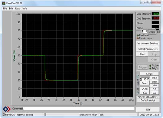
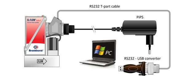
2.8.1 RS232 communication
Using a Windows computer, the instrument can
be monitored and operated via RS-232. For
operation, the free Bronkhorst FlowWare tools
can be used, providing a comprehensive user
interface to the digital instrument functions.
This example uses the following components:
· EL-FLOW® Select
· RS-232 T-part cable (art no. 7.03.366)
· RS-232-USB converter (art no. 9.09.122)
· Windows computer (for readout and control)
· Plug-in Power Supply (PiPS, art no. 7.03.422)
Connect the T-part cable with the 9-pin D-sub connector on the side of the instrument and use the RS-232/USB converter to
connect the other end of the cable with a free USB port of the computer.
For communication with a PLC or other controlling device, a 9-pin D-sub cable with a loose end (part no. 7.03.004,
7.03.536 or 7.03.537) can be used. Consult the RS-232 hook-up diagram to connect the required signals.
For RS-232 communication at baud rates up to 38400 Baud the maximum allowable cable length is 10 m. For higher
baud rates, use a maximum cable length of 3 m.
· For more information about communication through the RS-232 interface, consult the RS-232 manual (document
no. 9.17.027).
· The FlowWare tools and accompanying documentation can be downloaded from the Accessories and software
section on the Bronkhorst® product pages (www.bronkhorst.com/products).
2.8.2 Fieldbus communication
The instrument can be connected to a fieldbus
system with the optional fieldbus connector on
top. At the same time, RS-232 communication
with a Windows computer is possible through
the 9-pin D-sub connector on the side of the
instrument.
This example uses the following components:
· EL-FLOW® Select with DeviceNet™ interface
· DeviceNet™ M12 cable (art no. 7.03.323)
· DeviceNet™ M12 Y adapter (art no. 7.03.319)
· RS-232 cable (art no. 7.03.367)
· RS-232-USB converter (art no. 9.09.122)
· Windows computer (for readout and control)
Note that the used fieldbus components in this
example are specific to DeviceNet™. For connecting with other fieldbus systems, other cables and adapters are needed.
Always check the total power consumption of your instruments before connecting them to a fieldbus system. Do not exceed
the maximum power of the power supply unit.
For all available fieldbus types except PROFIBUS DP, the fieldbus connection on is used to power and operate the
instrument. For PROFIBUS DP, the instrument needs to be powered through the 9-pin D-sub connector on the side of the
instrument as shown in RS232 communication.
Consult the according fieldbus manual for more information about setting up a fieldbus network with Bronkhorst®
instruments.
If you need assistance with setting up a fieldbus system, contactyour Bronkhorst representative for information.
9.17.099H Instruction Manual EL-FLOW® Select 17Bronkhorst®
2.8.3 E-8000 power supply, readout and control
Using an E-8000 module, instruments can be
powered (100…240 Vac) and operated via RS-
232. Most digital parameters and functions are
accessible via the display interface and the
control buttons.
This example uses the following components:
· 2x EL-FLOW® Select
· 2x RS-232/power supply cable (art no.
7.03.016/7.03.538/7.03.539)
· E-8000 power supply, readout and control
module
Consult the E-8000 manual (document 9.17.076) for more information. This manual can be downloaded from the
Accessories and software section on the Bronkhorst® product pages (www.bronkhorst.com/products).
2.8.4 BRIGHT readout and control
Most digital parameters and functions are
accessible via the display interface and control
buttons of a BRIGHT readout and control
module (type B1 or B2). When a BRIGHT module
is installed, no other RS-232 connection can be
established with the instrument.
This example uses the following components:
· EL-FLOW® Select
· BRIGHT readout and control module
· Plug-in Power Supply (PiPS, art no. 7.03.422)
Use the 9-pin D-sub connector on the side of the instrument to plug in the T-part that comes with the BRIGHT module.
Consult the BRIGHT manual (document 9.17.048) for more information. This manual can be downloaded from the
Accessories and software section on the Bronkhorst® product pages (www.bronkhorst.com/products).
18 Instruction Manual EL-FLOW® Select 9.17.099HBronkhorst®
3 Operation
After correct installation of the EL-FLOW® Select and when all safety precautions have been taken into account, the
instrument can be used for measuring and/or controlling mass flow in the system.
3.1 Powering up and powering down
· It is recommended to turn on power before applying fluid pressure and to switch off power only after relieving fluid
pressure.
· For best performance, allow the device to warm up and stabilize for at least 30 minutes before starting measurement
and/or control. This may be done with or without media flow.
When applying pressure, avoid pressure shocks and bring the fluid system gradually up to the level of the specified
operating conditions; open the fluid supply gently.
3.2 First use
In systems for use with corrosive or reactive media, purging for at least 30 minutes with a dry, inert gas (like Nitrogen or
Argon) is absolutely necessary before use. After use with corrosive, reactive or hazardous media (e.g. toxic or flammable),
purging is also necessary before the fluid system is exposed to air.
If the instrument is mounted in a position with upward or downward flow, adjusting the zero point is advised before using
the instrument for the first time. See Adjusting zero point for background information and instructions.
3.3 Mass flow measurement and control
When powering up, the instrument needs a couple of seconds
to start up the electronics. As soon as the start-up sequence
has finished (green LED glows continuously), the instrument is
ready to measure mass flows, however, optimal accuracy is
only reached after warming up (see Powering up and
powering down).
After powering up, the control valve closes (normally open) or
stays closed (normally closed). The valve stays closed until the
instrument receives a setpoint from the active setpoint source.
The internal PID controller then immediately opens the control
valve, until the measured flow rate matches the setpoint. It
maintains the resulting flow rate until another setpoint is
given.
EL-FLOW® Select instruments are most accurate at the specified inlet/outlet pressure, temperature and process gas
conditions. However, the instrument will function properly in a wide range of varying conditions. It is strongly advised to
use the FlowTune™ software available with the instrument to set the correct process conditions if the actual process
conditions differ from the conditions for which the instrument is set (see Changing fluid set).
Although EL-FLOW® Select instruments have excellent temperature stability, the best accuracy is achieved when
temperature gradients across the instruments are avoided. Make sure that the gas temperature matches the ambient
temperature as good as possible and mount the instruments on a rigid (heat conducting) surface.
EL-FLOW® Select instruments handle pressure shocks in the system well, but are not insensitive to pressure fluctuations.
For optimum control stability, provide a stable (pressure controlled) inlet pressure with sufficient buffer volume between
the pressure regulator and the instrument and avoid installing multiple instruments or control valves in close proximity to
another with small volume piping in between.
9.17.099H Instruction Manual EL-FLOW® Select 19Bronkhorst®
3.3.1 Changing fluid set
Optionally, EL-FLOW® Select instruments can provide Multi Fluid/Multi Range functionality (MFMR;
available if and as specified at ordering time). If MFMR is enabled, this is indicated in the lower left
corner of the serial number label.
MFMR enabled instruments are calibrated ex factory for a number of standard measuring ranges, which can be configured
for use with different fluids. Defining fluids and ranges and selecting the active fluid can be done via RS-232 with
FlowTune™.
FlowTune™ provides the following key functionality:
· Definition and storage of up to eight different fluids in the instrument
· Storing fluid properties for any gas
· Changing inlet- and/or outlet pressure based on actual process
conditions
· Re-ranging the full scale (FS) flow rate within the instrument's
supported flow range
· Changing control speed per fluid set for faster or slower (smoother)
flow control
MFMR functionality is available for the full temperature and pressure range of the instrument. FlowTune™ checks the
changes for the following limitations:
· Rangeability of the flow sensor for the selected fluid
· Rangeability of the control valve for the selected fluid
· Accuracy indication for the given flow range
· Compatibility of selected gases with the used sealing materials (see Sealing material compatibility)
· Limitations to the operating conditions
After all limitation checks are passed, the entered properties are stored in the instrument, including the required controller
settings. When switching to another fluid set, controller settings are automatically adjusted to the new process conditions,
so there is no need to change PID controller settings manually.
The FlowTune™ software and the associated documentation can be downloaded from the product pages on the Bronkhorst
website: www.bronkhorst.com/products
To connect with FlowTune™, use RS232 communication via the 9-pin D-sub connector. In case a connection cannot be
established, use the power-up functionality of the multifunctional switch to switch to configuration mode and enable
RS232 communication.
After configuring the required parameters, remember to return the instrument to the original communication mode.
It is advised to use FlowTune™ only in a non-operational environment. FlowTune™ will force the instrument to Valve Safe
State as soon as the connection is made. Be sure to close communication between FlowTune™ and the instrument
properly, to restore the normal operating mode.
20 Instruction Manual EL-FLOW® Select 9.17.099HBronkhorst®
3.4 Valve Safe State
When a controlling instrument is not powered or cannot communicate with the fieldbus network (if applicable), the control
valve automatically returns to its default state (also called Safe State), which is closed for a 'normally closed' valve (n/c) and
fully open for a 'normally open' valve (n/o). Taking into account the typical process conditions under which the instrument
is used (such as the processed media and ambient conditions; see also ), the default state is generally
considered safe.
Check the serial number label or the technical specifications to see which valve type is used on your instrument (if
applicable).
3.5 Manual controls
On top of the housing, the instrument is equipped with two LED indicators and a multifunctional
switch, which can be used to monitor the instrument visually and start several functions manually.
3.5.1 LED indications
The LEDs on top of the instrument indicate the operational state. The meaning of some indications depends on the specific
fieldbus interface of the instrument (if installed).
• (green) Mode: operation mode indication
• (red) Error: error/warning messages
The tables below list the different LED indications:
• Green
Pattern Time Indication
off continuous Power off or program not running
on continuous Normal operation mode
short flash 0.1 sec on, No communication, valves are in safe/default state
2 sec off
blink 0.2 sec on, Special function mode; the instrument is busy performing a special function
0.2 sec off
long flash 2 sec on, Configuration mode; the 9-pin D-sub connector is set for RS-232 communication
0.1 sec off (ProPar) at 38400 Baud
9.17.099H Instruction Manual EL-FLOW® Select 21Bronkhorst®
• Red
Pattern Time Indication
off continuous No error
on continuous Critical error; the instrument needs servicing before it can be used
short flash 0.1 sec on, FLOW-BUS Node occupied: re-install instrument
2 sec off PROFIBUS DP No data exchange between master and slave (automatic recovery)
Modbus Data is being received or transmitted
DeviceNet™ Minor communication error
EtherCAT® Instrument is not in OP mode
PROFINET No application relation established
blink 0.2 sec on, FLOW-BUS Waiting for communication
0.2 sec off PROFIBUS DP Not used
Modbus Not used
DeviceNet™ No bus power
EtherCAT® Not used
PROFINET Not used
long flash 2 sec on, FLOW-BUS Not used
0.1 sec off PROFIBUS DP Requested parameter not available
Modbus Not used
DeviceNet™ Serious communication error; manual intervention needed
EtherCAT® Configuration error
PROFINET Configuration error (e.g. a requested parameter is not available)
• Green and • red (alternating)
Pattern Time Indication
slow wink 1 sec on, Alarm indication; minimum/maximum alarm, power-up alarm, limit reached or batch
1 sec off size reached
normal wink 0.2 sec on, Wink mode; by sending a command to the Wink parameter, the instrument flashes its
0.2 sec off LEDs to indicate its physical location
fast wink 0.1 sec on, Selected action started (after releasing the multifunctional switch)
0.1 sec off
DeviceNet™ instruments have different LED indications, that replace the standard indications described in this section (see
further).
22 Instruction Manual EL-FLOW® Select 9.17.099HBronkhorst®
3.5.1.1 Interface status
Instruments with an EtherCAT® or PROFINET interface are equipped with a third LED (bi-color; green and red), to indicate the
status of the communication interface. This Status LED can give the following indications:
Pattern Time EtherCAT® PROFINET
• off continuous Power off or initializing Interface not (yet) started
• on, green continuous Normal operation Normal operation, application relation
established with I/O controller
•greenblinking, 0.2 sec on,
0.2 sec off
Pre-operational Initializing
• blinking, red 0.2 sec on,
0.2 sec off
Invalid state change Link status OK, no application relation
with I/O controller
•redsingle flash, 0.2 sec on,
1 sec off
Invalid configuration n/a
•reddouble flash, 0.2 sec on,
0.2 sec off,
Communication timeout (e.g.
communication cable disconnected)
n/a
0.2 sec on,
1 sec off
• on, red continuous n/a No link
Ethernet indicators
RJ-45 connection sockets on instruments with a EtherCAT® or PROFINET interface have two integrated LED indicators, with
standard Ethernet functionality:
Amber: Ethernet speed
Green: Ethernet link/activity
3.5.1.2 DeviceNet™ indications
DeviceNet™ instruments have two bi-color LEDs (green/red) to indicate network and module status. The indications below
replace the standard LED indications:
• //• (green/red) Network status (NET; left)
• • (green/red) Module status (MOD; right)
The tables below list the different LED indications:
Network status
Pattern Time Indication
• off continuous Power off or offline
• on, green continuous Online , connected, link OK
•green
blinking, 0.5 sec on,
0.5 sec off
Online, not connected; the instrument is online but has no connections to other
nodes or is not allocated to a master
• blinking, red 0.5 sec on,
0.5 sec off
Connection timed out
• on, red continuous Critical link failure; the device cannot connect to the network
9.17.099H Instruction Manual EL-FLOW® Select 23Bronkhorst®
Module status
Pattern Time Indication
• off continuous No power
• on, green continuous Normal operation mode
•green
blinking, 0.5 sec on,
0.5 sec off
Device is in standby mode or configuration is missing, incomplete or incorrect
• /• alternating 0.5 sec green,
0.5 sec red
Self test mode
• on, red continuous Critical error; the instrument needs servicing before it can be used
3.5.2 Multifunctional switch
Some special functions of the instrument can be started manually using the multifunctional switch near the indication
LEDs. These functions are available in analog as well as in digital operation mode.
3.5.2.1 Normal operating functions
· In order to access these functions, press and hold the switch while the instrument is in normal operation mode (green
LED glowing).
· As long as the switch is held, the LEDs show a repeating sequence of patterns, where each pattern indicates a function.
· All indications in this sequence are continuous.
· Each pattern is shown for a number of seconds; in the table below the column Hold time indicates the time frame within
the sequence where the LEDs show the associated pattern.
· To start a function, release the switch when the LEDs show the pattern of the required function.
•
(green)
•
(red) Hold time Function
off off 0…1 sec No action
off off 1…4 sec 1. In case of a min/max alarm: reset alarm
2. FLOW-BUS: Auto-install to bus - lets instrument obtain free node address if
configured node address is occupied
Note: min/max alarm (if any) has to be reset before auto install can be performed.
off on 4…8 sec Reset instrument; clear all warnings and error messages and restart the instrument
on off 8…12 sec Auto-zero; re-adjust the zero-point of the instrument (flow meters/controllers only)
on on 12…16 sec Enable FLASH mode for firmware update:
· the instrument shuts down and both LEDs are switched off
· at the next power-up, the instrument will be active again
See Adjusting zero point for background information and instructions on how to adjust the zero point of an instrument.
Never perform a zeroing procedure before having taken notice of the instructions.
24 Instruction Manual EL-FLOW® Select 9.17.099HYou can also read