IEC 62591 Wireless Interface Instruction Manual - Form Number D5139 Part Number D301709X012 August 2015 - Remote Automation Solutions
←
→
Page content transcription
If your browser does not render page correctly, please read the page content below
Form Number D5139
Part Number D301709X012
August 2015

IEC 62591 Wireless Interface
Instruction Manual

Remote Automation Solutions
IEC 62591 Wireless Interface Instruction Manual

                                   Revision Tracking Sheet
                                            August 2015

This manual may be revised periodically to incorporate new or updated information. The revision date
of each page appears at the bottom of the page opposite the page number. A change in revision date
to any page also changes the date of the manual that appears on the front cover. Listed below is the
revision date of each page (if applicable):

       Page                   Revision
       All                    August-2015
       All                    August-2014
       All                    August-2012
       Initial issue          July-2012

ii                                                                              Revised August-2015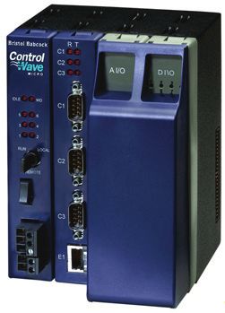
IEC 62591 Wireless Interface Instruction Manual
Chapter 1 – General Information
In This Chapter
1.1 Scope of Manual .................................................................................... 1-2
1.2 Hardware ............................................................................................... 1-2
1.2.1 IEC 62591 Wireless Interface Module ........................................ 1-2
1.2.2 Smart Wireless Field Link........................................................... 1-3
1.2.3 WirelessHART Field Devices ..................................................... 1-4
1.3 Configuration/Commissioning Software ................................................ 1-5
1.4 Additional Technical Information............................................................ 1-5
This manual covers both the hardware – the IEC 62591 Wireless
Interface module for the ControlWave Micro device and the Smart
Wireless Field Link – and the software you need to configure and
commission the hardware components.
This chapter details the structure of this manual and provides an
overview of the IEC 62591 Wireless Interface and its components.
Note: The IEC 62591 Wireless Interface uses open source software.
Refer to Open Source Software Listing (Form A6330, included
in the same .zip file as this manual) for a complete listing of all
components. Source code is available upon request. You may
obtain a copy of this source code by contacting Remote
Automation Solutions Technical Support.
Overview The International Electrotechnical Commission’s 62591 standard
(commonly called WirelessHART®) is a global IEC-approved
standard that specifies an interoperable self-organizing mesh
technology in which field devices form wireless networks that
dynamically mitigate obstacles in the process environment. This
architecture creates a cost-effective automation alternative that does
not require wiring and other supporting infrastructure.
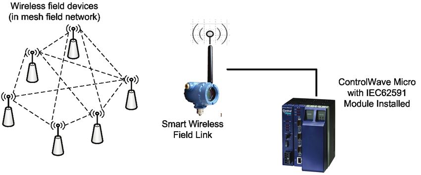
Remote Automation Solutions’ IEC 62591 implementation consists of
an IEC 62591 Wireless Interface module installed in a ControlWave
Micro RTU. The module is wired to a field-installed Smart Wireless
Field Link. The wiring powers the Smart Wireless Field Link and
transmits data between the Smart Wireless Field Link and a number of
field-installed WirelessHART devices. The ControlWave
implementation supports up to 100 devices. (See Figure 1-1, which
shows a ControlWave Micro, a Smart Wireless Field Link, and several
WirelessHART devices).
Revised August-2015 General Information 1-1
IEC 62591 Wireless Interface Instruction Manual

                             Figure 1-1. IEC 62591 Field Installation

1.1 Scope of Manual
                            This manual contains the following chapters:
                             Chapter 1              Provides an overview of the hardware for the IEC
                             General Information    62591 Wireless Interface.
                             Chapter 2              Provides information on installing the IEC 62591
                             Installation           Wireless Interface modules, installing the Smart
                                                    Wireless Field Link, and wiring the Smart Wireless
                                                    Field Link to the module.
                             Chapter 3
                                                    Provides information on using ControlWave Designer
                             Configuring and
                                                    to configure and commission the Wireless Interface.
                             Commissioning
                             Chapter 4
                                                    Provides general troubleshooting tips.
                             Troubleshooting

1.2 Hardware
                            The IEC 62591 Wireless Interface has two basic components: the IEC
                            62591 Wireless Interface module (“module”) and the Smart Wireless
                            Field Link (“Field Link”).

              1.2.1      IEC 62591 Wireless Interface Module
                            The IEC 62591 module has the standard appearance of a ControlWave
                            Micro module (see Figure 1-2).

1-2                                 General Information                             Revised August-2015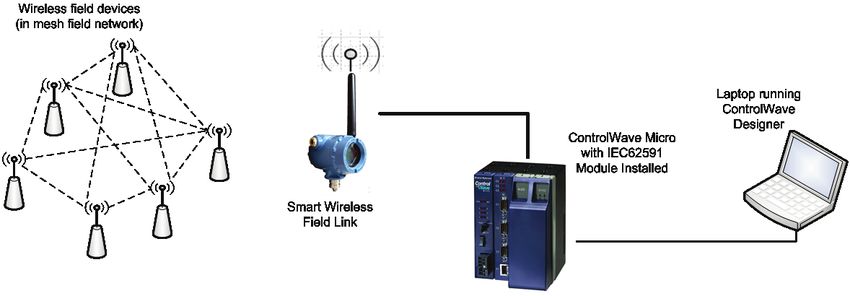
IEC 62591 Wireless Interface Instruction Manual
Figure 1-2. IEC 62591 Wireless Interface Module
You can place the module in any open I/O slot on the ControlWave
Micro except, due to a mechanical restriction, it cannot reside in the last
slot of any housing. Each ControlWave Micro can support only one IEC
62591 Wireless Interface module.
You cannot use the IEC 62591 with the ControlWave Micro
Distributed I/O System.
Note: For information on installing modules in the ControlWave
Micro, refer to the ControlWave Micro Instruction Manual (part
D301392X012).
USB Port The module’s USB port supports firmware upgrades and provides
debug information for product support.
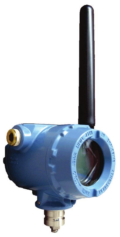
1.2.2 Smart Wireless Field Link
The second component in the Wireless Interface is the Smart Wireless
Field Link (or “field link”; see Figure 1-3). You install the field link
away from controller in the optimal location for best network
performance. A 4-wire connection between the module and field link
provides the 12-30 Vdc power the field link requires and transmits
communication signals sent to the field link from the various
WirelessHART field devices.
Revised August-2015 General Information 1-3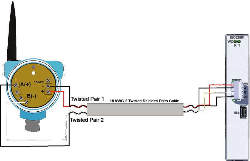
IEC 62591 Wireless Interface Instruction Manual

                                              Figure 1-3. Smart Wireless Field Link

                            For instructions on installing the Smart Wireless Field Link, refer to
                            Chapter 2, Installation.

              1.2.3      WirelessHART Field Devices
                            The two components of Remote Automation Solutions’ IEC 62591
                            Wireless Interface provide you with the ability to manage data from a
                            network of WirelessHART field devices. Remote Automation Solutions
                            supports transmitters that conform to the WirelessHART protocol. The
                            physical configuration of the IEC 62591 Wireless Interface is based on
                            the ControlWave Micro and the total number of field devices. A
                            ControlWave Micro implementation supports up to 100 devices.

                            Note:    The IEC 62591 Wireless Interface Module is designed to return
                                    the process and dynamic variables (PV, SV, TV, QV, slot 0, 1, 2,
                                    3) from any device which meets the IEC 62591 specification
                                    (HCF_SPEC-285, Revisions 2.0). Review the product data sheet
                                    (available on our website) to see a current list of the devices
                                    which Emerson has tested and supports with the interface. If you
                                    have a WirelessHART device which does not appear in the
                                    product data sheet consult with the manufacturer of the device to
                                    determine whether the process variable values you want to
                                    collect are available through the PV, SV, TV, QV and slot 0, 1,
                                    2, and 3. If the device meets the discrete control specification, it
                                    should work with the IEC 62591 Wireless Interface;
                                    alternatively, it may be treated like an analog wireless device.
                                    Always test any WirelessHART devices not listed to see whether
                                    they work with the IEC 62591 Wireless Interface before you
                                    install them in the field.

1-4                                 General Information                            Revised August-2015
IEC 62591 Wireless Interface Instruction Manual

1.3 Configuration/Commissioning Software
                            Once you have installed the modules and wired them to the Smart
                            Wireless Field Link, you use ControlWave Designer and either AMS
                            Device Configurator (a component of Emerson Process Management
                            Field Tools) or a 375/475 Field Communicator to configure and then
                            commission (“activate”) the entire network. Refer to Chapter 3,
                            Configuring and Commissioning, for specific instructions.

1.4 Additional Technical Information
                            Refer to the following documents for additional technical information:

                            Note: The most current versions of these technical publications are
                                    available at www.EmersonProcess.com/Remote.

                                   Table 1-1. Additional Technical Information

                            Name                                 Form Number          Part Number
   ControlWave Micro IEC 62591 Interface                          CWM:62591           D301714X012
   Emerson Process Management Field Tools Quick Start Guide          D5141            D301703X412

Revised August-2015                        General Information                                    1-5
IEC 62591 Wireless Interface Instruction Manual
[This page is intentionally left blank.]
1-6 General Information Revised August-2015IEC 62591 Wireless Interface Instruction Manual
Chapter 2 – Installation
In This Chapter
2.1 Installing the IEC 62591 Module ......................................................2-1
2.2 Installing the Smart Wireless Field Link ...........................................2-2
2.2.1 Optimizing the Location ........................................................2-2
2.2.2 Positioning the Antenna .......................................................2-2
2.2.3 Mounting the Field Link ........................................................2-3
2.3 Wiring the Module and Field Link ....................................................2-4
2.3.1 Wiring the Field Link .............................................................2-4
2.3.2 Wiring the IEC 62591 Module ..............................................2-5
2.4 Configuring Wireless Devices for the Network ................................2-7
2.5 Preparing for Configuration and Commissioning ...........................2-10
This chapter describes installing the IEC 62591 module in a
ControlWave Micro, installing the Smart Wireless Field Link, and
connecting the Smart Wireless Field Link to the IEC 62591 Wireless
Interface module.
Note: This chapter covers the physical installation process. To
configure and commission the IEC 62591 Wireless Interface,
refer to Chapter 3, Configuring and Commissioning.
2.1 Installing the IEC 62591 Module
You install the IEC 62591 Wireless Interface module in the
ControlWave Micro as you would any other module. However, you can
install only one IEC 62591 module.
Notes:
Only ControlWave Micro’s with 05.50 (or newer) system firmware
support the IEC 62591 module. Version 5.70 (or newer) system
firmware is required for discrete control.
You can install the IEC 62591 module in any I/O slot (slot 3 or
higher except for the last slot in any chassis/housing) in the
ControlWave Micro. You cannot use the IEC 62591 with the
ControlWave Micro Distributed I/O System.
1. Disconnect power from the ControlWave Micro.
2. Choose an open I/O slot (except for the last slot of any housing).
3. Locate the built-in guides on the top and bottom of the housing.
4. Gently slide the IEC 62591 module into the housing until it seats
into the connectors on the interior back of the housing.
5. Restore power to the unit.
Revised August-2015 Installation 2-1IEC 62591 Wireless Interface Instruction Manual
2.2 Installing the Smart Wireless Field Link
This section covers where and how to install the Smart Wireless Field
Link.
2.2.1 Optimizing the Location
Mount the Field Link in a location that provides convenient access to
the host system network (wireless I/O devices) and the network of
wireless field devices. Find a location where the Field Link has optimal
wireless performance. Ideally, this is 4.6 to 7.6 m (15-25 ft) above the
ground or 2 m (6 ft) above obstructions or major infrastructures. See
Figure 2-1.
Figure 2-1. Mounting the Field Link
2.2.2 Positioning the Antenna
Position the antenna vertically, either straight up or straight down,
approximately 1 m (3 ft) from any large structure, building, or
conductive surfaces to allow clear communication with other devices.
See Figure 2-2.
2-2 Installation Revised August-2015IEC 62591 Wireless Interface Instruction Manual
Figure 2-2. Antenna Position
2.2.3 Mounting the Field Link
You typically mount the Field Link on a pipe or mast using the clamps
provided in the kit (see Figure 2-3).
1. Attach the L-shaped bracket to the pipe or mast.
• For pipe installations, insert the larger U-bolt around the 2-in.
pipe, through the L-shaped bracket, and through the washer plate
(see the left side of Figure 2-3). Use a ½-in. socket-head wrench
to secure the nuts to the U-bolt.
• For mast installations, bolt the L-shaped bracket securely to the
mast (see the right side of Figure 2-3).
2. Insert the smaller U-bolt around the base of the Field Link and
through the L-shaped bracket.
3. Use a ½-in. socket-head wrench to fasten the nuts to the U-bolt.
Revised August-2015 Installation 2-3IEC 62591 Wireless Interface Instruction Manual
Figure 2-3. Field Link Mounting
2.3 Wiring the Module and Field Link
This section assumes you have already installed the IEC 62591 module
in the ControlWave Micro and installed the Smart Wireless Field Link
in its permanent field location.
Communications between the IEC 62591 module and the Field Link
occur through an RS-485 connection. Remote Automation Solutions
recommends that you use shielded, twisted-pair cable for I/O signal
wiring. The twisted-pair minimizes signal errors caused by electro-
magnetic interference (EMI), Radio Frequency Interference (RFI), and
transients. The removable terminal blocks on the module accept wire
sizes up to 14 AWG.
Note: Ensure that wiring between the ControlWave Micro IEC 62591
module and the Smart Wireless Field Link meets all appropriate
local requirements (use of conduit, etc.).
2.3.1 Wiring the Field Link
1. Power down the IEC 62591 module (if it is currently powered).
2. Remove the housing cover identified on the casing as “Field
Terminals.”
3. Connect the positive power lead to the “+” power terminal and the
negative power lead to the “–” power terminal.
4. Connect the data + lead to the “A (+)” terminal and the data – lead
to the “B (–)” terminal (see Figure 2-4).
2-4 Installation Revised August-2015IEC 62591 Wireless Interface Instruction Manual
5. Plug and seal any unused conduit connectors.
6. Replace the housing cover.
C
A
D
B
A. Data A (+)
B. Data B (–)
C. Return
D. +10.5 to 30 Vdc
Figure 2-4. Field Link Power and Data Wiring
2.3.2 Wiring the IEC 62591 Module
Figure 2-5 provides a wiring diagram for the IEC 62591 module.
You must connect an RS-485 cable between the RS-485 port on the
module, and the Smart Wireless Field Link. This requires a Belden 2-
twisted pair cable. Table 2-1 shows connections for the twisted pair
cable. You must also connect termination jumper wires as shown in
Figure 2-6.
Revised August-2015 Installation 2-5IEC 62591 Wireless Interface Instruction Manual
Table 2-1. RS-485 Cable Connections
Smart Wireless Field Link IEC 62591 Module
A(+) A
B(-) B
POWER - GND
POWER + PWR
Figure 2-5. IEC 62591 Module Power and Data Wiring
2-6 Installation Revised August-2015IEC 62591 Wireless Interface Instruction Manual
Termination Jumpers
Figure 2-6. IEC 62591 Module – Connecting Termination Jumpers
2.4 Configuring Wireless Devices for the Network
See the product data sheet (available on our website) for a list of devices
Emerson has tested with the IEC 62591 Wireless Interface.
You must configure the following for each device in the wireless
network:
A long tag name which is unique in the wireless network
A Network ID (must be the same for every device in the wireless
network)
A Join Key (must be same for every device in the wireless network)
Caution Configure all devices belonging to a site to use the same Network ID
and join key. To avoid network errors, configure all devices in adjacent
networks to use a different Network ID and join key.
You configure these using the 375 or 475 Field Communicator or using
AMS Device Configurator (a component of Field Tools software). If
you have AMS Device Configurator software, see its online help for
details on how to do this.
Revised August-2015 Installation 2-7IEC 62591 Wireless Interface Instruction Manual
Basic instructions for setting the long tag, Network ID and Join Key
using the 375 Field Communicator are included below; see the Field
Communicator user manual if you need more information.
1. Connect the Field Communicator clips to the communication
connectors on the wireless device, and turn the communicator on.
From the Main Menu, double-tap HART Application.
375 Main Menu
HART Applicationnnnnnnnnnnnnnnnnnnn
FOUNDATION Fieldbus Application
Settings
Listen For PC
ScratchPad
2. When the HART application detects the device you want to
configure, double-tap on it.
HART Applicationnnnnnnnnnnnnnnnnnnn
Online
0:WHART01nnnnnnnnnnnnnnnnnnnnnnn
3. From the Online Menu, double-tap Configure.
Online
1 Overview
2 Configure nnnnnnnnnnnnnnnnnnnnnnn
3 Service Tools
4. From the Configure Menu, double-tap Manual Setup.
Configure
1 Guided Setup
2 Manual Setup nnnnnnnnnnnnnnnnnnnn
3 Alert Setup
2-8 Installation Revised August-2015IEC 62591 Wireless Interface Instruction Manual
5. From the Manual Setup Menu, double-tap Wireless.
Manual Setup
1 Wirelessnnnn nnnnnnnnnnnnnnnnnnnn
2 Process Sensor
3 Percent of Range
4 Device Temperatures
5 Device Information
6 Device Display
7 Other
6. From the Wireless Menu, double-tap either:
a. Network ID to set the Network ID using the on-screen keypad.
b. Join Device to Net… to set the Join Key using the on-screen
keypad.
Wireless
1 Network ID
2 Join Device to Net…
3 Broadcast Rates
4 Configure Broadca…
5 Power Mode
6 Power Source
7. From the Manual Setup Menu (shown in Step 7), double-tap Device
Information to call up the Device Information menu, then choose
Long Tag to set the long tag using the on-screen keypad.
Device Information
1 Tag
2 Long Tagxxxxxxxxxxxxxxxxxxxxxxxxxxx
3 Device
4 Sensor
5 Wireless
8. When you’re finished with your configuration, tap SAVE, and
choose to save the changes to the Internal Flash memory of the
device and tap SAVE again.
Save as…
1 LocationnnnnnnnnnnnnnnInternal Flash
2 Name WHART01
3 Config Type Device
Revised August-2015 Installation 2-9IEC 62591 Wireless Interface Instruction Manual
2.5 Preparing for Configuration and Commissioning
Once you have completed the wiring between the Field Link and the
ControlWave Micro, re-attach the plastic bezel covers and apply power
to the ControlWave Micro.
Proceed to Chapter 3.
2-10 Installation Revised August-2015IEC 62591 Wireless Interface Instruction Manual
Chapter 3 – Configuration and Commissioning
In This Chapter
3.1 Overview ..........................................................................................3-2
3.1.1 Configuring Devices and Planning the Network ...................3-2
3.1.2 Network ID and Join Key ......................................................3-3
3.1.3 Rosemount THUM™ Adapter................................................3-3
3.1.4 Active List and Commission List...........................................3-4
3.2 IEC 62591 Sample Program(s)........................................................3-4
3.2.1 Before You Begin .................................................................3-5
3.2.2 Accessing the IEC 62591 Sample Program(s).....................3-5
3.2.3 Modifying the IEC62591_STRUCTS Datatypes
Worksheet ............................................................................3-7
ACTIVE_DEVICES_ARRAY datatype .................................3-7
COMMISSION_ARRAY_DISCRETE datatype -or-..............3-7
INACTIVE_STAT_ARRAY and LAST_STATE_ARRAY
datatypes ..............................................................................3-8
3.2.4 ErrorCatch Function Block (OPTIONAL) ..............................3-8
3.2.5 Modifying the DevData Function Block (OPTIONAL)...........3-8
3.2.6 Modifying the ACT_LIST Function Block (OPTIONAL) ......3-10
3.2.7 Configuring the Commission List........................................3-11
3.2.8 Specifying the Join Key ......................................................3-12
3.2.9 Specifying the Network ID and Slot Number ......................3-13
3.2.10 Configuring the Statistics List (OPTIONAL) .......................3-13
3.2.11 Generating Alarms Based on IEC62591 Function
Block Status (OPTIONAL) ..................................................3-14
3.2.12 Additional Programming Notes...........................................3-14
3.3 Commissioning Wireless Devices..................................................3-15
3.3.1 Active Advertising ...............................................................3-16
3.4 Decommissioning or Replacing Wireless Devices ........................3-16
3.5 WirelessHART Data Access and Statistics ...................................3-16
3.5.1 WirelessHART Data Access...............................................3-16
3.5.2 WirelessHART Communication Statistics ..........................3-18
3.6 Upgrading Firmware in the IEC 62591 Wireless
Interface Module ............................................................................3-18
In addition to wiring the Field Link to the IEC 62591 module and
applying power to the module, you need to configure your ControlWave
project to access the wireless network so it can discover and
commission each WirelessHART device in the entire network. You also
need to individually configure each WirelessHART device that will
belong in the network with a unique long tag name and a common
Network ID and common Join Key.
Note: Refer to the Emerson Process Management Field Tools Quick
Start Guide (part D301703X412) for instructions on using AMS
Device Configurator to configure the WirelessHART devices
with the long tag name, Network ID, and Join Key.
Keep in mind that configuration and commissioning is a two-step
process for each device:
Revised August-2015 Configuration and Commissioning 3-1IEC 62591 Wireless Interface Instruction Manual
One step is to configure each device using Field Tools’ AMS Device
Configurator and a HART modem (or you can use a hand-held
configuration device such as the Emerson 375 or 475 Field
Communicator. During this step you individually add network
information (Network ID, Join Key, and long tag name) to the field-
based wireless device.
The other step is to use ControlWave Designer to program the
ControlWave Micro so it can detect the network and activate (or
“commission”) each device.
3.1 Overview
As indicated previously, a wireless interface network consists of a
number of wireless devices, a Smart Wireless Field Link, and an IEC
62591 module installed in a ControlWave Micro. The IEC 62591
module can communicate with a maximum of 100 wireless devices; the
actual number allowed for a given application varies depending upon
the burst rate. An eight second burst rate allows the full number of 100
devices, a faster burst rate, say one second, reduces the number of
devices allowed.
For the configuration and commissioning tasks described in this chapter,
we use a PC running ControlWave Designer.
Figure 3-1. Wireless Interface
3.1.1 Configuring Devices and Planning the Network
Before you can use a WirelessHART device, you must first configure it.
For this task you may use Field Tools’ AMS Device Configurator and a
HART modem (or you can use a field communicator (such as
Emerson’s 375 or 475 Field Communicator. Ideally, you commission
individual devices at a workbench in a protected environment; although
you can field-commission a device you might add to the network.
During the configuration, you identify the Network ID to which the
device eventually belongs and provide the network-specific Join Key
(see Network ID and Join Key).
3-2 Configuration and Commissioning Revised August-2015IEC 62591 Wireless Interface Instruction Manual
During configuration, you must also give the wireless device a unique
long tag name based on its use or location (such as PMP1TEMP,
PMP2PRES, or WEL02LVL).
Notes:
Tag names must not exceed 32 characters, and the tag name must be
unique for this wireless network.
You must configure the tag name as a long tag name. All references
to tag names in this manual refer to the long tag name.
We recommend you use all CAPITAL LETTERS for the tag names
to avoid confusion since that is how they are stored internally.
The individual devices should fit into a general organizational plan for
your fields. By identifying logical groups and pre-assigning devices to
those groups, you can eliminate guesswork during commissioning,
efficiently define networks, and more quickly begin to acquire data.
Note: An important restriction in planning networks is to know that a
network can have only one Network ID, one Join Key, one Field
Link, and one controller (a ControlWave Micro supporting up to
100 devices).
3.1.2 Network ID and Join Key
A five character Network ID defines one logical grouping of
WirelessHART devices, all of which send their information to one Field
Link. (You define a device’s Network ID when you first configure the
device.) Valid values for the Network ID range from 1 to 36863.
Note: A Network ID or Join Key cannot be all zeros (such as 00000).
The Join Key is the password that allows a device to access its defined
network. During configuration, you also provide the device with its
network-specific Join Key. When you configure your ControlWave
project using ControlWave Designer, you will need to know the
Network ID and Join Key for this network.
3.1.3 Rosemount THUM™ Adapter
Note: Each THUM adapter supports only one wired HART device.
Rosemount’s THUM™ Adapter provides wireless connectivity to a
wired HART device. If you have already commissioned a wired HART
device into your network and want to connect it to a THUM Adapter,
you must first decommission the device, attach the THUM Adapter, and
then re-commission the device. For further information about THUM
Adapters, refer to:
Smart Wireless THUM™ Adapter Reference Manual, 00809-0100-4075,
Rev CA, March 2014
Revised August-2015 Configuration and Commissioning 3-3IEC 62591 Wireless Interface Instruction Manual
Smart Wireless THUM™ Adapter Quick Installation Guide, 00825-0100-
4075, Rev DA, July 2011.
Note: The Quick Installation Guide was packed in the box with the
THUM; the Reference Manual is available on the Rosemount
website (www.EmersonProcess.com/Rosemount).
3.1.4 Active List and Commission List
When the Smart Wireless Field Link detects a wireless device that has
the correct Network ID and Join Key, the IEC 62591 program running
in the ControlWave Micro stores information about that device in a
structure called the Active List. The Active List represents the entire
network of wireless devices from which the Smart Wireless Field Link
could potentially collect process variable data.
The program compares tag names for devices in the Active List to
another structure called the Commission List. If a device in the Active
List has a matching tag name in the Commission List, and its associated
decommission flag is FALSE, the program stores configuration and
process variable data for the device in the Commission List. The device
is then considered to be “commissioned” as an active device in the
network.
3.2 IEC 62591 Sample Program(s)
The ControlWave Designer software includes sample IEC 62591
programs that you can refer to or modify when creating your own IEC
62591-capable application. Alternatively, you can copy all the POUs,
structures, and variables from one of the sample IEC 62591 programs
into an existing ControlWave Designer project.
The sample programs include the IEC62591 function block, as well as
structure and type definitions needed for the commission list, active list,
and statistics list.
Note: For details on specific parameters in the IEC62591 function
block, please refer to the ACCOL3 online help in ControlWave
Designer.
3-4 Configuration and Commissioning Revised August-2015IEC 62591 Wireless Interface Instruction Manual
3.2.1 Before You Begin
Note: Some of the structure data types used in the IEC 62591 sample
programs have changed over time to add functionality. In
particular, ControlWave Micro firmware version 5.70 includes
modifications for discrete control functionality that make
ControlWave projects built to run with version 5.60 firmware
incompatible with 5.70. To upgrade these applications, you must
replace the COMMISSION_ARRAY and COMMISSION_POINT
structure data types with the COMMISSION_ARRAY_DISCRETE
and COMMISSION_POINT_DISCRETE structure data types, and
then re-compile the projects. These new data type definitions are
available in the ACCOL3 Online Help for the IEC62591
function block in 5.70 or in the IEC62591_DIO_Example.zwt sample
project. You do not need to modify your application if you are
not upgrading the existing firmware (version 5.60 or earlier).
In addition to familiarity with ControlWave Designer programming, you
will need to know the following information prior to modifying one of
the sample programs.
The Network ID for the wireless network
The Join Key for the wireless network
The unique long tag names assigned to each wireless device
The slot number in the ControlWave Micro that holds the IEC
62591 module
The maximum number of wireless devices in your wireless network.
We recommend you specify a maximum number that includes room
for growth of the network, in case you add a few more devices later.
3.2.2 Accessing the IEC 62591 Sample Program(s)
1. Start ControlWave Designer.
2. Click File >Open Project/Unzip Project
3. If not already there, navigate to the OpenBSI/Projects area and open
one of the IEC62591 sample projects.
Table 3-1. IEC 62591 Sample Programs
Sample Program Name Description
Addition of support for discrete control. (Use
IEC62591_DIO_Example.zwt
with CW Micro firmware 5.70 or newer)
Original version of IEC 62591 sample project
IEC62591_Example.zwt
(Use with CW Micro firmware 5.60 or earlier)
Revised August-2015 Configuration and Commissioning 3-5IEC 62591 Wireless Interface Instruction Manual
Notes:
The structures and names shown in the following sections are
representative of the original IEC 62591_Example.zwt project;
subsequent sample projects may have variations in names but the
purpose of the basic structures and variables (commission list, active
list, join key, etc.) remains the same.
See the program comments in the sample projects for the most
current information.
4. When you open the project, you can see the project tree. Figure 3-2
shows the different worksheets in the project tree.
The ACTIVE_DEVICES_ARRAY,
COMMISSION_ARRAY,
INACTIVE_STAT_ARRAY, and
LAST_STATE_ARRAY are defined / modified
in this worksheet.
The ErrorCatch function
block definition is in this The DevData function block definition is in
worksheet. ErrorCatch this worksheet. It copies data from one of the
allows you to capture internal structures used by the program to a
error codes that only LIST that you can collect with DataView,
appear for a single task Harvester, or other software.
execution before they are
The Act_List function block definition is in
reset.
this worksheet. It copies data from the Active
List to a LIST that you can collect with
DataView, or other software.
The Clist program definition is in this
worksheet. It initializes the Commission List.
You set the Network ID, You must edit this program. For each device,
you must enter tag names and set the
(IEC62591_NETID) and Slot
decommission flag FALSE.
Number (IEC62591_SLOT) in
the CONSTANTS section of
The wireless program definition is in this
this variables worksheet. worksheet. You must specify the Join Key
“strJoinKey” here. The statistics list is
defined here too. This is also where function
block calls to DevData, ErrorCatch, and
Act_List occur.
In the Global_Variables worksheet,
you specify the list number of the
Active List (ACTIVE_LISTNUM), the
list size for the Active List
(ACTIVE_LIST_SIZE) as well as the
list size for the Commission List
(COMM_LIST_SIZE).
Figure 3-2. IEC 62591 Example – Project Tree
The next several sections outline how to modify the various worksheets
in the project tree to meet the needs of your wireless network.
3-6 Configuration and Commissioning Revised August-2015IEC 62591 Wireless Interface Instruction Manual
3.2.3 Modifying the IEC62591_STRUCTS Datatypes Worksheet
The IEC62591_STRUCTS datatypes worksheet defines the data types
used by the program.
Double-click the IEC62591_STRUCTS worksheet to open it.
Caution Do not modify the datatypes themselves or your IEC 62591 program will
not function correctly. You should only define the sizes of specific
arrays.
You only modify the sizes of the array data types – these sizes vary
depending upon the number of devices in the wireless network.
ACTIVE_DEVICES_ARRAY datatype
The ACTIVE_DEVICES_ARRAY datatype defines an array of active
points that make up the Active List structure. The Active List maintains
identification information on each wireless device discovered by the
field link.
Specify the array size to be equal to the maximum number of wireless
devices you expect to exist in the network. This number should match
the value of the ACTIVE_LIST_SIZE variable in the Global_Variables
sheet.
TYPE
ACTIVE_DEVICES_ARRAY : ARRAY [1..?] OF ACTIVE_POINT;
END_TYPE
COMMISSION_ARRAY_DISCRETE datatype -or-
COMMISSION_ARRAY datatype
Either or these datatypes defines an array of commission points that
make up the Commission List structure. Which datatype you use
depends on your application:
Notes:
COMMISSION_ARRAY_DISCRETE, and
COMMISSION_POINT_DISCRETE datatypes are used in the
IEC62591_DIO_Example.zwt project. These structures are required
for discrete I/O control. (5.70 or newer ControlWave Micro
firmware)
The COMMISSION_ARRAY and COMMISSION_POINT
datatypes are used in the original IEC62591_Example.zwt project.
(5.60 or earlier ControlWave Micro firmware)
The Commission List holds a long tag name and a decommission flag
for each device you intend to collect data from in your network. For any
wireless device in the Commission List that has a matching tag name to
a device in the Active List (meaning it was detected by the Smart
Wireless Field Link) and its decommission flag is FALSE, the
Revised August-2015 Configuration and Commissioning 3-7IEC 62591 Wireless Interface Instruction Manual
Commission List also stores configuration information and actual
process variable data.
Specify the commission array size to be equal to the maximum number
of commissioned devices you expect to exist in the network. This
number should match the value of the COM_LIST_SIZE variable in the
Global_Variables sheet.
TYPE
COMMISSION_ARRAY_DISCRETE : ARRAY [1..?] OF
COMMISSION_POINT_DISCRETE;
END_TYPE
Or
TYPE
COMMISSION_ARRAY : ARRAY [1..?] OF COMMISSION_POINT;
END_TYPE
where “?” is the maximum expected number of devices (including
future expansion) for your network.
INACTIVE_STAT_ARRAY and LAST_STATE_ARRAY
datatypes
The INACTIVE_STAT_ARRAY and LAST_STATE_ARRAY are a
pair of optional arrays that hold statistics about transmitter
communication failures. Both these arrays (if used) should be sized to
be equal to the maximum number of commissioned devices you expect
to exist in the network. This number should match the value of the
COM_LIST_SIZE variable in the Global_Variables sheet.
TYPE
INACTIVE_STAT_ARRAY : ARRAY [1..?] OF INT;
END_TYPE
TYPE
LAST_STATE_ARRAY : ARRAY [1..?] OF BOOL;
END_TYPE
3.2.4 ErrorCatch Function Block (OPTIONAL)
The ErrorCatch function block is called from within the Wireless
worksheet. It maintains counts for different types of configuration errors
and status conditions. There is no need to modify it. The ErrorCatch
function block stores the error counts in the list specified by the
ERROR_CATCH_LISTNUM variable in the Global_Variables
worksheet.
3.2.5 Modifying the DevData Function Block (OPTIONAL)
The various structures in the IEC 62591 program are maintained
internally; they cannot be collected by external utilities such as
DataView. To support this sort of data collection, the IEC 62591
program does include a special function block (DevData) that copies
specific device data from the Commission array to a LIST structure that
can be collected by an external program such as DataView.
3-8 Configuration and Commissioning Revised August-2015IEC 62591 Wireless Interface Instruction Manual
As written in the original IEC62591_Example.zwt project, the DevData
function block copies the following ten items from the
COMMISSION_ARRAY.
Item Description
TagName The unique long tag name assigned to the device (up to 32
characters)
bActive A flag which indicates communication with the device
PV Primary process variable from the device (1st variable)
SV Secondary process variable from the device (2nd variable)
TV Tertiary process variable from the device (3rd variable)
QV Quaternary process variable from the device (4th variable)
Slot0Var, Wireless devices include a series of variables called “slots”
Slot1Var, which hold process data for the device such as temperature,
Slot2Var, pressure, scaling factors, altitude, flow, and so on. You can use
Slot3Var the SlotxVar items to specify up to four of these slots for
collection from the device. Consult the documentation for the
wireless device for information on which slots hold which
variables.
If you decide that you don’t want all of these items in the LIST
structure, or you want to choose one or more different items from the
list, you can modify the DevData function block definition.
To do this, double-click the DevData worksheet to open it.
For example, if you decided that you didn’t want the Slot3Var, and
instead you wanted the serial number of the device you would do the
following:
Change the ianyElement10 entry in the LIST structure to reference
SerialNum instead of slot3Var. (To see the exact names of the different
items you can choose for entries in the LIST structure, click on the
IEC62591_STRUCTS worksheet and review the
COMMISSION_POINT_DISCRETE or COMMISSION_POINT
structure definitions.)
LIST010_1(iiListNumber:= inputListNum,
ianyElement1:= TagName,
ianyElement2:= bActive,
ianyElement3:= PV,
ianyElement4:= SV,
ianyElement5:= TV,
ianyElement6:= QV,
ianyElement7:= slot0Var,
ianyElement8:= slot1Var,
ianyElement9:= slot2Var,
ianyElement10:= SerialNum);
listStatus:=LIST010_1.odiStatus;
Now change the DEMUX function call for the tenth item to reference
the serial number parameter of the COMMISSION_POINT structure
instead of the iorSlot3 parameter:
DEMUX_10(ianyInput := commissionList[inputDevNum].odiSerialNumber,
iiSelect := 10,
iiOutlist := inputListNum);
demuxStat := DEMUX_10.odiStatus;
Revised August-2015 Configuration and Commissioning 3-9IEC 62591 Wireless Interface Instruction Manual
Now, instead of the slot3var value, the device serial number is copied.
Another possible modification you could make, if you wanted to copy
more than ten items, would be to use a larger size LIST definition, say
LIST30 or LIST100. Remember that if you do this, you must define the
destination list to be the same type.
You may also choose to replace these LIST function blocks with the
lists defined using ControlWave Designer’s Variable Extension Wizard
and its resulting _LIST.INI file.
3.2.6 Modifying the ACT_LIST Function Block (OPTIONAL)
The Active List is a list maintained by the IEC62591 function block of
all wireless devices detected by the Smart Wireless Field Link. The
purpose of the ACT_LIST function block is to copy the contents of the
Active List to another LIST that can be collected by external software
such as DataView.
Note: In the IEC62591_DIO_Example.zwt project, the ACT_LIST
function block is called ActiveList.
The only thing you might modify for this is the LIST function block that
is part of the ACT_LIST function block. By default, it uses a LIST020
function block which can have up to 20 elements – this allows a
maximum of ten devices (defined by two elements for the tag name and
device ID) in the active list. You can change this if you need to.
To do this, double-click the Act_List worksheet to open it.
LIST020_1( iiListNumber := inputListNum,
ianyElement1 := Tag_1,
ianyElement2 := DevId_1,
ianyElement3 := Tag_2,
ianyElement4 := DevId_2,
ianyElement5 := Tag_3,
ianyElement6 := DevId_3,
ianyElement7 := Tag_4,
ianyElement8 := DevId_4,
ianyElement9 := Tag_5,
ianyElement10 := DevId_5,
ianyElement11 := Tag_6,
ianyElement12 := DevId_6,
ianyElement13 := Tag_7,
ianyElement14 := DevId_7,
ianyElement15 := Tag_8,
ianyElement16 := DevId_8,
ianyElement17 := Tag_9,
ianyElement18 := DevId_9,
ianyElement19 := Tag_10,
ianyElement20 := DevId_10);
listStatus := LIST020_1.odiStatus;
Suppose, for example, that you needed to allow up to 50 devices in the
active list?
ControlWave Designer supports LIST010, LIST020, LIST030,
LIST050, and LIST100 function blocks. The easiest way to
accommodate 50 devices is to replace the LIST020 function block with
3-10 Configuration and Commissioning Revised August-2015IEC 62591 Wireless Interface Instruction Manual
a single LIST100 function block. In the code, below, we don’t show
devices 11 through 45 for space reasons:
LIST100_1( iiListNumber := inputListNum,
ianyElement1 := Tag_1,
ianyElement2 := DevId_1,
ianyElement3 := Tag_2,
ianyElement4 := DevId_2,
ianyElement5 := Tag_3,
ianyElement6 := DevId_3,
ianyElement7 := Tag_4,
ianyElement8 := DevId_4,
ianyElement9 := Tag_5,
ianyElement10 := DevId_5,
ianyElement11 := Tag_6,
ianyElement12 := DevId_6,
ianyElement13 := Tag_7,
ianyElement14 := DevId_7,
ianyElement15 := Tag_8,
ianyElement16 := DevId_8,
ianyElement17 := Tag_9,
ianyElement18 := DevId_9,
ianyElement19 := Tag_10,
ianyElement20 := DevId_10
:
:
ianyElement91 := Tag_46,
ianyElement92 := DevId_46,
ianyElement93 := Tag_47,
ianyElement94 := DevId_47,
ianyElement95 := Tag_48,
ianyElement96 := DevId_48,
ianyElement97 := Tag_49,
ianyElement98 := DevId_49,
ianyElement99 := Tag_50,
ianyElement100 := DevId_50);
listStatus := LIST100_1.odiStatus;
If you need to support the maximum number of devices – 100 – you can
do this by chaining together two LIST100 function blocks. To do this,
you just use the same iiListNumber parameter for each; that connects
the two to allow for a 200 element list.
3.2.7 Configuring the Commission List
When the Smart Wireless Field Link detects a wireless device that can
be included in the network, it adds information about that device to the
Active List. Process data from the device is only collected if it has a
matching tag name in the Commission List, and if its decommission flag
is FALSE – only then will its data be collected.
Notes:
The Commission List structure in the IEC62591_DIO_Example.zwt
project uses the COMMISSION_ARRAY_DISCRETE datatype, the
the CommisList POU worksheet, and the CommissionListDiscrete
array. (Use with ControlWave Micro firmware 5.70 or newer)
The Commission List structure in the IEC62591_Example.zwt
project uses the COMMISSION_ARRAY datatype, the Clist POU
worksheet, and the CommissionList array. (Use with ControlWave
Micro firmware 5.60 or earlier)
Revised August-2015 Configuration and Commissioning 3-11IEC 62591 Wireless Interface Instruction Manual
You must create an entry in the Commission List that includes the long
tag name for the device, and decommission flag (set to FALSE) for each
and every device you want the IEC 62591 module to access.
To do this, double-click the CommisList (or Clist) worksheet to open it,
then add or modify Commission List definitions to include a valid long
tag name for each iostrTagName and specify FALSE for the
ibDecommission flag for each device you want to commission. Specify
TRUE for the ibDecommission flag only if you don’t want to
commission the device – for example, if it’s not ready to be added to
your system yet.
In the code below, devices DEV_0001, DEV_0002, DEV_0003 and
DEV_0004 all have their ibDecommission flag set to FALSE, so they
all can be commissioned and have process variable data collected over
the network; DEV_0005 has a decommission flag set to TRUE, so it
cannot be commissioned, and its process data won’t be collected unless
that decommission flag is changed to FALSE.
IF (bInitCommList = TRUE) THEN
bInitCommList := FALSE;
commissionList[1].iostrTagName := 'DEV_0001'; (* Tagname in wireless transmitter. *)
commissionList[1].ibDecommission := FALSE; (* Commission the device when found. *)
commissionList[2].iostrTagName := 'DEV_0002';
commissionList[2].ibDecommission := FALSE;
commissionList[3].iostrTagName := 'DEV_0003';
commissionList[3].ibDecommission := FALSE;
c
commissionList[4].iostrTagName := 'DEV_0004';
commissionList[4].ibDecommission := FALSE;
commissionList[5].iostrTagName := 'DEV_0005';
commissionList[5].ibDecommission := TRUE; (* Device is commissioned only after
* this is changed to FALSE. *)
END_IF;
There are other parameters in the Commission List that populate
automatically when the program sees a match between the long tag
names in the Commission List, and the long tag names in the Active
List – the iostrTag Name and ibDecommission flag are the only portions
you create or modify.
If, for some reason, you want to temporarily prevent data collection
from a device in your wireless network, you can just set its
decommission flag to TRUE.
3.2.8 Specifying the Join Key
All wireless devices in your wireless network share the same Join Key.
You must also specify the same Join Key in your ControlWave project.
You specify the Join Key in the Wireless worksheet.
Double-click on the Wireless worksheet and specify the Join Key using
the strJoinKey variable.
3-12 Configuration and Commissioning Revised August-2015IEC 62591 Wireless Interface Instruction Manual
strJoinKey := '12345678-00000000-00000000-00000000';
3.2.9 Specifying the Network ID and Slot Number
The wireless network of devices detected by the Smart Wireless Field
Link has a Network ID.
You must specify the Network ID in the IEC62591_NETID variable in
the WirelessV worksheet of your ControlWave project.
In the same worksheet you use the IEC62591_SLOT variable to specify
the slot number of the ControlWave Micro controller that holds the IEC
62591 module. The IEC 62591 module can reside in any open I/O slot
(slot 3 or higher) except for the last slot in the chassis.
Double-click on the WirelessV worksheet and specify the Network ID
and slot number.
Specify the
Network ID here.
Specify the slot that
holds the IEC 62591
module here.
Figure 3-3. Editing the WirelessV Worksheet
3.2.10 Configuring the Statistics List (OPTIONAL)
The optional Statistics List maintains information on the health of IEC
62591 communications for debugging purposes.
Notes:
In the IEC62591_DIO_Example.zwt project, the Statistics list is
defined in the StatsList worksheet.
In the IEC62591_Example.zwt project, the Statistics list is defined
in the Wireless worksheet.
LIST020_1(iiListNumber:= SWFL_STATISTICS_LISTNUM,
ianyElement1:= swflBytesXmtd, (* IEC62591 Interface # bytes transmitted *)
ianyElement2:= swflBytesRcvd, (* IEC62591 Interface # bytes received *)
ianyElement3:= swflBytesDiscarded, (* IEC62591 Interface # bytes discarded *)
ianyElement4:= swflMsgsXmtd, (* IEC62591 Interface # messages transmitted *)
ianyElement5:= swflMsgsRcvd, (* IEC62591 Interface # messages received *)
ianyElement6:= swflNacksXmtd, (* IEC62591 Interface # NAKs transmitted *)
ianyElement7:= swflNacksRcvd, (* IEC62591 Interface # NAKs received *)
ianyElement8:= swflMsgRetriesRcvd, (* IEC62591 Interface # of message retries *)
ianyElement9:= swflSessionInitRcvd, (* IEC62591 Interface # session Initializations received *)
ianyElement10:= swflSessionRestartXmtd, (* IEC62591 Interface # session restarts transmitted *)
ianyElement11:= swflSetTimeMsgsXmtd, (* IEC62591 Interface # Set Time messages transmitted *)
ianyElement12:= swflSetTimeMsgsRcvd, (* IEC62591 Interface # Set Time messages received *)
Revised August-2015 Configuration and Commissioning 3-13IEC 62591 Wireless Interface Instruction Manual
ianyElement13:= swflResetApmMsgsXmtd, (* IEC62591 Interface # reset APM messages transmitted *)
ianyElement14:= swflResetApmMsgsRcvd, (* IEC62591 Interface # reset APM transmitted *)
ianyElement15:= swflTunnelMsgsXmtd, (* IEC62591 Interface # Tunnel messages transmitted *)
ianyElement16:= swflTunnelMsgsRcvd, (* IEC62591 Interface # Tunnel messages received *)
ianyElement17:= swflOtherHARTMsgsXmtd, (* IEC62591 Interface # other HART messages transmitted
*)
ianyElement18:= swflOtherHARTMsgsRcvd,(* IEC62591 Interface # other HART messages received *)
ianyElement19:= swflRadioMsgsXmtd, (* IEC62591 Interface # Radio messages transmitted *)
ianyElement20:= swflRadioMsgsRcvd); (* IEC62591 Interface # Radio messages received *)
diStatisticsListStatus := LIST020_1.odiStatus;
The number of the Statistics List is set in the Global_Variables
worksheet and using the SWFL_STATISTICS_LISTNUM variable.
3.2.11 Generating Alarms Based on IEC62591 Function Block Status
(OPTIONAL)
The IEC 62591 function block includes an odiStatus parameter which
reports error and status codes for the IEC 62591 wireless interface.
Descriptions of what the codes mean are located in the ControlWave
Designer online help. You may choose to implement control logic to
generate an alarm for certain odiStatus values.
For example, beginning with 1.01 IEC 62591 module firmware,
odiStatus codes in the range -51120 to -51129 indicate the IEC 62591
Wireless Interface Module had to re-start and cannot provide live data
updates until the re-start process is complete. You could add the code
below to your ControlWave project to implement an alarm for that
range of values:
(* Execute IEC62591 Function Block Instance.*)
IEC62591_1(…);
(* Save the FB processing status. *)
IEC62591Status := IEC62591_1.odiStatus;
(* Set/Reset the alarm condition. *)
bXMTRFrozen := (IEC62591Status = DINT#-51129);
(* Execute the ALARM FB when variable is TRUE/ON *)
ALARM_LOGICAL_ON_1
( :
iaAlarmVar:=bXMTRFrozen,
:
);
3.2.12 Additional Programming Notes
The IEC 62591 example program includes two required program type
POUs. One called “InitList” initializes the Commission List. The other
called “WiLess” uses the Wireless worksheet definitions and includes
the actual IEC62591 function block.
3-14 Configuration and Commissioning Revised August-2015IEC 62591 Wireless Interface Instruction Manual
Both these program POUs reside within a CYCLIC task called
“WirLess.”
Figure 3-4. CYCLIC Task Running Wireless Program
Note: The “Wirless” task in the example program executes once per
second to ensure processing of data from the wireless network.
Do not change the task Interval setting from 1000 ms (1
second).
Once programming is complete, compile and build the ControlWave
project and download it into the ControlWave Micro.
3.3 Commissioning Wireless Devices
Once you download the completed ControlWave project with the
configured IEC 62591 program, it begins to execute within the
ControlWave Micro and commissioning begins automatically.
Note: The Smart Wireless Field Link only detects those wireless
devices that you have already individually configured with a
unique long tag name, a common Network ID, and common Join
Key. You perform this configuration separately using Field
Tools’ AMS Device Configurator and a HART modem (or using
an Emerson 375/475 Field Communicator). For information on
configuring these devices using the AMS Device Configurator,
see the Emerson Process Management Field Tools Quick Start
Guide (part D301703X412).
The Smart Wireless Field Link detects any configured wireless devices
and reports them to the IEC 62591 module.
The executing program adds these devices to the Active List, and
checks for each device to see whether a matching device tag exists in
the Commission List. Each device that has a matching tag along with an
ibDecommission flag set to FALSE automatically becomes an active
commissioned device in the network.
Revised August-2015 Configuration and Commissioning 3-15IEC 62591 Wireless Interface Instruction Manual
3.3.1 Active Advertising
In addition to the normal mode for detecting wireless devices, the
system supports active advertising. In active advertising, the IEC
62591 module sends messages to the wireless network to keep radios
active for a longer period of time to facilitate quicker detection of new
(or replaced) wireless devices. Because leaving radios on consumes
power, active advertising is only used under certain conditions:
When the IEC 62591 module is first powered on, or is restarted after
being powered off, it automatically remains in active advertising
mode for a period of time to detect wireless devices.
Whenever a new device is added to the network, active advertising
is activated for a period of time in case additional devices are also
added.
Whenever a device leaves the network (becomes unreachable) active
advertising is activated for a period of time to allow
communications to be re-established.
Beginning with ControlWave firmware version 5.70, the application
programmer can force active advertising using the ioaiMode
parameter in the IEC62591 function block. See the ACCOL3 online
help in ControlWave Designer for details.
3.4 Decommissioning or Replacing Wireless Devices
If you want to temporarily remove a wireless device from the network,
modify the ControlWave project to edit the Commission List and set the
ibDecommission flag for that device to TRUE, then compile and
download the revised project.
If you want to permanently remove a wireless device from the network,
modify the ControlWave project to remove the device from the
Commission List, then compile and download the revised project.
If you only want to replace a device, for example, because it failed and
you want to put an identical device in the same location, there is no need
to decommission the device; simply use the Field Tools’ AMS Device
Configurator or a hand held configuration device to specify the same
long tag name, join key, and network ID in the replacement device, then
install the new device normally, and it will join the network in place of
the failed device.
3.5 WirelessHART Data Access and Statistics
The IEC 62591 Wireless Interface collects both WirelessHART data and
statistics.
3.5.1 WirelessHART Data Access
The IEC62591 function block is pre-configured to return the Universal
and Common HART parameters including;
3-16 Configuration and Commissioning Revised August-2015IEC 62591 Wireless Interface Instruction Manual
Long Tag
User Defined Message
User Defined Descriptor
Extended Device Type
Device ID
Manufacturer ID
Device Serial Number
Adapter Type – THUM’s Expanded Device Type
Adapter ID – THUM’s Device ID
PV, SV, TV and QV Variable Units
Slot 0, 1, 2 and 3 Variable Units
PV, SV, TV and QV Variable Value
Slot 0, 1, 2 and 3 Variable Value
Primary Variable Loop Current
Device Status
Battery Life (you may want to generate an alarm when this falls
below a certain threshold; see Section 3.2.11 for information on
generating alarms.)
PV Loop current
Burst Rate
The following parameters require the discrete control version of the
application and associated structures:
Number of discrete channels
Set class, Live Class, Set Point, and Live Value for each of up to
four (4) discrete channels
Failsafe mode (hold last value or use failsafe value)
Failsafe value for PV, SV, TV, and QV
PV validity flags – such as NAN (Not a Number)
Notes:
The Commission List structure holds these items. You use the
DEV_DATA function block to access the parameters you need. See
Section 3.2.5 for more information.
The application you create must handle the PV validity flags. For
example, the IEC 62591 module reports the flag but does not set the
PVs to NAN. It is up to the application to choose whether to force a
NAN value, use the failsafe value, or use the last reported good
value.
Usage of the primary value (PV), secondary value (SV), tertiary
value (TV) and quaternary value (QV) vary depending on the type
of wireless device. For some devices, the primary value might be
battery voltage, whereas for a different device it might be the loop
current.
Revised August-2015 Configuration and Commissioning 3-17IEC 62591 Wireless Interface Instruction Manual
3.5.2 WirelessHART Communication Statistics
Detailed communication statistics are accumulated for the wireless
network and optionally stored in the Statistics List (see Section 3.2.10).
Transmit and receive data is accumulated for byte, message, session,
tunnel, radio and other HART messages.
3.6 Upgrading Firmware in the IEC 62591 Wireless Interface Module
If a new version of firmware is released for the IEC 62591 module,
either to support new features or correct problems, you can install it in
the field through the USB port.
To do this, you must know the name of the variable associated with the
ioaiMode parameter of the IEC62591 function block.
1. Create a folder named upgrade in the root of a USB memory stick.
2. Copy the firmware file to the upgrade folder.
3. Insert the USB memory stick into the USB port of the IEC 62591
Wireless Interface Module.
4. Using DataView or through ControlWave Designer in online
operation, change the value of the ioaiMode parameter to 2 to start
the firmware download.
5. Monitor the odiStatus parameter on the IEC62591 function block.
While the download progresses, status code 51005 is reported.
When the download completes the success code of 51006 appears
momentarily; then 0 appears which means the firmware upgrade is
complete. The upgrade takes approximately five minutes.
3-18 Configuration and Commissioning Revised August-2015You can also read