Operation Manual - LPT-A Analog Transmitter
←
→
Page content transcription
If your browser does not render page correctly, please read the page content below
Operation Manual

                Rev. H | 2021.09

LPT-A   Analog Transmitter

        www.critical-environment.com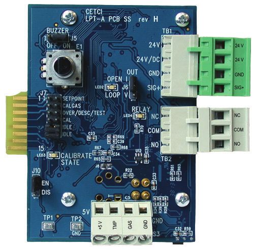
LPT-A - Operation Manual Rev. H | 2021.09
TABLE OF CONTENTS
1 POLICIES .......................................................................................................... 5
1.1 Important Note ................................................................................................5
1.2 Warranty Policy ................................................................................................6
1.3 Service Policy ...................................................................................................6
1.4 Copyrights ........................................................................................................7
1.5 Disclaimer ........................................................................................................7
1.6 Revisions ..........................................................................................................8
2 INTRODUCTION ............................................................................................. 9
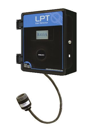
2.1 General Description..........................................................................................9
2.2 Key Features...................................................................................................10
3 INSTRUMENT SPECIFICATIONS .................................................................10
3.1 Technical Specifications..................................................................................10
3.2 Internal Gas Sensor Types ...............................................................................14
3.3 ESH-A Remote Sensor Types ...........................................................................16
3.4 Enclosure Dimensions ....................................................................................17
4 INSTRUMENT FEATURES.............................................................................18
4.1 Exterior Enclosure ..........................................................................................18
4.2 Interior System Layout ...................................................................................19
4.2.1 Electrochemical Sensor Board .........................................................................19
4.2.2 Solid State (Internal) Sensor Board .................................................................20
4.2.3 Solid State (Remote) Sensor Board..................................................................21
5 INSTALLATION ..............................................................................................22
5.1 Special Considerations for Different Types of Sensors .....................................23
5.2 Calibration Extending Firmware (CEF) and Sensor Aging................................25
2 © 2021 All rights reserved. Data subject to change without notice.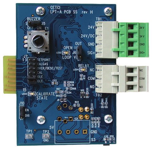
Rev. H | 2021.09                                                                                              LPT-A - Operation Manual

         5.3 General Safety Warnings ................................................................................25
         5.4 Protection Against Electrical Risks..................................................................25
         5.5 Protection Against Mechanical Risks ..............................................................26
         5.6 Mounting the Transmitter ..............................................................................27
                5.6.1 Wet Environment Considerations ....................................................................27
                5.6.2 EMI and RF Interference Considerations ..........................................................28
                5.6.3 Mounting Height (Sensor Dependent) ............................................................28
         5.7 Enclosure Mounting Components ..................................................................29
                5.7.1 Enclosure Base ................................................................................................29
                5.7.2 Enclosure Bottom ............................................................................................30
         5.8 Wiring Connections ........................................................................................30
                5.8.1 Power Connection ...........................................................................................31
                5.8.2 Relay Connection ............................................................................................32
                5.8.3 Wiring LPT-A to Remote ESH Sensor (dongle style) .........................................33
                5.8.4 Wiring LPT-A to ESH-A Remote Sensor ............................................................34
                5.8.5 Wire Gauge vs Run Length...............................................................................35
                5.8.6 Open Loop .......................................................................................................36
6 SYSTEM OPERATION & CONFIGURATION ................................................37
         6.1 Power Up and Warm-up .................................................................................37
         6.2 Display Select.................................................................................................38
         6.3 Enable / Disable the Buzzer ............................................................................39
         6.4 Selecting the Output Signal ...........................................................................39
         6.5 Fault Detection...............................................................................................40
         6.6 Test Functions ................................................................................................40
         6.7 Relay Operation / Setting the “Alarm” Level ...................................................41

© 2021 All rights reserved. Data subject to change without notice.                                                                     3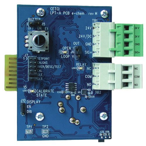
LPT-A - Operation Manual                                                                                                    Rev. H | 2021.09

7 CALIBRATION................................................................................................43
         7.1 Calibration Specifications ...............................................................................43
                7.1.1 Gas ..................................................................................................................43
                7.1.2 Regulators & Flow ...........................................................................................44
                7.1.3 Adapters..........................................................................................................44
                7.1.4 Humidifier.......................................................................................................44
                7.1.5 Calibration Frequency .....................................................................................44
                7.1.6 Gas Testing Frequency (Bump Testing) ............................................................45
                7.1.7 Sticky Gases.....................................................................................................45
                7.1.8 Non-Intrusive Calibration ................................................................................45
         7.2 Calibrating the Internal Sensor ......................................................................46
         7.3 Troubleshooting Calibration ...........................................................................51
                7.3.1 How to Reset the LPT-A to Factory Calibration Settings...................................53
         7.4 Calibrating an ESH-A Remote Sensor Connected to an LPT-A .........................53
                7.4.1 Zero and Span Calibration of a Responsive ESH-A Remote Sensor ...................54
                7.4.2 Zero Calibration of a New or Replacement ESH-A Remote Sensor....................54
         7.5 Calibrating an Oxygen Sensor ........................................................................55
8 ACCESSORIES ...............................................................................................59
         8.1 Splash Guard (Option -S)................................................................................59
         8.2 Calibration Adapter Clip “Cal Clip”...................................................................60
         8.3 Magnetic Wand ..............................................................................................60
         8.4 Metal Protective Guards .................................................................................61
         8.5 Calibration Kit ................................................................................................61
9 MAINTENANCE .............................................................................................62
10 TROUBLE SHOOTING ................................................................................62

4                                                                     © 2021 All rights reserved. Data subject to change without notice.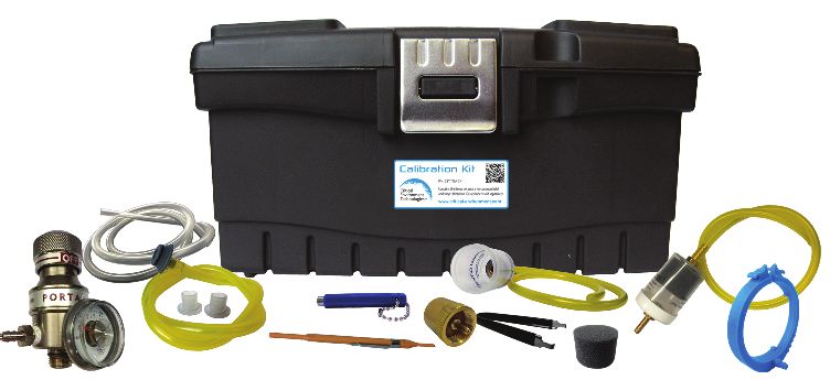
Rev. H | 2021.09                                                                   LPT-A - Operation Manual

1 POLICIES
1.1 Important Note
Read and understand this manual prior to using this instrument. Carefully read the warranty policy,
service policy, notices, disclaimers and revisions on the following pages.

This product must be installed by a qualified electrician or factory trained technician and according
to instructions indicated in this manual. This instrument should be inspected and calibrated
regularly by a qualified and trained technician. For more information, refer to Section 7 Calibration
and Section 9 Maintenance of this manual.

This instrument has not been designed to be intrinsically safe. For your safety, do not use it in
classified hazardous areas (explosion-rated environments).

INSTRUMENT SERIAL NUMBER:

______________________________________________________

PURCHASE DATE:

______________________________________________________

PURCHASED FROM:

______________________________________________________

© 2021 All rights reserved. Data subject to change without notice.                                       5

LPT-A - Operation Manual                                                                             Rev. H | 2021.09

1.2 Warranty Policy
Critical Environment Technologies Canada Inc. warrants the products we manufacture (excluding
sensors, battery packs, batteries, pumps, and filters) to be free from defects in materials and
workmanship for a period of two years from the date of purchase from our facility. As a reminder,
sensors are consumable items and once they leave our factory, we cannot reuse or resell them.
As such, all sensor sales are final. Should the sensor itself be faulty, there is a one-year pro-rated
warranty that would apply from the date of purchase from our facility.

The warranty status may be affected if the instrument has not been used and maintained as per
the instructions in the manual or has been abused, damaged, or modified in any way. The product
is only to be used for the purposes stated in the manual. Critical Environment Technologies is not
liable for auxiliary interfaced equipment or consequential damage.

All returned goods must be pre-authorized by obtaining a Returned Merchandise Authorization
(RMA) number. All goods must be shipped to Critical Environment Technologies freight prepaid.
Contact the manufacturer for an RMA number and procedures required for product transport.

Due to ongoing research, development, and product testing, the manufacturer reserves the right to
change specifications without notice. The information contained herein is based on data considered
accurate. However, no warranty is expressed or implied regarding the accuracy of this data.

1.3 Service Policy
CETCI maintains an instrument service facility at the factory. Some CETCI distributors / agents may
also have repair facilities; however, CETCI assumes no liability for service performed by anyone
other than CETCI personnel.

Repairs are warranted for 90 days after date of shipment (sensors have individual warranties).
Should your instrument require non-warranty repair, you may contact the distributor from whom it
was purchased or you may contact CETCI directly.
6                                                   © 2021 All rights reserved. Data subject to change without notice.
Rev. H | 2021.09                                                                   LPT-A - Operation Manual

Prior to shipping equipment to CETCI, contact our office for an RMA #. All returned goods must be
accompanied with an RMA number.

If CETCI is to do the repair work, you may send the instrument, prepaid, to:
    Attention: RMA# _______________
    Critical Environment Technologies Canada Inc.
    Unit 145, 7391 Vantage Way
    Delta, BC, V4G 1M3

You must include your Returned Merchandise Authorization (RMA) number, address, telephone
number, contact name, shipping / billing information, and a description of the defect as you
perceive it. You will be contacted with a cost estimate for expected repairs, prior to the performance
of any service work. Pack the equipment well (in its original packing if possible), as we cannot
be held responsible for any damage incurred during shipping to our facility. All incurred shipping
charges, duties and taxes are your responsibility.

For liability reasons, CETCI has a policy of performing all needed repairs to restore the instrument to
full operating condition.

1.4 Copyrights
This manual is subject to copyright protection; all rights are reserved. Under international and
domestic copyright laws, this manual may not be copied or translated, in whole or in part, in any
manner or format, without the written permission of CETCI.

1.5 Disclaimer
Under no circumstances will CETCI be liable for any claims, losses or damages resulting from or
arising out of the repair or modification of this equipment by a party other than CETCI service
technicians, or by operation or use of the equipment other than in accordance with the printed

© 2021 All rights reserved. Data subject to change without notice.                                       7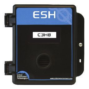
LPT-A - Operation Manual                                                                             Rev. H | 2021.09

instructions contained within this manual or if the equipment has been improperly maintained or
subjected to neglect or accident. Any of the forgoing will void the warranty.

Under most local electrical codes, low voltage wires cannot be run within the same conduit as line
voltage wires. It is CETCI policy that all wiring of our products meet this requirement.

It is CETCI policy that all wiring be within properly grounded (earth or safety) conduit.

1.6 Revisions
This manual was written and published by CETCI. The manufacturer makes no warranty or
representation, expressed or implied including any warranty of merchantability or fitness for
purpose, with respect to this manual.

All information contained in this manual is believed to be true and accurate at the time of printing.
However, as part of its continuing efforts to improve its products and their documentation, the
manufacturer reserves the right to make changes at any time without notice. Revised copies of this
manual can be obtained by contacting CETCI or visiting www.critical-environment.com.

Should you detect any error or omission in this manual, please contact CETCI at the following
address:

Critical Environment Technologies Canada Inc.
Unit 145, 7391 Vantage Way, Delta, BC, V4G 1M3, Canada
Toll Free:      +1.877.940.8741
Telephone: +1.604.940.8741
Email:          marketing@cetci.com
Website:        www.critical-environment.com

8                                                   © 2021 All rights reserved. Data subject to change without notice.
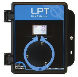
Rev. H | 2021.09                                                                 LPT-A - Operation Manual

In no event will CETCI, its officers or employees be liable for any direct, special, incidental or
consequential damages resulting from any defect in any manual, even if advised of the possibility
of such damages.

2 INTRODUCTION
2.1 General Description
Thank you for purchasing our LPT-A Analog Transmitter.

The LPT-A transmitter is a single sensor, analog transmitter available with a wide range of sensors
and sensor types of continuous monitoring of gases or oxygen in non-hazardous (non-explosion
rated) environments such as commercial HVAC and light industrial applications.

Operating as an analog transmitter or a stand-alone fixed system, the LPT-A offers a back lit LCD
display, an internal audible alarm, one dry relay contact, a jumper selectable 4-20 mA or 0 - 10 VDC
analog output signal, 3-wire VDC or 4-wire VAC power, a thermal resetting fuse and temperature
compensation all in a RoHS compliant package. It comes in a standard with a water / dust tight,
corrosion resistant ABS / polycarbonate enclosure with a hinged, secured door. With the optional
splash guard installed, the enclosure is IP54 rated and ideal for use in water spray or washdown
applications.

LPT-A transmitter is available with internal or remote sensor options. All LPT-A transmitters operate
by diffusion. The sensors utilized in this device are accurate enough to measure to Occupational
Health & Safety (OHS) hazardous levels for toxic gases.

If after reading through the manual, you have any questions, please do not hesitate to contact our
Technical Service Department for technical support.

© 2021 All rights reserved. Data subject to change without notice.                                     9

LPT-A - Operation Manual                                                                              Rev. H | 2021.09

2.2 Key Features
      •   Single channel
      •   Wide range of internal sensor types including electrochemical, solid state and TVOC
      •   Remote combustible and PID sensor options
      •   Graphic LCD display (user selectable function)
      •   Audible alarm
      •   3-wire VDC or 4-wire VAC power
      •   24 volt DC or AC power (nominal)
      •   Linear 4 - 20 mA or 0 - 10 volt output signal
      •   1 dry contact relay, 30 volt 2 amps maximum
      •   Standard water / dust tight, corrosion resistant enclosure (drip proof). With optional splash
          guard installed, the enclosure is IP54 rated.
      •   Copper coated interior to reduce RF interference
      •   RoHS compliant circuit boards
      •   Includes sensor Calibration Extending Firmware (CEF) for some electrochemical sensors
      •   Auto resetting fuse

3 INSTRUMENT SPECIFICATIONS
3.1 Technical Specifications
  MECHANICAL
                                  ABS / Polycarbonate, IP54 rating with splash guard installed.
  Enclosure
                                  Copper coated interior to reduce RF interference.
  Weight                          400 g (14 oz)

10                                                   © 2021 All rights reserved. Data subject to change without notice.
Rev. H | 2021.09 LPT-A - Operation Manual
Size 127 mm x 127 mm x 53.34 mm (5.0 in x 5.0 in x 2.1 in )
ELECTRICAL
Power Requirement
3-wire mode 16 - 30 VDC, 3 W, Class 2
4-wire mode 12 - 27 VAC, 50-60 Hz, 3 VA, Class 2
Use Class 2 transformer. See Section 5.8 Wiring Connections.
Current Draw 125 mA @ 24 VDC
VDC (or ground referenced AC) three conductor shielded 18 awg
(or larger) stranded within conduit
Wiring
VAC four conductor shielded 18 awg stranded within conduit
(refer to Section 5.8.5 Wire Gauge vs. Run Length)
Fuses Automatic resetting thermal
USER INTERFACE
Graphic LCD, grey border. Text prompting for calibration operation
Display and fault indications. Installer configurable to suppress all other
displays.
Using the magnetic wand to initiate calibration without opening
Magnetic Sensors
enclosure.
Audible Alarm Standard internal buzzer, rated 90 dB @ 10 cm, enable/disable
© 2021 All rights reserved. Data subject to change without notice. 11LPT-A - Operation Manual Rev. H | 2021.09
INPUTS / OUTPUTS
Linear 4 - 20 mA
Maximum 216 Ω load (wiring plus termination resistor) @ 12 VDC
Maximum 316 Ω load (wiring plus termination resistor) @ 12 VAC
Outputs
Voltage 0 - 10 volt
Minimum 1k ohm load
Relay One SPDT dry contact relay, rated 2A @ 30V maximum
ENVIRONMENTAL
-20°C to 40°C (-4°F to 104°F)
NOTE: Low temperature option available to -40°C (-40°F) (Sensor
Operating Temperature dependent, some extremely cold applications may require a small
internal silicone heater to maintain temperature stability for sensor.
Contact CETCI for details and pricing.)
Operating Humidity 15 - 90% RH non-condensing
12 © 2021 All rights reserved. Data subject to change without notice.Rev. H | 2021.09 LPT-A - Operation Manual
CERTIFICATIONS
Model: LPT-A-XXX
S/N: LPTAE1601H00374
Rating: 16-30 VDC, 3W, Class 2
12-27 VAC, 50-60 Hz 3VA, Class 2
CERTIFIED FOR ELECTRIC SHOCK & ELECTRICAL FIRE HAZARD ONLY. LA CERTIFICATION ACNOR
COUVRE UNIQUEMENT LES RISQUES DE CHOC ELECTRIQUE ET D’INCENDIE D’ORIGINE ELECTRIQUE.
Conforms to: CSA-C22.2 No. 205-M1983 (R2009), UL508 (Edition 17):2007
Conforms to: EMC Directive 2004/108/EC, EN 50270:2006, Type 1, EN61010
Conforms to: FCC. This device complies with Part 15 of the FCC Rules. Operation is subject to
the following two conditions: (1) This device may not cause harmful interference, and (2) this
device must accept any interference received, including interference that may cause undesired
operation.
© 2021 All rights reserved. Data subject to change without notice. 13LPT-A - Operation Manual Rev. H | 2021.09
3.2 Internal Gas Sensor Types
Internal Electrochemical
Part Number Range Lifespan
Sensors
Ammonia (NH3) LPT-A-NH3 0 - 500 ppm ~2 years
Carbon Monoxide (CO) LPT-A-COA 0 - 200 ppm ~3 years
Carbon Monoxide (CO) LPT-A-COB 0 - 200 ppm ~6 years
Chlorine (Cl2) LPT-A-CL2 0 - 5.0 ppm ~3 years
Chlorine Dioxide (ClO2) LPT-A-CLO2 0 - 1.0 ppm ~2 years
Ethylene (C2H4) LPT-A-C2H4 0 - 200 ppm ~2 years
Ethylene Oxide (C2H4O) LPT-A-EETO 0 - 20 ppm ~2 years
Fluorine (F2) LPT-A-F2 0 - 1.0 ppm ~1 - 2 years
Formaldehyde (CH2O) LPT-A-CH2O 0 - 5.0 ppm ~2 years
Hydrogen (H2) LPT-A-EH2 0 - 2,000 ppm ~2 years
Hydrogen Chloride (HCl) LPT-A-HCL 0 - 30 ppm ~2 years
Hydrogen Cyanide (HCN) LPT-A-HCN 0 - 30 ppm ~2 years
Hydrogen Fluoride (HF) LPT-A-HF 0 - 10.0 ppm ~1 - 2 years
Hydrogen Sulphide (H2S) LPT-A-H2S 0 - 50 ppm ~2 years
Hydrogen Sulphide (H2S) LPT-A-H2SB 0 - 50 ppm ~5 years
Nitric Oxide (NO) LPT-A-NO 0 - 100 ppm ~2 years
Nitrogen Dioxide (NO2) LPT-A-NO2A 0 - 10 ppm ~3 years
14 © 2021 All rights reserved. Data subject to change without notice.Rev. H | 2021.09 LPT-A - Operation Manual Internal Electrochemical Part Number Range Lifespan Sensors continued... Nitrogen Dioxide (NO2) LPT-A-NO2B 0 - 10 ppm ~6 years Oxygen (O2) LPT-A-O2 0 - 25% Vol ~3 years Ozone (O3) LPT-A-O3 0 - 1.0 ppm ~2 years Phosphine (PH3) LPT-A-PH3 0 - 1.0 ppm ~2 years Silane (SiH4) LPT-A-SIH4 0 - 20 ppm ~2 years Sulphur Dioxide (SO2) LPT-A-SO2 0 - 20 ppm ~2 years Internal Solid State Sensors Part Number Range Lifespan Refrigerant (R22) LPT-A-SR22 0 - 2,000 ppm ~5 years Refrigerant (R134A) LPT-A-SR134A 0 - 2,000 ppm ~5 years Refrigerant (R402A) LPT-A-SR402A 0 - 2,000 ppm ~5 years Refrigerant (R404A) LPT-A-SR404A 0 - 2,000 ppm ~5 years Refrigerant (R407C) LPT-A-SR407C 0 - 2,000 ppm ~5 years Refrigerant (R410A) LPT-A-SR410A 0 - 2,000 ppm ~5 years Refrigerant (R422D) LPT-A-SR422D 0 - 2,000 ppm ~5 years Refrigerant (R438A) LPT-A-SR438A 0 - 2,000 ppm ~5 years Refrigerant (R438A) LPT-A-SR438A 0 - 2,000 ppm ~5 years Refrigerant (R507A) LPT-A-SR507A 0 - 2,000 ppm ~5 years © 2021 All rights reserved. Data subject to change without notice. 15
LPT-A - Operation Manual                                                                      Rev. H | 2021.09

  Refrigerant (R514A)            LPT-A-SR514A             0 - 2,000 ppm              ~5 years
  TVOC (Isobutylene)             LPT-A-STVOC              0 - 500 ppm                ~5 years

  Internal Catalytic             Part Number              Range                      Lifespan
  (Combustible) Sensors
  Hydrogen (H2)                  LPT-A-CH2-100            0 - 100% LEL               ~5 years
  Methane (CH4)                  LPT-A-CCH4-100           0 - 100% LEL               ~5 years
  Propane (C3H8)                 LPT-A-CC3H8-100          0 - 100% LEL               ~5 years

3.3 ESH-A Remote Sensor Gas Types
  ESH-A Remote Sensors - Catalytic (Combustible)
  Hydrogen (H2)                  ESH-A-CH2-100            0 - 100% LEL               ~5 years
  Methane (CH4)                  ESH-A-CCH4-100           0 - 100% LEL               ~5 years
  Propane (C3H8)                 ESH-A-CC3H8-100          0 - 100% LEL               ~5 years

  ESH-A Remote Sensors - TVOC PID
  TVOC PID                       ESH-A-SPL                0 - 30 ppm                 usage / application
  TVOC PID                       ESH-A-SPH                0 - 300 ppm                dependent

16                                           © 2021 All rights reserved. Data subject to change without notice.
Rev. H | 2021.09                                                                          LPT-A - Operation Manual

3.4 Enclosure Dimensions
                               127 mm (5.0 in )                                         61 mm (2.4 in )

                                                                     127 mm (5.0 in )

Above dimensions are shown with optional splash guard. Without splash guard, thickness is
53.34 mm (2.1 in). The area required for enclosure door to be open 90 degrees is 178 mm (7 in) or
254 mm (10 in) for fully open. With the splash guard, the enclosure has an IP54 rating.

NOTE: During calibration, the sensor response time will be slower with a splash guard installed.

NOTE: The standard splash guard (Option -S) is optional for protecting non sticky gas sensors
in wash down applications. For sticky gas sensors such as Chlorine (Cl2), Chlorine Dioxide (ClO2),
Hydrogen Chloride (HCL), Hydrogen Cyanide (HCN), Hydrogen Fluoride (HF), Ozone (O3) and
Phosphine (PH3) order the sticky gas splash guard Option -SN).

© 2021 All rights reserved. Data subject to change without notice.                                             17
LPT-A - Operation Manual Rev. H | 2021.09
4 INSTRUMENT FEATURES
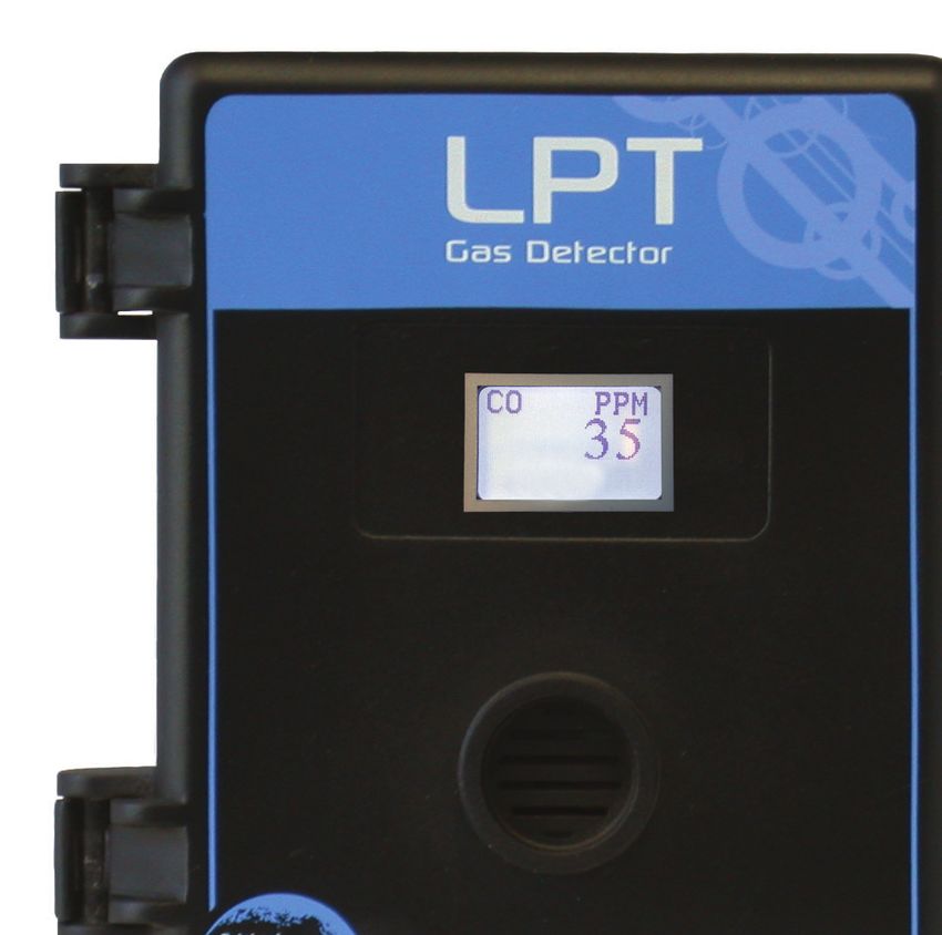
4.1 Exterior Enclosure
NUMBER FEATURE FUNCTION
Door Hinge Secures door
Display with gray border Indicates transmitter operation
Door Screw Secures door
Sensor Opening Allows gas diffusion into sensor
Padlock Opening For security padlock
Magnetic Calibration Trigger Point To enter calibration
18 © 2021 All rights reserved. Data subject to change without notice.Rev. H | 2021.09 LPT-A - Operation Manual
4.2 Interior System Layout
Depending on the type of sensor the LPT-A is configured with, one of three circuit boards will be
installed inside.
4.2.1 Electrochemical Sensor Board
© 2021 All rights reserved. Data subject to change without notice. 19LPT-A - Operation Manual Rev. H | 2021.09
4.2.2 Solid State (Internal) Sensor Board
20 © 2021 All rights reserved. Data subject to change without notice.Rev. H | 2021.09 LPT-A - Operation Manual
4.2.3 Solid State (Remote) Sensor Board
11
TMP
GND
SNS
V+
NUMBER FEATURE FUNCTION
J5 Buzzer Enable Enables / disables the buzzer.
Rotary Encoder Sets calibration values, etc. with the jumpers.
© 2021 All rights reserved. Data subject to change without notice. 21LPT-A - Operation Manual Rev. H | 2021.09
Lights if there is no connection for current output
Open Loop LED
(always lit in voltage output mode).
J7 Jumper Bank For calibration & test functions.
Calibrate State LED Further prompting for calibration operation.
Enables / disables the display of the measured gas
J10 Display Enable
level.
Test Points: TP1 & TP2 For measuring voltage output.
TB1 Wiring Terminal Pluggable terminal for Power & signal output.
Output Select Select either current or voltage output.
Indicates (when on) that the gas level is above the
Relay LED
trip point (the relay will indicate alarm level).
TB2 Relay Terminal Pluggable terminal for relay connections.
11 Remote Sensor Terminal Terminal for remote sensor connections.
5 INSTALLATION
The sensor in the LPT-A goes through a burn in period at our factory prior to shipiping so it is ready
for operation upon arrival. If you install the LPT-A when it arrives, most sensors will not require a
long warm up period (about 5 minutes for Ammonia and Nitrogen dioxide, 2 minutes for the other
gases, except Oxygen which is a minimum of 2 hours). If the device is not installed within two
weeks of delivery, the sensor may require a longer warm up time to stabilize (approximately 48
hours) and provide accurate readings.
22 © 2021 All rights reserved. Data subject to change without notice.Rev. H | 2021.09 LPT-A - Operation Manual
NOTE: CETCI suggests that upon power-up, all sensors be left to warm up for 24 hours
prior to considering the gas readings to be accurate.
NOTE: All sensors are calibrated in the factory and do not require calibration at the time
of a routine installation.
NOTE: Temperature affects calibration. It is important to ensure the gas is at the appropriate
temperature during calibration. If the sensor is being used in an extreme temperature range,
calibration should be done in that same temperature range.
5.1 Special Considerations for Different Types of
Sensors
After installing an LPT-A with an Oxygen sensor, leave it to warm up for at least 2 hours before
looking at the readings. If after at least 2 hours, the gas reading is not 20.9%, you should do a
respan.
Trigger the Respan by:
• Moving the internal jumper from J7 IDLE position to the CAL position.
• The LPT-A will use the last four seconds of gas data to determine the Oxygen span gas level.
If the Span is successful, the LPT-A will show the following message: SPAN ACCEPTED.
• Remove the jumper from CAL and put it back on IDLE.
• The respan process is complete. DO NOT proceed with flowing nitrogen.
If the Span was not successful:
• If spanning times out without an acceptable value the display will show ‘SPAN FAILED!
RECALIBRATE’.
© 2021 All rights reserved. Data subject to change without notice. 23LPT-A - Operation Manual Rev. H | 2021.09
• The 4-20 mA output will signal the failure with 0 mA (0 -10 volt will be 0 volt). This condition
can only be resolved by a successful calibration.
• If the calculated sensitivity of the sensor is out of range the display will show ‘SPAN FAILED!
RECALIBRATE’ indicating the sensor cannot be calibrated. You can try to recalibrate, starting
from Step 2, to confirm the procedure was followed correctly and this may correct the fault.
• If span fails repeatedly the sensor has either aged beyond its useful life or has otherwise
failed, please contact our Technical Service Department at help@cetci.com.
After a substantial warm up period, an Ethylene Oxide sensor should be zeroed on site if the
ambient temperature is above 22°C (71.6°F). This particular sensor has a drift factor that can be as
much as 1 ppm if the temperature rises to 25°C (77°F). With the low set point you could experience
false alarms.
For an R11 refrigerant sensor, allow 30 minutes after power up before considering the LPT-A’s
readings valid. The sensor’s response to R11 refrigerant and to humidity levels can affect the
readings of the LPT-A and can take up to 30 minutes after power up to recover and stabilize.
During calibration, when flowing span gas on an Ammonia sensor, if the reading climbs higher than
the calibration point after applying gas for 3 minutes, use that reading as the calibration point. It
should be around 300 ppm.
Ozone sensors are reactive to temperature changes and will drift.
Silicone, lead and chlorinated hydrocarbon vapours can poison catalytic sensors.
A bump test will help you determine if a sensor requires calibration. If the sensor still does not
respond as it should after a successful calibration, it probably requires replacing.
24 © 2021 All rights reserved. Data subject to change without notice.Rev. H | 2021.09 LPT-A - Operation Manual 5.2 Calibration Extending Firmware (CEF) and Sensor Aging Some LPT-A systems with certain electrochemical sensors have been programmed with our Calibration Extending Firmware (CEF). This firmware takes into consideration the aging of the sensors so that less frequent calibrations are acceptable in less-critical applications such as parking garages. The system tracks the age of the sensor and automatically compensates for the reduced output of the sensor as it ages. 5.3 General Safety Warnings The LPT-A is intended for indoor use, permanently mounted at a height that is appropriate for the type of gas being monitored. See Section 5.6 Mounting the Transmitter. The LPT-A should be protected from extreme weather conditions. The LPT-A requires no assembly and virtually no maintenance other than regular calibration of the integral and/or remote sensors and ensuring that excess water or dust is not somehow entering the enclosure and physically damaging the circuit board or internal components. There are no serviceable elements other than the calibration instructions outlined in this manual. There are no replaceable components except the sensors. 5.4 Protection Against Electrical Risks Disconnect all power before servicing. There may be multiple power sources. Power supply may have a building installed circuit breaker / switch that is suitably located and easy to access when servicing is required and should be labelled as LPT-A supply (disconnecting power to the LPT-A). Appropriate markings should be visible at the circuit breaker / switch that is supplying power to the LPT-A. This device may interfere with pacemakers. Modern pacemakers have built-in features to protect © 2021 All rights reserved. Data subject to change without notice. 25
LPT-A - Operation Manual                                                                            Rev. H | 2021.09

them from most types of interference produced by other electrical devices you might encounter in
your daily routine. If you a have a pacemaker, follow your healthcare provider’s instructions about
being around this type of equipment.

5.5 Protection Against Mechanical Risks
The door of the enclosure can be removed if absolutely necessary to facilitate installation of the
base but it is not recommended on this version. Extreme care and caution must be exercised
when removing the door to avoid damaging the hinges. The door should only be removed when
absolutely required. Any damage occurring from door removal procedure will not be covered under
warranty.

Simply grasp the door with one hand, being careful not to make contact with any of the internal
components (circuit board), grasp the base with your other hand. Tug on the base and pull straight
apart. DO NOT TWIST. The section of the hinges located on the base should “snap” apart from the
part of the hinges located on the door.

After installation, simply locate the lid hinges over the installed base hinges and pull toward you.
The hinges should easily “snap” back into place.

The enclosure has one screw securing the door to the base for electrical safety and provides an
opening to allow the user to apply a padlock or tie wrap if they desire the transmitter to be locked.
Refer to Section 4.1 Exterior Enclosure.

Be aware that the hinged door that could potentially pinch fingers and the sharp edges and/or
jumper pins on the board could potentially prick or cut fingers if not handled carefully.

26                                                 © 2021 All rights reserved. Data subject to change without notice.
Rev. H | 2021.09                                                                LPT-A - Operation Manual

5.6 Mounting the Transmitter
The LPT-A should be mounted on a flat vertical surface using the four 4.4 mm (0.175”) diameter
mounting holes provided to maintain water tight status. Care should be taken to ensure that the
face of the LPT-A is not obstructed in order to maximize the sensor’s exposure to the environment
being monitored.

Two 12.7 mm (½ in) conduit entry points are provided in the enclosure. Both are located in the
enclosure base. One in the rear of the base and one on the bottom edge of the base. See Section 5.7
Enclosure Mounting Components.

The clearance from the PCA to the base enclosure is 12.7 mm (½ in). Do not use a conduit
connector that has more than 12.7 mm (½ in) of thread length.

NOTE: When mounting the enclosure, allow enough room to allow the end user to open the door
fully to access the internal adjustments.

5.6.1 Wet Environment Considerations
If the LPT-A is to be installed in a potential hose-down application or any application whereby
liquid could be directed towards the sensor opening, the LPT (depending on gas sensor type)
should be ordered with a factory installed splash guard (Option -S) or a separate metal guard with
a factory installed splash cover (p/n: SCS-8000-RSG-WSG). Standard gas sensors like CO, NO2 and O2
can be protected with the factory installed splash guard. Sticky gas sensors like Cl2 and O3 do not
work with a splash guard, but can be protected by a metal guard with a splash cover.

If used in a wet or wash down application, the conduit hub entering the LPT-A enclosure
must be liquid tight type. Any water or physical damage to the transmitter that occurs from the
installer drilling their own installation holes will not be covered under warranty.

© 2021 All rights reserved. Data subject to change without notice.                                   27
LPT-A - Operation Manual                                                                            Rev. H | 2021.09

5.6.2 EMI and RF Interference Considerations
All electronic devices are susceptible to EMI (Electromagnetic Interference) and RFI (Radio
Frequency Interference). Our detectors have been designed to reduce the effects of these
interferences and we meet CSA FCC and CE requirements for these type of devices. However, there
are still circumstances and levels of interference that may cause our equipment to respond to these
interferences and cause them to react as if there has been gas detected.

There are some installation procedures that will reduce the likelihood of getting faulty readings:
      1. Locate the detectors and controllers out of the way from normal foot traffic and high
         energy equipment.
      2. Confirm the devices are properly grounded using conduit and shielded cabling.
      3. Inform operators and technical staff working in the surrounding area to be aware of these
         possible conditions and that two way radios, Bluetooth enabled devices, cell phones and
         other electrical equipment may interfere with the response of the gas detectors.

5.6.3 Mounting Height (Sensor Dependent)
The sensor mounting height depends on the density of the gas relative to air. Heavier than air gases
should be detected 6 in / 15 cm from the floor, lighter than air gas sensors should be placed on or
near the ceiling, and gases which have a density close to that of air should have sensors installed
in the “breathing zone” 4 - 6 ft / 1.2 - 1.8 m from the floor. The breathing zone refers to the area
4 - 6 ft / 1.2 - 1.8 m from the floor, where most human breathing takes place. This is a good default
location for sensors, as many gases are often well dispersed in air.

              GAS                APPLICATIONS / TYPES                SUGGESTED MOUNTING HEIGHT
  Carbon Monoxide (CO)        Gas engine exhaust                            4 - 6 ft above the floor
  Nitrogen Dioxide (NO2)      Diesel engine exhaust                       1.2 - 1.8 m above the floor

28                                                 © 2021 All rights reserved. Data subject to change without notice.
Rev. H | 2021.09 LPT-A - Operation Manual
Commercial ice rinks
Ammonia (NH3) Near the ceiling
Compressor rooms
Chlorine (Cl2) 6 in above the floor
Commercial swimming pools
Ozone (O3) 15 cm above the floor
5.7 Enclosure Mounting Components
5.7.1 Enclosure Base
NUMBER FEATURE
Door Hinge
© 2021 All rights reserved. Data subject to change without notice. 29LPT-A - Operation Manual Rev. H | 2021.09
1/2” Conduit Entry Knockout
Mounting Holes
5.7.2 Enclosure Bottom
NUMBER FEATURE
Door Hinge
1/2” Conduit Entry Knockout
5.8 Wiring Connections
The LPT-A analog transmitter is a low voltage powered device. Any application of operating
voltages higher than indicated in the specification may result in damage. Double check wiring
connections prior to powering the transmitter. Damage from incorrect wiring connections or from
too much voltage applied is not covered under warranty.
All wiring should be run in EMT (or better) conduit properly earth grounded. Signal output and
supply should be in shielded cable. The cable shield should be connected to earth ground at the
controller/power supply that is providing power for the LPT-A.
30 © 2021 All rights reserved. Data subject to change without notice.Rev. H | 2021.09 LPT-A - Operation Manual 5.8.1 Power Connection If the installer is powering the LPT-A with four wire 24 VAC, the VAC wires should be connected to the terminal “one” (AC) and terminal “two” (AC / DC), from the top down. The signal return should be connected to terminal “three” (GND). The “signal” (4 - 20 mA or 0 - 10 volt) wire is always connected to terminal “four”. Wiring Example: 4-Wire If the installer is powering the LPT-A with three wire 24 VDC or ground referenced AC, the “positive” wire should be connected to terminal “two” (AC / DC) and the negative wire should be connected to terminal “three” (GND). The “signal” (4 - 20 mA or 0 - 10 volt) wire is always connected to terminal “four”. Wiring Example: 3-Wire NOTE: WARRANTY VOID IF SOLID-CORE WIRE IS USED AT THE WIRING TERMINAL STRIP. When using solid core wiring for distribution (in the conduit), use stranded wire pigtails 18 AWG within the enclosure to connect to the circuit board. The rigidity of solid-core wire can pull a © 2021 All rights reserved. Data subject to change without notice. 31
LPT-A - Operation Manual                                                                             Rev. H | 2021.09

soldered terminal strip completely off a circuit board and this will not be covered under warranty.

System power: The main wiring terminal strip on the LPT circuit board can be unplugged for
easier wiring installation. Grasp the two sides of the terminal strip and pull sideways. Device must
be used with rated equipment. External power to LPT-A must be supplied by a Class 2 or better
transformer.

5.8.2 Relay Wiring Connection
The LPT-A is designed to be fail-safe. Equipment to be controlled by the relay should be wired to
the “NC” (Normally closed) and “COM” (Common) terminals. With this wiring, the connection will
be open under normal, low gas concentration conditions. When the gas concentration rises to the
configured alarm point or if there is a power failure, the connection relay will close. The relay coils
are normally energized in a non-alarm state for failsafe operation.

The relay in the LPT-A is intended for triggering horn/strobe equipment, not ventilation control. If
ventilation control is required, contact our Technical Service Department.

Wiring Example: Relay

32                                                  © 2021 All rights reserved. Data subject to change without notice.
Rev. H | 2021.09                                                                          LPT-A - Operation Manual

5.8.3 Wiring from LPT-A to Remote ESH (dongle style) Sensor for Hotel
Room Air Conditioning Applications
Four-conductor, 16-18 awg stranded shielded cable is required for the remote dongle style sensor
wiring. This wiring should be run in a conduit, separate from the signal output, and should not
exceed 50 feet. The voltage at the remote sensor (Red V+ to Black GND) should be 5 VDC ± 2%. If
this voltage is not met after installation, the wrong gauge wire may have been used or the wiring
run is too long.

                                                The solid state sensor breathes      Wiring:
                                                   through these openings.           • Red (V+)
                                                                                     • Yellow (Signal)
                                                                                     • Black (Ground)
                                                                                     • White (Temperature)

Wiring Example: Remote ESH (dongle style) Sensor
                                                 RED
                                V+
                                                WHITE
                                TMP
                                              YELLOW
                                SNS
                                GND            BLACK

                                LPT-A                                Remote Sensor

The maximum length of wire between the ESH Remote Sensor (dongle style) and the
transmitter should not exceed 50 ft (15 m).

© 2021 All rights reserved. Data subject to change without notice.                                             33
LPT-A - Operation Manual Rev. H | 2021.09 5.8.4 Wiring from LPT-A to an ESH-A Remote Sensor Each ESH-A is given the same serial number as the device it is being connected to. Make sure to connect the ESH-A to the LPT-A that has the same serial number or the system won’t work. Four-conductor, 16-18 awg stranded shielded cable is required for the ESH-A Remote Sensor wiring. This wiring should be run in a conduit, separate from the LPT-A’s wiring, and should not exceed 200 feet. NOTE: WARRANTY VOID IF SOLID-CORE WIRE IS USED AT THE WIRING TERMINAL STRIP. When using solid core wiring for distribution (in the conduit), use stranded wire pigtails 18 AWG within the enclosure to connect to the circuit board. The rigidity of solid-core wire can pull a soldered terminal strip completely off a circuit board and this will not be covered under warranty. The wiring terminal strips on the ESH-A Remote Sensor circuit board are mounted on a 30 degree angle, making the wiring connections easier to install. Device must be used with rated equipment. External power to the ESH-A is supplied by the controller or transmitter it is connected to. Wiring Example: ESH-A Remote Sensor 34 © 2021 All rights reserved. Data subject to change without notice.
Rev. H | 2021.09                                                                         LPT-A - Operation Manual

The maximum length of wire between the ESH-A Remote Sensor and the transmitter
should not exceed 200 ft (61 m).

5.8.5 Wire Gauge vs Run Length
The table below shows the maximum cable length between the LPT-A and the controller for normal
installations (a separate cable from the controller for each LPT-A).

                                    MAXIMUM LOAD
                                                                                        MAXIMUM CABLE
   SUPPLY VOLTAGE                 (Wire + Termination                WIRE GAUGE (awg)
                                                                                         LENGTH (feet)
                                    Resistor) (ohms)
                                                                            20                4,400
           24 VDC                              592                          18                7,100
                                                                            16               10,700
                                                                            20                 700
                                   216 (assume a 200 Ω
           16 VDC                                                           18                1,200
                                   termination resistor)
                                                                            16                1,800
                                                                            20               27,000
           24 VAC                             1,060                         18               43,200
                                                                            16               65,500
                                                                            20                5,600
                                   316 (assume a 200 Ω
           12 VAC                                                           18                8,900
                                   termination resistor)
                                                                            16               13,583

© 2021 All rights reserved. Data subject to change without notice.                                            35
LPT-A - Operation Manual Rev. H | 2021.09 NOTE: The termination resistor could be as high as 500 Ω (10 volt measurement at 20 mA). A poor quality 24 VAC transformer might supply as little as 14 volts at low line conditions. Upon application of power, the display will show the gas formula (e.g. NO2), the units of measurement (e.g. PPM), and a “WARM UP” message. During this warm-up period (typically five minutes, but varies with sensor type) the output signal is fixed at 4.0 mA (current) or 0 volt (voltage). After the warm up period, the system may exhibit gas alarm condition if the sensor has not completely stabilized during the warm up period. This is normal and the length of time the gas alarm exists is dependent upon the length of time since the unit was last powered up and the state of the environment it is installed in. After warm up the display will show the current gas reading, if the display jumper is in the ENable position. If the display jumper is in the DISable position the display will continue to show the gas type, but will not display the units or gas reading. 5.8.6 Open Loop If the 4 - 20 mA signal loop has not been connected properly or has been damaged in some manner between the analog transmitter and the device to which it is sending its signal output, the LPT-A will show an open loop icon OL at the bottom right of the display, as well as turning on the internal open loop LED. Check for broken wire(s) / inspect the wiring for problems. NOTE: If the voltage output is chosen, the open loop indicator on the circuit board will always be on. Refer to Section 4.2 Interior System Layout to find where the Open Loop LED is located. 36 © 2021 All rights reserved. Data subject to change without notice.
Rev. H | 2021.09                                                                    LPT-A - Operation Manual

6 SYSTEM OPERATION & CONFIGURATION
NOTE: The LPT-A can operate as part of a network or as a standalone gas detection device.

When part of a network, the LPT-A will continuously monitor gas concentrations on the configured
channels and will send an analog signal back to the BAS / DDC / controller. The BAS / DDC will
interpret the signal as gas readings and it will trigger the safety responses (alarms, relays) as it has
been configured.

If the LPT-A is being used as a standalone device, the LPT-A will operate according to the gas
readings, alarm setpoints, buzzer and relay configurations as outlined in this manual. In the event
of a gas build up in excess of the alarm setpoints, the internal alarm will sound and the relay will
be triggered to activate a remote horn and/or strobe device, ventilation fans and/or some other
safety procedure. When the gas level drops below the configured alarm point, the device will return
normal operation.

Normal operation is indicated by the display showing the gas reading or the gas formula. During
normal operation, the gas level will be reported through the current loop (or voltage) output, and a
rough reading can be obtained from the voltage test points.

6.1 Power Up and Warm-up
The current gas level reading can be monitored at any time during normal operation using the
display. The display will be backlit when the menu is in active use.

Upon application of power, the device will enter the warm-up period and display a countdown of
the time remaining before it is done warming up.

© 2021 All rights reserved. Data subject to change without notice.                                       37
LPT-A - Operation Manual                                                                             Rev. H | 2021.09

The warm up period is approximately 3 minutes (some gases, like Chlorine, may take a little
longer). After the warm up period the device may exhibit gas alarm conditions if the sensor has
not completely stabilized during the warm up period. This is normal and the length of time the gas
alarm exists is dependent upon the length of time since the unit was last powered up and the state
of the environment it is installed in.

6.2 Display Select
The normal display can be selected by moving the jumper at J10 from one position to the other.
J10 in ENable position (pins 2 - 3 connection):

 The display will be backlit and show the gas formula, the units and the current gas level. This is the
factory default position.

38                                                  © 2021 All rights reserved. Data subject to change without notice.
Rev. H | 2021.09                                                                   LPT-A - Operation Manual

J10 in DISable position (pins 1 - 2 connected):

The display will be backlit but will only show the name of the gas (it will not show the gas
readings) and any abnormal conditions, e.g. fault, etc.

The display will always show messages during service functions, e.g. test, calibrate, etc.

6.3 Enable / Disable the Buzzer
The LPT-A has an internal buzzer (alarm) that can be enabled or disabled. The buzzer is linked to
the backlight of the display, so that in an alarm condition, the backlight of the display will flash on
and off. The alarm, flashing display and relay will return to normal state when the gas level reading
drops below the setpoint.

The factory default setting for the buzzer is ENabled. The buzzer can be DISabled by moving the
jumper at J5 from the ON (pins 2 - 3 connected) to the OFF position (pins 1 - 2 connected).

6.4 Selecting the Output Signal
The default signal output mode is 4 - 20 mA current loop. Zero concentration gas will output 4 mA
and full scale (e.g. 200 ppm CO) will output 20 mA.

The output can be changed to voltage (0 - 10 volt) by moving the jumper at J6 from the I position
(pins 2 - 3 connected) to the V position (pins 1 - 2 connected). The voltage signal will swing from
zero (0) volts to indicate no gas detected, to 10 volts to indicate full scale gas detected.
© 2021 All rights reserved. Data subject to change without notice.                                      39
LPT-A - Operation Manual                                                                             Rev. H | 2021.09

6.5 Fault Detection
The LPT-A has built in fault detection, and in the event of a problem with the measurement
circuitry the transmitter will indicate a fault condition on the display. At this point, the transmitter
will output 0 mA on the current loop (or 0 volts on the voltage output). Normal operation will
resume once the fault condition has been rectified.

NOTE: While faults in the circuitry can be detected, a dead or damaged electrochemical sensor will
usually appear to the transmitter as a zero gas reading. To ensure safe operation, periodic bump
tests are required. A damaged solid-state or catalytic sensor will go open circuit and create a fail
indication on the LPT-A.

6.6 Test Functions
During warm up and normal operation, the signal output (current or voltage), the relay and the
buzzer (if enabled) can be tested using the jumpers at J7.

Placing a jumper on the OVER / DESC / TEST position (while there are no jumpers on the SETPOINT,
or CALGAS positions) will initiate the test function. The current (or voltage) output will match the
span gas level, and will remain at that level until the jumper is removed from the OVER / DESC /
TEST position or for 5 minutes.

Note that the relay and buzzer (if enabled) will be tested, even if the SETPOINT is higher than the
span gas level. During the test the display will show the span gas value, and an icon indicating that
the LPT-A is in the test mode. The displayed concentration is the real world current readings even

40                                                  © 2021 All rights reserved. Data subject to change without notice.
Rev. H | 2021.09                                                                  LPT-A - Operation Manual

though the outputs are the span gas level while the display continues to show ambient levels.

After 5 minutes (or when the jumper is removed from the OVER / DESC / TEST position), the unit will
return to normal operation.

Return the jumper placed on the OVER / DESC / TEST location to an IDLE position when testing is
completed.

Voltage Output to Test Points “TP-1” and “TP-2”:
Attach a volt meter’s leads to the two test points (TP-1 & TP-2) located on the lower left corner
on the back of the circuit board. Set the meter to volts DC with one decimal point. The range of
0 - 4.0 VDC is equal to the full measurement range of the sensor. e.g. a CO sensor has a standard
measurement range of 0 - 200 ppm, therefore 2.0 VDC = 100 ppm, 4.0 VDC = 200 ppm.

6.7 Relay Operation / Setting the “Alarm” Level
The relay operates in “failsafe” mode, i.e. the relay coil is energized under normal non-alarm
conditions. The relay is de-energized when the detected gas level is greater than or equal to the trip
point, or if power fails.

The relay ON/OFF delays are factory configured and cannot be changed in the field. The purpose
of the ON/OFF delays is to stop relay chattering that can occur if the gas concentrations fluctuate
above and below the alarm level on a continuous basis. The default ON/OFF delays are 10 seconds.

© 2021 All rights reserved. Data subject to change without notice.                                     41
LPT-A - Operation Manual                                                                             Rev. H | 2021.09

The Alarm level is the gas concentration at (and above which) the device will acknowledge a high
gas level which will trip the relay, the buzzer will sound (if enabled) and the display will indicate an
alarm condition (if enabled).

The alarm set point can be changed by:
• Moving a jumper from one of the IDLE positions to the SETPOINT position
• Rotate the shaft of the encoder, E1, clockwise to increase the set point or counter-clockwise to
     decrease the set point,
• The set point will be displayed, along with a “SETPOINT” icon indicating that the set point is
     being changed

•     The set point can also be monitored with a volt meter connected between TP1 and TP2. The
      value will be a zero to four volt signal proportional to the set point level. For example; the
      maximum range for CO is 200 ppm, so 50 ppm (¼ of the range) will be indicated by a voltage
      between TP1 and TP2 of 1 volt.
•     After the set point is changed as desired, move the jumper from the SETPOINT position back
      to the IDLE position.

If the LPT-A has an oxygen sensor (p/n LPT-A-O2), it supports both an ascending and a descending
alarm point. The factory default ascending set point is 23.0 %volume and the descending is 19.5%
volume (normal atmospheric oxygen content is 20.9% vol). The descending point can be set by
placing jumpers at both the SETPOINT and the OVER / DESC / TEST position.

42                                                  © 2021 All rights reserved. Data subject to change without notice.
Rev. H | 2021.09 LPT-A - Operation Manual
If there is no activity (turning the encoder shaft) for 5 minutes, the LPT-A will return to normal
mode. After returning to normal mode the jumper will have to be moved from the SETPOINT
position to the IDLE position and then re-installed at the SETPOINT position if further adjustment
is needed.
SENSOR GAS TYPE TRIP POINT (ALARM LEVEL) TP1 - TP2 VOLTAGE
Carbon Monoxide (CO) 25 ppm 0.5 volts
Nitrogen Dioxide (NO2) 0.7 ppm 0.28 volts
Solid State Refrigerants 250 ppm 0.5 volts
Combustible Gases 10% LEL 0.8 volts
7 CALIBRATION
7.1 Calibration Specifications
7.1.1 Gas
Calibration span gases should have at least ± 5% accuracy and have a current date stamp.
Gas generators should have a current dated cell installed. Service personnel should flow zero
emissions air or 20.9% volume O2 (scrubbed of hydrocarbons) before attempting to null adjust
toxic gas sensors. In some cases nitrogen (N2) can be substituted for zero air when null adjusting
electrochemical sensors. Contact CETCI for clarification.
Every LPT-A transmitter is calibrated in a chamber by true diffusion method prior to leaving
our facility. This method more closely emulates actual “real world” conditions. Field calibration
using gas cylinder, regulator and hose directing span gas into the sensor may result in slightly
higher readings. It is important to note that the type of gas mixture, how old the gas is and what
temperature it has been stored at will also affect repeatability during field calibration.
© 2021 All rights reserved. Data subject to change without notice. 43LPT-A - Operation Manual Rev. H | 2021.09
NOTE:
• Oxygen sensors require 100% N2 for a true zero and span is done first, followed by zeroing.
• Solid-state and catalytic sensors require oxygen to work and thus the user MUST flow clean air
or oxygen to obtain a true zero and the span gas must have “air” balance, not N2 balance.
7.1.2 Regulators & Flow
Calibration gases that are lighter than or the same weight as air (CO, O2, etc.) should be flowed at
0.5 LPM. Gases heavier than air (NO2, etc.) should be flowed between 0.5 and 1.0 LPM. Fixed flow
regulators provide more accuracy.
7.1.3 Adapters
The proper calibration adapter should be utilized to allow the gas to properly diffuse around the
sensor. The calibration adapter plug for an LPT-A without a splash guard is part number CET-7000-
CAP. For an LPT-A with a splash guard, you will need to use the Cal Clip, part number CET-SGC. For
an LPT-A with an ESH Remote Sensor (dongle style), use part number CET-8000-ESH.
7.1.4 Humidifier
For refrigerant sensors (solid state), an inline humidifier is required for all operations with bottled
gas (bump test, zero and span).
7.1.5 Calibration Frequency
• Parking garage detectors: Once every 12 months
• OHS applications: Once every 6 months (OHS: Occupational Health & Safety)
• For best performance and to meet published specifications: once every six months
NOTE: A calibration label should be applied after every calibration to confirm work performed and
the date it was confirmed. If a controller is involved, the alarm set points should be indicated on a
label on the front door of the enclosure so anyone working in the environment can be aware.
44 © 2021 All rights reserved. Data subject to change without notice.You can also read