On-Demand Water Heater Installation Manual and Owner's Guide
←
→
Page content transcription
If your browser does not render page correctly, please read the page content below
On-Demand Water Heater
Installation Manual and Owner’s Guide
                                   ANSI Z21.10.3 and CSA 4.3

                                                                 Models
                                                               T-H3J-DV / 240H
                                                               T-H3S-DV / 340H
                                                               T-H3-DV / 540H
                 T-H3-DV model /
                    540H only

                                                                  If the information in these
                                                                  instructions is not followed
                                                                  exactly, a fire or explosion may
                                                                  result causing property damage,
                                                          WARNING personal injury or death.

                                                          - Do not store or use gasoline or other
                                                            flammable vapors and liquids in the vicinity
                                                            of this or any other appliance.
                                                          - WHAT TO DO IF YOU SMELL GAS
                                                            • Do not try to light any appliance.
                                                            • Do not touch any electric switch, do not
                                                               use any phone in your building.
                                                            • Immediately call your gas supplier from
                                                               a neighbor's phone. Follow the gas
                                                               supplier's instructions.
        Gas Tankless Water HeaterTM                         • If you cannot reach your gas supplier, call
 Suitable for potable water heating and space-heating
Please refer to local codes for space-heating compliance.      the fire department.
                                                          - Installation and service must be performed
                                                            by a qualified installer, service agency or the
                                                            gas supplier.
      FEATURING
 • ENDLESS HOT WATER
 • ON-DEMAND USAGE
 • COMPACT, SPACE SAVING
 • ENERGY CONSERVATION
 • COMPUTERIZED SAFETY                                     If you have any questions, please
 • NO PILOT LIGHT
                                                                  call 1-888-479-8324
 • EASY-LINK SYSTEM AND
   MULTI-UNIT SYSTEM
		 T-H3-DV model / 540H only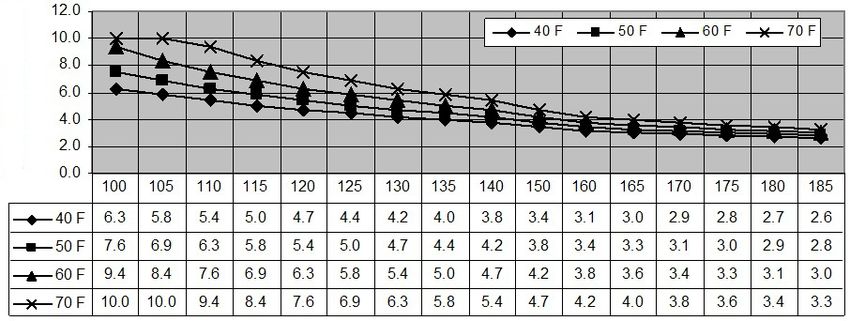
Contents
CONTENTS
Installation Manual
SPECIFICATIONS........................................................................................................................... 4
INTRODUCTION........................................................................................................................... 5
SAFETY GUIDELINES..................................................................................................................... 6
INSTALLATION.............................................................................................................................. 7
General.....................................................................................................................................7
Clearances................................................................................................................................9
Included Accessories...............................................................................................................9
Optional Items........................................................................................................................9
Warning for Installations........................................................................................................11
High-altitude Installations......................................................................................................12
Venting Instructions...............................................................................................................13
Gas supply and gas pipe sizing...............................................................................................20
Water Connections................................................................................................................22
Condensate drain..................................................................................................................23
Electrical Connections............................................................................................................25
Easy-link System.....................................................................................................................26
Multi-unit System...................................................................................................................30
APPLICATIONS............................................................................................................................31
INITIAL OPERATION...................................................................................................................32
Owner's Guide
OPERATING SAFETY................................................................................................................... 34
NORMAL OPERATION................................................................................................................ 36
Temperature controller and Remote controller.....................................................................36
General...................................................................................................................................36
Temperature settings.............................................................................................................37
Temperature table of controller.............................................................................................37
Additional features.................................................................................................................38
Temperature settings on the PCB (Without remote controller)............................................39
Flow.......................................................................................................................................40
Freeze protection system.......................................................................................................40
Maintenance and service.......................................................................................................41
Unit Draining and Filter Cleaning...........................................................................................41
TROUBLESHOOTING...................................................................................................................42
General...................................................................................................................................42
Error Codes...........................................................................................................................44
COMPONENTS DIAGRAM...........................................................................................................47
PARTS LIST.................................................................................................................................51
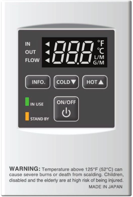
OUTPUT TEMPERATURE CHART................................................................................................54
LIMITED WARRANTY..................................................................................................................55
2 Page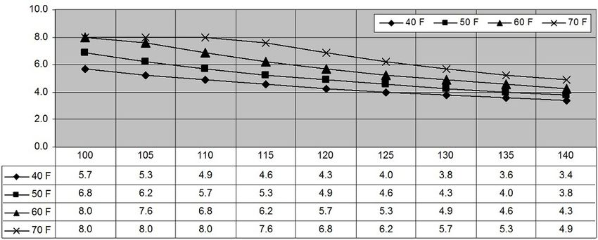
Installation Manual

Installation Manual

                    CONGRATULATIONS
Congratulations and thank you for choosing our tankless water heater.
Before use, we recommend that you read through this safety manual
carefully.  Please refer to the back of the manual for details about the
warranty.  Keep this manual for future reference.
If you lose the manual, contact the manufacturer or your local
distributor. When you call, please tell us the model number and the
serial number of your unit written on the rating plate of the water
heater.

                               3    Page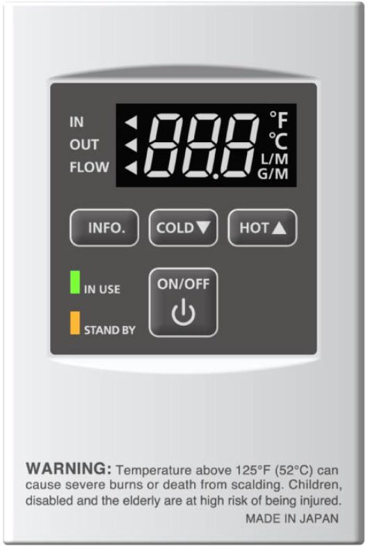
Installation Manual
                                                                                                         Specifications

SPECIFICATIONS
Model                                               T-H3J-DV / 240H           T-H3S-DV / 340H          T-H3-DV / 540H

Natural Gas Input                                   Min.: 15,000               Min.: 15,000            Min.: 15,000
                                        BTU/h
(Operating Range)                                   Max.: 160,000              Max.: 180,000           Max.: 199,000
Propane Input                                       Min.: 13,000               Min.: 13,000            Min.: 13,000
                                        BTU/h
(Operating Range)                                   Max.: 160,000              Max.: 180,000           Max.: 199,000
Gas Connection                                                                    3/4" NPT

Water Connections                                                                 3/4" NPT
                                          MPa
Water Pressure*                                                               0.1 - 1 (15 - 150)
                                          (psi)
Natural gas                                kPa                                Min. 1.24 (5.0)
Inlet Pressure                          (" W.C.)                              Max. 2.61 (10.5)
Propane                                   MPa                                 Min. 1.99 (8.0)
Inlet Pressure                          (" W.C.)                              Max. 3.48 (14.0)
                              Natural      Pa            373                         610                     734
Manifold                       Gas      (" W.C.)        (1.50)                     (2.45)                  (2.95)
Pressure**                                 Pa            523                         672                     821
                             Propane
                                        (" W.C.)        (2.10)                      (2.7)                   (3.3)

Weight                                  kg (lbs.)      26.3 (58)                  26.3 (58)              26.8 (59)

                                          mm                                H 570 x W 450 x D 272
Dimensions
                                          inch                             H 22.4 x W 17.7 x D 10.7

Ignition                                                                      Electric Ignition
                          Supply        VAC / Hz                                  120 / 60
           Consumption

                         Operation       W/A          72.7 / 0.61                 78.2 / 0.65            89.0 / 0.74
Electric

                         Standby         W/A           3.1 / 0.03                 3.1 / 0.03              4.2 / 0.04
        Freeze-
                          W/A             174 / 1.5               174 / 1.5           175 / 1.5
        Protection
*275790 pa (40 psi) or above is recommended for maximum flow.
** The Manifold Pressure is the factory setting and generally should not need adjustment.
NOTE:
• Check the rating plate to ensure this product matches your specifications.
• In accordance with CSA 4.3, CO emission does not exceed 400 ppm for normal input.
• The manufacturer reserves the right to discontinue, or change at any time, specifications or designs
   without notice and without incurring obligation.

                                                             4      Page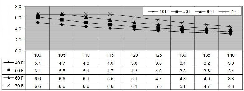
Installation Manual
                                                                                           Introduction

INTRODUCTION
• This manual provides information necessary for the installation, operation, and maintenance
  of the water heater.
• The model description is listed on the rating plate which is attached to the side panel of the
  water heater.
• Please read all installation instructions completely before installing this product.
• If you have any problems or questions regarding this equipment, consult the manufacturer or
  its local representative.
• This equipment is an on-demand, tankless water heater designed to efficiently supply endless
  hot water for your needs.
• These high-efficiency models have a built-in secondary heat exchanger that absorbs latent
  heat from the exhaust gas.
• The T-H3J-DV / 240H, T-H3S-DV / 340H and T-H3-DV / 540H models are only to be installed
  indoors.
• The principle behind tankless water heaters is simple:
                  Intake port                                                  Exhaust

            Exhaust thermistor                                                 Secondary
                                                                               heat exchanger

                                                                               Primary
                    Thermistor                                                 heat exchanger

                                                     Burners
                  Bypass valve

           Water control valve                                                 Gas valves

                Computer board                                                 Fan motor
                                                                               Flow sensor
               Thermistor

                                                                         Condensate
                                                                         drain port
                                        Thermistor
                                                                         Gas
                   Hot water outlet                   Cold water inlet

     *This diagram illustrates tankless water heater design concepts only and does not accurately
       represent the water heater’s physical description.

1.   A hot water tap is turned on.
2.   Water enters the heater.
3.   The water flow sensor detects the water flow.
4.   The computer initiates the fan motor and sends a signal to the igniter to create an ignition spark.
5.   The gas ignites and flames appear within the burner chamber.
6.   Water circulates through the heat exchanger and then gets hot.
7.   Using thermistors to measure temperatures throughout the water heater, the computer modulates
     the gas and water valves to ensure proper output water temperature.
8.   When the tap is turned off, the unit shuts down.

                                                 5    Page
Installation Manual
                                                                                    Safety Guidelines

SAFETY GUIDELINES
                                     SAFETY DEFINITION

                   Indicates an imminently hazardous situation which, if not avoided, will result in
                   death or serious injury.
       DANGER

                   Indicates an imminently hazardous situation which, if not avoided, could result
                   in death or serious injury.
      WARNING

                   Indicates an imminently hazardous situation which, if not avoided, could result
                   in minor or moderate injury.
      CAUTION

                                              GENERAL
   1. Follow all local codes, or in the absence of local codes, follow the most recent edition of CSA B149.1
        Natural Gas, Propane Installation Code.
   2. Properly ground the unit in accordance with all local codes or in the absence of local codes, with CSA
       standard C22.1 Canada Electrical Code Part 1.
   3. Carefully plan where you intend to install the water heater. Please ensure:
             •   Your water heater will have enough combustible air and proper ventilation.
             •   Locate your heater where water leakage will not damage surrounding areas. (please refer to
                  p. 8.)
   4. Check the rating plate for the correct GAS TYPE, GAS PRESSURE, WATER PRESSURE and ELECTRIC
        RATING.
		 *If this unit does not match your requirements, do not install and consult with the manufacturer.
   5. If any problem should occur, turn off all hot water taps and turn off the gas. Then call a trained
        technician or the Gas Company or the manufacturer.

            • Water temperatures over 52 °C (125 °F) can cause severe burns instantly or
              death from scalding. The water temperature is set at 49 °C (120 °F) from the
              factory to minimize any scalding risk. Before bathing or showering always
    WARNING   check the water temperature.
            • Do not store or use gasoline or other flammables, vapors, or liquids in the
              vicinity of this appliance.
            • Do not reverse the water and/or gas connections as this will damage the gas
              valves and can cause severe injury or death.   Follow the diagram on p. 22
              when installing your water heater.
            • Do not use this appliance if any part has been in contact with or been
              immersed in water.   Immediately call a licensed plumber, a licensed gas
              fitter, or a professional service technician to inspect and/or service the unit if
              necessary.
            • Do not disconnect the electrical supply if the ambient temperature will drop
              below freezing.   The Freeze Protection System only works if the unit has
              electrical power.   The warranty will not be covered if the heat exchanger
              is damaged due to freezing.   Refer to the section on the Freeze Protection
              System on p. 40 for more information.

                                                  6   Page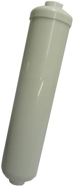
Installation Manual
                                                                                          Installation

INSTALLATION
                                             GENERAL

1. Follow all local codes, or in the absence of local codes, follow the most recent edition of CSA B149.1
   Natural Gas, Propane Installation Code.

2. All gas water heaters require careful and correct installation to ensure safe and efficient operation.
   This manual must be followed exactly.  Read the “Safety Guidelines” section.

3. The manifold gas pressure is preset at the factory. It is computer controlled and should not need
   adjustment.

4. Maintain proper space for servicing. Install the unit so that it can be connected or removed easily.
   Refer to the "Clearances" section on p. 9 for proper clearances.

5. The water heater must be installed in a location where the proper amount of combustible air will be
   available to it at all times without obstructions.

6. The electrical connection requires a means of disconnection, to terminate power to the water heater
   for servicing and safety purposes.

7. Do not install the unit where the exhaust vent is pointing into any opening in a building or where the
   noise may disturb your neighbors. Make sure the vent termination meets the required distance by
   local code from any doorway or opening to prevent exhaust from entering a building. (refer to p. 18.)

8. Particles from flour, aerosols, and other contaminants may clog the air vent, build up and reduce
   the functions of the rotating fan, cause improper burning of the gas, or cause damage to the water
   heater.  Regularly ensure that the area around the unit is dust- or debris-free.  Regular maintenance is
   recommended for these types of environment.

9. T-H3J-DV / 240H, T-H3S-DV / 340H, and T-H3-DV / 540H models are to be installed indoors only.
   These units are equipped with a thermistor and hi-limit switch for the exhaust gas, detecting excess
   temperatures within the flue and enabling the unit to safely stop operations if needed.   These
   components are always monitoring exhaust gas conditions in order to prevent heat damage to PVC,
   CPVC or Polypropylene (Plastic) venting if PVC, CPVC or Polypropylene is used.
   If the exhaust gas temperature exceeds 60 °C (140 °F), these components will enable the unit to safely
   stop operations.

     • These models require a 3" or 4” make-up intake air supply pipe.  The intake pipe must be sealed
       airtight.
     • Air supply pipe can be made of PVC, CPVC or Polypropylene, corrugated stainless steel, or
       Category lll / IV stainless steel.
     • Sidewall venting is recommended for these models.  Vertical venting (roof termination) is
       acceptable.
     • The manufacturer recommends running the exhaust vent and the intake pipe as parallel as
       possible.

                                                 7   Page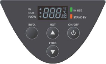
Installation Manual
                                                                                      Installation

        • Installation and service must be performed by a qualified installer (for
          example, a licensed plumber or gas fitter), otherwise the warranty will be
          void.
WARNING • The installer (licensed professional) is responsible for the correct installation
          of the water heater and for compliance with all national, state/provincial,
          and local codes.
        • The manufacturer does not recommend installing the water heater in a pit or
          location where gas and water can accumulate.
        • Do not have the vent terminal pointing toward any operating window, door, or
          opening into a building.
        • Do not install next to any source of airborne debris, such as a clothes dryer,
          that can cause debris to be trapped inside the combustion chamber, unless the
          system is direct-vented.
        • The manufacturer does not recommend installing the water heater in an attic
          due to safety issues.  If you install the water heater in an attic:
          • Make sure the unit will have enough combustion air and proper
             ventilation.
          • Keep the area around the water heater clean.  When dust collects on the
             flame sensor, the water heater will shut down on an error code.
          • Place the unit for easy access for service and maintenance.
                            INCLUDED ACCESSORIES
          • A drain pan, or other means of protection against water damage, is
             required to be installed under the water heater in case of leaks.

             • The warranty will not cover damage caused by water quality.
               • Only potable water or potable water / glycol mixtures can be used with
                  this water heater.  Do not introduce pool or spa water, or any chemically
CAUTION
                  treated water into the water heater.
               • Water hardness levels must not exceed 7 grains per gallon (120 ppm) for
                  single family domestic applications or more than 4 grains per gallon (70
                                  OPTIONAL ITEMS
                  ppm) for all other types of applications.  Water hardness leads to scale
                  formation and may affect / damage the water heater. Hard water scaling
                  must be avoided or controlled by proper water treatment.
               • Water pH levels must be between 6.5 and 8.5
               • Well water must be treated.
             • Do not install the unit where water, debris, or flammable vapors may get into
               the flue terminal.
             • Although the water heater is designed to operate with minimal sound, the
               manufacturer does not recommend installing the unit on a wall adjacent to a
               bedroom, or a room that is intended for quiet study or meditation, etc.
             • Locate your heater close to a drain where water leakage will not do damage
               to surrounding areas.  As with any water heating appliance, the potential for
               leakage at some time in the life of the product does exist. The manufacturer
               will not be responsible for any water damage that may occur.  If you install a
               drain pan under the unit, ensure that it will not restrict the combustion air flow.

                                            8   Page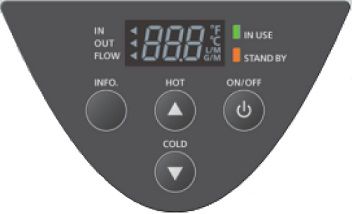
Installation Manual
                                                                                        Installation

                                          CLEARANCES
                                                                                        Top

                   Maintain all clearances around                 Side                        Back
                   the water heater.
                                                                 Front
                                                                                              Side

                                                                             Bottom

           Model             Top          Bottom        Front      Back       Sides
      T-H3J-DV / 240H
                           305 mm         305 mm      102 mm*    13 mm        51 mm
      T-H3S-DV / 340H      (12 in.)       (12 in.)     (4 in.)   (0.5 in.)    (2 in.)
       T-H3-DV / 540H
     *610 mm (24 inches) recommended for maintenance.

                           INCLUDED ACCESSORIES
               Check that these items below are included with the water heater.
                 Installation Manual       Communication Cable
                  and Owner’s Guide        T-H3-DV / 540H only

                                 Qty: 1                 Qty: 1

                                    OPTIONAL ITEMS
#                    Model                     T-H3J-DV / 240H   T-H3S-DV / 340H   T-H3-DV / 540H

1.        Temperature remote controller               ✓                  ✓               ✓
2.             Backflow Preventer                     ✓                  ✓               ✓
3.                 Pipe covers                        ✓                  ✓               ✓
4.               Neutralizer Kit                      ✓                  ✓               ✓
5. 3" ULC S636 PVC Concentric Termination             ✓                  ✓               ✓

                                               9     Page
Installation Manual
Installation
1. Temperature remote controller: 2. Backflow Preventer: TK-BF01
TM-RE40
The temperature remote controller has two
functions. It allows the output temperature from The backflow preventer prevents the backflow
the water heater to be adjusted within the range of air through the exhaust vent. This helps
of 38 °C to 85 °C, and it also works as a diagnostic prevent harmful exhaust gases from entering
tool that will give a concise error code whenever the home, as well as helping to prevent the
there is a problem with the unit. The temperature unit from freezing in areas where cold air can
options are 38 °C (100 °F), 40 °C (105 °F), 43 °C be blown or drawn into the exhaust system.
(110 °F), 45 °C (115 °F), 50 °C (120 °F), 52 °C (125 Install this vent damper in accordance with
°F), 55 °C (130 °F), 57 °C (135 °F), 60 °C (140 °F), 63 the installation instructions and any applicable
codes.
°C (145 °F), 65 °C (150 °F), 68 °C (155 °F), 70 °C (160
°F), 75 °C (165 °F), 80 °C (175 °F) and 85 °C (185 °F).
See the troubleshooting section for information
on possible error codes.
3. Pipe covers: TH-PC03 4. Neutralizer kit: TH-NT01
The neutralizer assembly
neutralizes the condensate
(acidic water) that forms in the
secondary heat exchanger of
The pipe cover protects the plumbing pipes to the water heater.
the water heater from unexpected adjustments. It connects to the condensate
This pipe cover is fixed to the bottom of the water drain port of the water heater
heater, which hides the plumbing and improves by using connectors included
the visual aspects of the whole installation for the with the neutralizer kit. Refer
water heater. to p. 24 for the details.
5. 3" ULC S636 PVC Concentric Termination: TH-CVPVC33
Used when terminating direct-vent (sealed-combustion)
systems, with direct-vent models that require a 76 mm (3
in.) intake and a 76 mm (3 in.) exhaust. This concentric
termination provides the convenience of only having to
make one penetration through a sidewall instead of two
separate penetrations for the intake and exhaust piping.
The termination includes a bird screen, restricting small
animals, pests, and foreign objects from entering into the
vent system.
NOTE: Concentric (single penetration) terminations are
only permitted for sidewall (horizontal) terminations.
Roof (vertical) terminations must use two separate
penetrations.
10 PageInstallation Manual
Installation
WARNING FOR INSTALLATIONS
FOR YOUR SAFETY, READ BEFORE INSTALLATION:
Do not install the heater where water, debris or Do not have the vent terminal pointing toward
flammable vapors may get into the flue terminal. any opening into a building. Do not locate your
This may cause damage to the heater and void the heater in a pit or location where gas and water
warranty. can accumulate.
Prohibited Prohibited
Do not install the water heater vent terminator Do not install next to a dryer or any source
within 914 mm (3 ft.) of any air intake or building of airborne debris that can be trapped inside
opening. (Refer to p. 18.) the combustion chamber, unless the system is
direct vented.
3 ft. (914 mm)
Canada
3 ft. (914 mm) 3 ft. (914 mm)
Canada Canada
11 PageInstallation Manual
Installation
HIGH-ALTITUDE INSTALLATIONS
Check the elevation where your water heater is installed. Set DIPswitches shown in the table below
depending on the altitude.
Altitude
DIPswitches 0 (DEFAULT) Up to 2,500 ft Up to 5,000 ft Up to 7,500 ft Up to 10,100 ft
1 2 3 4 5 6 7 8 9 10 1 2 3 4 5 6 7 8 9 10 1 2 3 4 5 6 7 8 9 10 1 2 3 4 5 6 7 8 9 10 1 2 3 4 5 6 7 8 9 10
ON ON ON ON ON
OFF OFF OFF OFF OFF
T-H3J-DV / 240H and
T-H3S-DV / 340H No. 3 : OFF No. 3 : OFF No. 3 : OFF No. 3 : OFF No. 3 : ON
No. 4 : OFF No. 4 : ON No. 4 : OFF No. 4 : ON No. 4 : ON
No. 5 : OFF No. 5 : OFF No. 5 : ON No. 5 : ON No. 5 : ON
ON 1 2 3 4 5 6 ON 1 2 3 4 5 6 ON 1 2 3 4 5 6 ON 1 2 3 4 5 6 ON 1 2 3 4 5 6
T-H3-DV / 540H OFF OFF OFF OFF OFF
(Lower bank of
No. 2 : OFF No. 2 : OFF No. 2 : OFF No. 2 : OFF No. 2 : ON
DIPswitches)
No. 3 : OFF No. 3 : ON No. 3 : OFF No. 3 : ON No. 3 : ON
No. 4 : OFF No. 4 : OFF No. 4 : ON No. 4 : ON No. 4 : ON
NOTE: The dark squares indicate the direction the DIPswitches should be set to.
T-H3J-DV / 240H and T-H3S-DV / 340H T-H3-DV / 540H
Computer board Computer board
Lower bank of DIPswitches
Bank of DIPswitches
DO NOT adjust any DIPswitches on the upper bank for the T-H3-DV / 540H.
WARNING
12 PageInstallation Manual
Installation
VENTING INSTRUCTIONS
-General-
• Improper venting of this appliance can result in excessive levels of carbon
monoxide which can result in severe personal injury or death.
• Improper installation can cause nausea or asphyxiation, severe injury or death
DANGER from carbon monoxide and flue gases poisoning. Improper installation will void
product warranty.
When installing the vent system, all applicable national and local codes must be
followed. If you install thimbles, fire stops or other protective devices and they
penetrate any combustible or noncombustible construction, be sure to follow all
CAUTION applicable national and local codes.
T-H3J-DV / 240H, T-H3S-DV / 340H, and T-H3-DV / 540H models must be vented in accordance with the
section “Venting of Equipment" of the latest edition of CSA B149.1 Natural Gas and Propane Installation
Code, as well as applicable local building codes.
The use of venting materials approved for Category III/IV appliances is recommended whenever
possible. However, these models may also be vented with plastic pipe materials such as PVC, CPVC,
and Polypropylene. For details, please refer to the Exhaust Vent (Plastic vent) section from p. 14. Vent
installations in Canada which utilize plastic vent systems must use venting that is ULC S636 certified.
General rules for venting water heaters are:
• Place the water heater as close as possible to the vent termination.
• The vent collar of the water heater must be fastened directly to an unobstructed vent pipe.
• Do not weld the vent pipe to the water heater’s vent collar.
• Do not cut the vent collar of the unit.
• The vent must be easily removable from the top of the water heater for normal service and
inspection of the unit.
• The water heater vent must not be connected to any other gas appliance or vent stack.
• Avoid using an oversized vent pipe or using extremely long runs of the pipe.
• For rooftop venting, a rain cap or other form of termination that prevents rain water from
entering into the water heater must be installed.
• Do not common vent or connect any vent from other appliances to the water heater vent.
General rules for vent terminations:
• Avoid locating the water heater vent termination near any air intake devices. These fans can
pick up the exhaust flue products from the water heater and return them to the building. This
can create a health hazard.
• Locate the vent termination so that it cannot be blocked by any debris, at any time. Most codes
require that the termination be at least 305 mm (12 in.) above grade, but the installer may
determine that it should be higher, depending on the job site condition and applicable local
codes.
• A proper sidewall termination is recommended when the water heater is vented through a
sidewall.
• Regarding the clearances from the exhaust termination to the air inlet or opening, refer to p. 18
and p. 19.
13 PageInstallation Manual
Installation
-DIPswitch settings for Vent length-
Set DIPswitches shown in the table below depending on the vent length.
76 mm (3") venting
T-H3J-DV / 240H T-H3-DV / 540H
Vent length
T-H3S-DV / 340H (Upper bank of DIPswitches)
ON 1 2 3 4 5 6 7 8 9 10 ON 1 2 3 4 5 6 7 8
1.5 to 6.1 m
OFF OFF
(5 to 20 ft)
No. 6 : ON No. 3 : ON (DEFAULT)
No. 7 : OFF No. 4 : OFF
ON 1 2 3 4 5 6 7 8 9 10 ON 1 2 3 4 5 6 7 8
OFF OFF 6.4 to 12.2 m
No. 6 : OFF No. 3 : OFF (21 to 40 ft)
No. 7 : OFF No. 4 : OFF
ON 1 2 3 4 5 6 7 8 9 10 ON 1 2 3 4 5 6 7 8
OFF OFF 12.5 to 21.3 m
No. 6 : ON No. 3 : ON (41 to 70 ft)
No. 7 : ON No. 4 : ON
102 mm (4") venting
T-H3J-DV / 240H T-H3-DV / 540H
Vent length
T-H3S-DV / 340H (Upper bank of DIPswitches)
ON 1 2 3 4 5 6 7 8 9 10 ON 1 2 3 4 5 6 7 8
1.5 to 15.2 m
OFF OFF
(5 to 50 ft)
No. 6 : ON No. 3 : ON (DEFAULT)
No. 7 : OFF No. 4 : OFF
ON 1 2 3 4 5 6 7 8 9 10 ON 1 2 3 4 5 6 7 8
OFF OFF 15.5 to 30.5 ft
No. 6 : OFF No. 3 : OFF (51 to 100 ft)
No. 7 : OFF No. 4 : OFF
-Exhaust vent (Plastic vent)-
These models can be vented with a plastic vent which is made of PVC, CPVC, or polypropylene
(temperature rated up to 149 °F). In Canada, plastic venting must be certified to ULC S636 standards.
Item Material Canada
Schedule 40 PVC
Exhaust pipe and
Schedule 40 CPVC
Fittings ULC S636 Certified
Polypropylene
Materials Only
PVC
Pipe Cement/Primer
CPVC
NOTE: Do NOT Use Cellular Foam Core Pipe
14 PageInstallation Manual
Installation
• The maximum length of exhaust vent piping must not exceed 21.3 m (70 ft.) for 76 mm (3”)
venting, which depends on the elevation where the water heater is installed. 30.5 m (100 ft.)
for 102 mm (4”) venting (deducting 1.5 m (5 ft.) for each elbow used in the venting system). Do
not use more than 5 elbows. See the table below.
• When the horizontal vent run exceeds 1.5 m (5 ft.), support the vent run at 0.9 m (3 ft.) intervals
with overhead hangers.
Diameter Max. No. of Elbows Max. Vertical and Horizontal (Total) Vent Length
76 mm (3 in.) 5 21.3 m (70 ft.)
102 mm (4 in.) 5 30.5 m (100 ft.)
*For each elbow added, deduct 1.5 m (5 ft.) from max. vent length.
Max. Vertical or Horizontal (Total) Vent Length
76 mm (3") venting 102 mm (4") venting
No. of Elbows
Elevations up Elevations up Elevations up Elevations up
to 3,000 ft to 6,000 ft to 10,100 ft to 10,100 ft
0 21.3 m (70 ft.) 12.2 m (40 ft.) 7.6 m (25 ft.) 30.5 m (100 ft.)
1 19.8 m (65 ft.) 10.7 m (35 ft.) 6.1 m (20 ft.) 29.0 m (95 ft.)
2 18.3 m (60 ft.) 19.1 m (30 ft.) 4.6 m (15 ft.) 27.4 m (90 ft.)
5 13.7 m (45 ft.) N/A N/A 22.9 m (75 ft.)
Excludes vent terminators, termination elbows, or rain caps
For details on the vent connection to these models, refer to p. 16.
-Plastic Venting Illustrations-
Horizontal Installation Diagram Vertical Installation Diagram
Wall
Roof
Roof
Flashing
Fire stop
Connect between exhaust vent collar and plastic piping.
See the next page for instructions.
For details of the optional items, refer to the Installation manual for each Optional item.
15 PageInstallation Manual
Installation
76 mm (3") vent connection Diagram
1. Connect a 76 mm (3") plastic socket
directly on the exhaust and intake vent 76 mm (3”)
76 mm (3”)
collar of the water heater. plastic straight pipe
plastic straight pipe
2. Connect a 76 mm (3”) plastic straight
pipe to the plastic socket.
76 mm (3”) 76 mm (3”)
plastic socket plastic socket
Exhaust vent collar
Intake vent collar (Female)
(Female)
From 76 mm (3") to 102 mm (4") vent connection Diagram
1. Connect a 76 mm (3") x 102 mm
(4") plastic reducer directly on the
exhaust and intake vent collar of
102 mm (4”) 102 mm (4”)
the water heater. plastic straight pipe plastic straight pipe
2. Connect a 102 mm (4”) plastic
straight pipe to the reducer.
76mm (3") x 102 mm (4") 76mm (3") x 102 mm (4")
plastic reducer plastic reducer
Exhaust vent collar
(Female)
Intake vent collar
(Female)
-Exhaust vent (Stainless steel vent)-
This is a Category IV appliance and must be vented accordingly. The vent system must be sealed airtight.
All seams and joints without gaskets must be sealed with high heat resistant silicone sealant or UL listed
aluminum adhesive tape having a minimum temperature rating of 71 °C (160 °F). For best results, a vent
system should be as short and straight as possible.
• These models are a Category IV appliance and must be vented accordingly with any 4” vent
approved for use with Category III/IV or Special BH type gas vent.
• The manufacturer recommends the “T-Vent” line manufactured by TAKAGI. (Refer to Takagi’s
“T-Vent” brochure for details.) However, the following are also UL listed manufacturers: ProTech
Systems Inc. (FasNSeal), Flex-L Inc., Z-Flex Inc. (Z-Vent III), Metal-Fab Inc., and Heat-Fab Inc. (Saf-T
Vent).
• Follow the vent pipe manufacturer’s instructions when installing the vent pipe.
• Do not common vent this appliance with any other vented appliance. (Do not terminate vent
into a chimney. If the vent must go through the chimney, the vent must run all the way through
the chimney with Category III / IV approved or Special BH vent pipe.)
• The maximum length of exhaust vent piping must not exceed 30.5 m (100 ft.) (deducting 1.5 m
(5 ft.) for each elbow used in the venting system). Do not use more than 5 elbows.
• When the horizontal vent run exceeds 1.5 m (5 ft.), support the vent run at 0.9 m (3 ft.) intervals
with overhead hangers.
16 PageInstallation Manual
Installation
Diameter Max. No. of Elbows Max. Vertical and Horizontal (Total) Vent Length
102 mm (4 in.) 5 30.5 m (100 ft.)
*For each elbow added, deduct 1.5 m (5 ft.) from max. vent length.
No. of Elbows Max. Vertical or Horizontal Vent Length
0 30.5 m (100 ft.)
1 29.0 m (95 ft.)
2 27.4 m (90 ft.)
5 22.9 m (75 ft.)
Excludes vent terminators, termination elbows, or rain caps.
-Stainless steel Vent Illustrations-
Horizontal Installation Diagram Vertical Installation Diagram
Wall Rain Cap
Roof
Roof
Flashing
Fire stop
Sidewall Vent
Terminator
• Regarding the clearances from the exhaust terminal to the air inlet or opening, refer to the
next few pages.
• Follow all vent system manufacturer’s instructions and all local codes.
• Do not common vent or connect any vent from other appliances to these models vent.
• Use 102 mm (4”) Category III/IV approved or Special BH, single or double wall stainless steel
vent pipe.
102 mm (4") vent connection Diagram
Connect a 102 mm (4") stainless
102 mm (4”) 102 mm (4”) stainless
steel vent straight pipe directly on the stainless steel steel vent straight pipe
exhaust and intake vent collar of the vent straight
water heater. pipe
Exhaust vent collar
(Female)
Intake vent collar
(Female)
17 PageInstallation Manual
Installation
-Vent termination clearances-
INSIDE CORNER DETAIL
V Vent terminal
X Air supply inlet
G Area where is not permitted
V
H
A
D
E
V
B B
B V
ED
C ABLE FIXLOSED
OPER C M X
V V I
V
V FIXED
X K
L ED V
CLOS E B
A BL J
OPER
F V B
A
Gas meter / regulator
B
Canada U.S.A
Direct vent and other Direct Other than
than Direct Vent vent Direct Vent
Clearance above grade, veranda, porch, deck, or
A 1 foot 1 foot 1 foot
balcony
4 feet from below or
B Clearance to window or door that may be opened 3 feet 1 foot side opening. 1 foot
from above opening.
C Clearance to permanently closed window * * *
Vertical clearance to ventilated soffit located above
the vent terminator within a horizontal distance
D * * *
of 2 feet (61cm) from the center line of the
terminator
E Clearance to unventilated soffit * * *
F Clearance to outside corner * * *
G Clearance to inside corner * * *
Clearance to each side of center line extended
H 3 feet * *
above meter/regulator assembly
I Clearance to service regulator vent outlet 3 feet * *
Clearance to non-mechanical air supply inlet to 4 feet from below or
J building or the combustion air inlet to any other 3 feet 1 foot side opening. 1 foot
application from above opening.
K Clearance to mechanical air supply inlet 6 feet 3 feet 3 feet
Clearance above paved sidewalk or paved driveway
L 7 feet * 7 feet
located on public property
M Clearance under veranda, porch deck, or balcony 1 foot * *
*For clearances not specified in CSA-B149.1, please use clearances in accordance with local installation codes and
the requirements of the gas supplier.
18 PageInstallation Manual
Installation
-For sidewall terminations-
610 mm For multiple sidewall exhaust terminations (e.g. multi-unit
305 mm (2 ft.) systems), an exhaust termination must be at least 305mm
(1 ft.) (1 ft.) away from another exhaust termination. An exhaust
termination must also be at least 610 mm (2 ft.) away
305 mm from an inside corner. (if the adjacent wall is less than 610
(1 ft.) mm (2 ft.) of length, the minimum required distance away
from the inside corner will be equal to the length of that
Exhaust Inside adjacent wall.)
termination corner
610 mm For multiple-unit, direct-vent sidewall terminations that
305 mm (2 ft.) combine the intake and exhaust into a single penetration,
(1 ft.) space each direct-vent termination at least 305 mm (1 ft.)
away from each other, no matter the orientation. A direct-
vent termination must also be at least 610 mm (2 ft.) away
305 mm from an inside corner. (if the adjacent wall is less than 610
(1 ft.) mm (2 ft.) of length, the minimum required distance away
Combined
intake and from the inside corner will be equal to the length of that
exhaust Inside adjacent wall.)
termination corner
Exhaust
termination For direct-vent sidewall Exhaust and/or
terminations that use two direct-vent sidewall
separate penetrations for terminations should
915 mm
(3 ft.) the intake and exhaust, be at least 610 mm
distance the intake and (2 ft.) away from an 610 mm
exhaust terminations at opposite surface/ (2 ft.)
915 mm
915
mm
(3 ft.) least 915 mm (3 ft.) away wall. Do not place the Exhaust
(3 ft.) from each other, no termination directly termination
matter the orientation. in front of an opening
into a building.
Air supply inlet
A
-For rooftop terminations-
A 610 mm
A (2 ft)
A
A
Air intake
Exhaust termination Exhaust
termination
A: In accordance with local codes Air intake
For multiple-unit rooftop terminations (whether for standard or direct-vent installations) space all
exhaust and intake terminations in accordance with local codes. An exhaust termination must be spaced
from a wall or surface in accordance with local codes as well. In the absence of such a code, an exhaust
termination must be a horizontal distance of at least 610 mm (2 ft.) away from a wall or surface.
Please follow all local and national codes in regards to proper termination
clearances. In the absence of such codes, the above clearances can be used as
CAUTION guidelines. Local codes supersede these guidelines.
19 PageInstallation Manual
Installation
GAS SUPPLY AND GAS PIPE SIZING
-General-
• Check that the type of gas matches the rating plate first.
• Ensure that any and all gas regulators used are operating properly and
providing gas pressures within the specified range shown below. Excess gas
CAUTION inlet pressure may cause serious accidents.
• Conversion of this unit from natural gas to propane or vise versa will void
all warranty. Contact your local distributor to get the correct unit for your
gas type. The manufacturer is not liable for any property and/or personal
damage resulting from gas conversions.
• The minimum and maximum inlet gas pressures are:
Gas type Inlet gas pressure
Natural Gas Min. 1.24 kPa (5.0” W.C.) – Max. 2.61 kPa (10.5” W.C.)
Propane Min. 1.99 kPa (8.0” W.C.) – Max. 3.48 kPa (14.0” W.C.)
• Inlet gas pressure except the ranges in the table above will adversely affect performance. These
pressures are measured when the water heater is in full operation.
• Inlet gas pressure must not exceed the above maximum values; gas pressure above the specified range
will cause dangerous operating conditions and damage to the unit.
• Until testing of the main gas line supply pressure is completed, ensure the gas line to the water heater
is disconnected to avoid any damage to the water heater.
-Gas connections-
1. Install a manual gas shutoff valve between the water heater and the gas supply line.
2. When the gas connections are completed, it is necessary to perform a gas leak test either by applying
soapy water to all gas fittings and observing for bubbles or by using a gas leak detection device.
• The water heater and its individual shutoff valve must be disconnected from the gas supply
piping system during any pressure testing of that system at test pressures in excess of 3.5 kPa
(1/2 psi).
• The water heater must be isolated from the gas supply piping system by closing its individual
manual shutoff valve during any pressure testing of the gas supply piping system at test
pressures equal to or less than 3.5 kPa (1/2 psi).
3. Always purge the gas line of any debris and/or water before connecting to the gas inlet.
NOTICE Size the gas pipe appropriately to supply the necessary volume of gas required for
the water heater using CSA B149.1 or local codes. Otherwise, flow capabilities and
output temperatures will be limited.
20 PageInstallation Manual
Installation
-Natural Gas Supply Piping-
Maximum delivery Capacity of Cubic Feet of Gas per Hour of IPS Pipe carrying Natural Gas with 0.60 Specific Gravity
Based on Pressure Drop of 0.5" W.C.
Based on Energy Content of 1,000 BTU/Cubic ft.: The water heater requires 160 Cubic ft./hr for the T-H3J-DV /
240H, 180 Cubic ft./hr for the T-H3S-DV / 340H, and 199 Cubic ft./hr for the T-H3-DV / 540H.
Unit: Cubic Feet per Hour
Pipe Size Length
Diameter 10' 20' 30' 40' 50' 60' 70' 80' 90' 100' 125' 150' 200'
3/4" 363 249 200 171 152 138 127 118 111 104 93 84 72
1" 684 470 377 323 286 259 239 222 208 197 174 158 135
1 1/4" 1,404 965 775 663 588 532 490 456 428 404 358 324 278
1 1/2" 2,103 1,445 1,161 993 880 798 734 683 641 605 536 486 416
2" 4,050 2,784 2,235 1,913 1,696 1,536 1,413 1,315 1,234 1,165 1,033 936 801
-Propane (LP) Supply Piping-
Maximum Capacity of Propane (LP) Based on 11" W.C. supply pressure at a 0.5" W.C. pressure drop
Unit: kBTU per Hour
Pipe Size Length
Diameter 10' 20' 30' 40' 50' 60' 70' 80' 90' 100' 125' 150' 200'
3/4" 567 393 315 267 237 217 196 185 173 162 146 132 112
1" 1,071 732 590 504 448 409 378 346 322 307 275 252 213
1 1/4" 2,205 1,496 1,212 1,039 913 834 771 724 677 630 567 511 440
1 1/2" 3,307 2,299 1,858 1,559 1,417 1,275 1,181 1,086 1,023 976 866 787 675
2" 6,221 4,331 3,465 2,992 2,646 2,394 2,205 2,047 1,921 1,811 1,606 1,496 1,260
Gas Sizing Example
(Natural Gas) Water
Heater Dryer
199,000 BTU/h 35,000 BTU/h
10' Length
5' Length 3/4" Pipe Size 15' Length 10' Length
1-1/4" Pipe Size A B 1" Pipe Size 1/2" Pipe Size
10' Length
5' Length 1" Pipe Size 10' Length 15' Length
1-1/4" Pipe Size 3/4" Pipe Size C 1/2" Pipe Size
Furnace Range
Gas Meter
120,000 BTU/h 65,000 BTU/h
Based on Energy Content of 1,000 BTU/Cubic ft:
Divide each appliance's BTU requirement by 1,000 BTU/h to get the appliances Cubic Ft. requirement.
Take into account the distance the appliance is from the gas meter, look in the above gas chart to properly size the line.
For sections of the gas line supplying gas to more than one appliance (Ex: Point A to Point B), add up the cubic ft.
requirements of the appliances that are being supplied by that section, and size to the farthest appliance.
For Example: The section from A to B supplies gas to the furnace, range and dryer. Adding up the BTU requirements and
dividing by 1,000 yields a cubic ft. requirement of 220 cubic ft. of gas. The farthest appliance is the range, which is 50 ft.
away from the meter. Looking at the above chart, and under the column of 50 ft., Section A to B needs to be 1" in order to
supply 220 cubic ft.
21 PageInstallation Manual
Installation
-Measuring inlet gas pressure-
1. Turn off all electric power to the water heater if service is to be performed.
2. Turn the manual gas valve located on the outside of the unit clockwise to the
off position.
The water heater cannot perform properly without sufficient inlet gas pressure. Below are instructions on
how to check the inlet gas pressure. THIS IS ONLY TO BE DONE BY A LICENSED PROFESSIONAL.
1. Shut off the manual gas valve on the gas supply line.
2. Remove the screw for the pressure port located on the gas
inlet of the water heater shown in the diagram on the right.
3. Connect the manometer to the pressure port.
4. Re-open the manual gas valve. Check to see that there are
no gas leaks. Open some of the fixtures that use the highest
flow rate to turn on the water heater.
5. Check the inlet gas pressure. When the water heater is on
maximum and minimum burn, the manometer should read
from 1.24 to 2.61 kPa (5.0” to 10.5” W.C.) for Natural gas,
from 1.99 to 3.48 kPa (8.0” to 14.0” W.C.) for Propane.
Pressure port
WATER CONNECTIONS
• Do not use this water heater if any part has been submersed under water.
Immediately call a licensed professional to inspect the water heater to replace
any damaged parts.
• Do not reverse the hot outlet and cold inlet connections to the water heater.
CAUTION
This will not properly activate the water heater.
All pipes, pipe fittings, valves and other components, including soldering materials, must be suitable for
potable water systems.
1. A manual shutoff valve must be installed on the cold water inlet to the water heater between the main
water supply line and the water heater.
2. In addition, a manual shutoff valve is also recommended on the hot water outlet of the unit. If the
water heater is installed within, or subjected to, a closed loop water system, a thermal expansion tank
must be installed.
3. Before installing the water heater, flush
the water line to remove all debris, and
after installation is complete, purge
the air from the line. Failure to do so
may cause damage to the heater.
4. There is a wire mesh filter within
the cold inlet to trap debris from
As Close as
entering your heater. This will need
Possible
to be cleaned periodically to maintain
optimum flow. (Refer to p. 41.) Gas inlet
Hot Cold
outlet inlet Pressure Relief Valve
22 PageInstallation Manual
Installation
-Pressure relief valve-
The water heater has a high-temperature shut off switch built in as a standard safety feature (called a
Hi-Limit switch) therefore a “pressure only” relief valve is required.
• This unit does not come with an approved pressure relief valve.
• An approved pressure relief valve must be installed on the hot water outlet.
• The pressure relief valve must conform to CAN 1-4.4 and installation must follow local codes.
• The discharge capacity must be at least 160,000 BTU/h for the T-H3J-DV / 240H, 180,000 BTU/h for the
T-H3S -DV / 340H, and 199,000 BTU/h for the T-H3-DV / 540H.
• The pressure relief valve needs to be rated for a maximum of 1 MPa (150 psi).
• The discharge piping for the pressure relief valve must be directed so that the hot water cannot splash
on anyone or on nearby equipment.
• Attach the discharge tube to the pressure relief valve and run the end of the tube to within 152
mm (6 in.) from the floor. This discharge tube must allow free and complete drainage without any
restrictions.
• If the pressure relief valve installed on the water heater discharges periodically, this may be due to a
defective thermal expansion tank or defective pressure relief valve.
• The pressure relief valve must be manually operated periodically to check for correct operation.
• No valve must be placed between the relief valve and the water heater.
CONDENSATE DRAIN
• The water heater does not include a built-in condensate neutralizer cartridge for reducing the pH level
of condensate water. If local codes dictate that condensate must be neutralized prior to drainage, a
condensate neutralizer must be installed. An accessory Neutralizer assembly is sold separately.
• In the absence of applicable local codes and regulations, the manufacturer recommends that
condensate be disposed of into a standard drain. Connect a drain tube from the condensate drain port
(shown below) located on the bottom of the water heater to a standard drain.
Follow all code requirements Condensate drain port
of the local authority on
condensate neutralizers and
whether or not they are required
for the installation.
23 PageInstallation Manual
Installation
-Condensate Drain Connections-
Discharge condensate (acidic water) in accordance with all local codes
and common safety practices.
WARNING
The water heater is a high efficiency condensing water heater that produces condensate (acidic water).
The acidic condensate generated in the secondary heat exchanger can be neutralized by the Neutralizer
accessory.
Case A: If a neutralizer is not required
1. Connect a 1/2” FPT X 3/8” (or 1/2”) HB Adaptor to the condensate drain port at the bottom of the
water heater.
2. Connect a condensate drain tube to the 1/2” FPT X 3/8” (or 1/2”) HB Adaptor. The manufacturer
recommends the material of the condensate tube be either EPDM or PVC.
3. Leave an adequate amount of space between the end of the drain tube and the actual drain, to
facilitate proper drainage.
Case B: If a neutralizer is required (installing the Neutralizer assembly)
1. Connect a 1/2” FPT X 3/8” MPT Adaptor to the condensate drain port at the bottom of the water
heater.
2. Connect a Neutralizer to the 3/8” MPT connection of the adaptors. There is a flow direction indicator
on the neutralizer. Please orient the neutralizer in the proper direction.
3. Connect a 1/2” drain tube to the other end of neutralizer.
4. Leave an adequate amount of space between the end of the drain tube and the actual drain, to
facilitate proper drainage.
Case A Case B
Condensate Condensate
drain port drain port
1/2" FRT x 3/8" MPT
1/2" FRT x 3/8" (Included with
(or 1/2") HB Neutralizer accessory)
Neutralizer cartridge
(Included with
3/8" or 1/2" Neutralizer accessory)
Condensate
drain tube 3/8" MPT x 1/2" HB
(Included with
Neutralizer accessory)
1/2" Condensate
Drain drain tube
Drain
Adequate space Adequate space
24 PageInstallation Manual
Installation
• The condensate drain is at atmospheric pressure (non-pressurized) and
therefore must be allowed to drain freely with gravity only. Please ensure that
there are no blockages along the condensate drain tube. All portions of the
WARNING
condensate drain (neutralizer and drain tube) must be at a lower elevation
than the water heater to prevent condensate water from building up inside
the heat exchanger.
• Condensate cannot be effectively neutralized if the neutralizer elements inside
the Neutralizer accessory have been completely consumed. If this happens,
condensate will remain acidic and can possibly cause damage to items such as
pipes, concrete, etc., if drained improperly.
• The Neutralizer cartridge is designed to last for 3 years before replacement.
However, the actual life of the neutralizer may vary, depending on the
application and usage. Please ensure that the cartridge is properly replaced
before the neutralizer elements have been completely consumed.
• All preventative measures and safety practices must be adhered to when
draining condensate. The manufacturer will not be responsible for any damage
caused by condensate.
• A drain pan, or other means of protection against water damage, is required to
be installed under the water heater in case of leaks.
ELECTRICAL CONNECTIONS
Follow the electrical code requirements of the local authority having jurisdiction.
In the absence of such requirements, follow the latest edition of CSA C22.1
Canadian Electrical Code, Part 1.
WARNING
When servicing or replacing parts within the water heater, label all wires prior to
disconnection to facilitate an easy and error-free reconnection. Wiring errors can
cause improper and dangerous operation. Verify proper operation after servicing.
CAUTION
1. The water heater requires 120 VAC, 60 Hz electrical power supply that is properly grounded.
2. The use of a surge protector is recommended in order to protect the unit from power surges.
25 PageInstallation Manual
Installation
EASY-LINK SYSTEM
(Available on the T-H3-DV / 540H Indoor only)
-General-
The T-H3-DV / 540H water heaters can be connected with allowable heaters (see the table below)
with communication cables to work as a multiple-unit manifold system.
• The Easy-Link system allows up to 4 units to manifold together.
• A communication cable (gray color) comes with each T-H3-DV / 540H model.
You can manifold from 2 to 4 units without the need for a multi-unit controller. A 4-unit system
has full automatic modulation between 13,000 BTU/h (Propane) or 15,000 BTU/h (Natural gas)
to 796,000 BTU/h.
Easy-Link connection with allowable heaters
T-H2-DV / 520H
T-H3-DV / 540H
Gas In
Hot Out
Cold In
• The Easy-Link system is limited up to 4 units. If you connect more than 4 units,
only the first 4 units will work as a part of the Easy-Link system. The other
additional units will not work.
• Only listed models on the table above can be combined together as an Easy-
CAUTION Link System. Different models cannot be combined together to form an
Easy-Link System.
When the T-H3-DV / 540H is connected to previous models as part of an Easy-
link system, Contact the manufacturer.
WARNING
-Easy-Link Connection Procedures-
1. Verify the set temperatures of all units within the system. Every single water heater must be set to the
same set temperature.
26 PageInstallation Manual
Installation
2. Select one unit to be the “PARENT” unit.
3. “PARENT” unit :
Locate the two banks of DIPswitches at the bottom left of the computer board of the unit that you
select to be the “PARENT” unit. Change DIPswitch No. 1 on the lower bank of DIPswitches to the
ON position. See the computer board diagram below. Do not change any DIPswitches on any of the
“CHILD” units.
4. Between the “PARENT” and the “CHILD-1” units :
Connect the “PARENT” connector of the “PARENT” unit to the “1” connector of the “CHILD-1” unit.
5. Between the “CHILD-1” and the “CHILD-2” units :
Connect the “2” connector of the “CHILD-1” unit to the “1” connector of the “CHILD-2” unit.
6. Between the “CHILD-2” and the “CHILD-3” units :
Connect the “2” connector of the “CHILD-2” unit to the “1” connector of the “CHILD-3” unit.
7. Make sure the remote controller and/or temperature controller display the unit #. The numbering
system automatically allocates the unit # to each water heater in the Easy-Link system, in accordance
with the table below.
Type of unit Unit # of easy-link
Parent 1
Child 2, 3 or 4
(A) T-H3-DV / 540H Computer board
To change the DIPswitch Easy-Link /
Multi-unit
settings for the Easy-Link
connectors
system, locate the bank of are next to
DIPswitches at the bottom the computer
left of the computer board. board.
Do not adjust the upper
bank of DIPswitches.
Upper bank of DIPswitches
Lower bank of DIPswitches
(B) Basic diagram of connections between the Easy-Link System units.
Temperature controller
or
PARENT unit Remote controller CHILD-1 unit CHILD-2 unit CHILD-3 unit
Connectors Connectors Connectors Connectors
2 1
2 1
2 1
2 1
PARENT
PARENT
PARENT
PARENT
OFF
OFF
OFF
OFF
ON
ON
ON
ON
1 2 3 456
1 2 3 456
1 2 3 456
1 2 3 456
Lower bank of Lower bank of Lower bank of Lower bank of
DIPswitches DIPswitches DIPswitches DIPswitches
Communica on cable
NOTE: The dark squares indicate the direction the DIPswitches should be set to.
27 PageInstallation Manual
Installation
NOTICE Either a temperature controller or a remote controller is required for the Easy-
Link system for ease of usage and maintenance.
(C) Examples of incorrect settings and /or connections
CASE 1: Wrong DIPswitch setting on the "PARENT" unit
• Unless you change DIPswitch No. 1
of the “PARENT” unit to the “ON” PARENT unit CHILD-1 unit
position, the system will not work
as an Easy-Link system. The units
2 1
2 1
will operate as individual units.
PARENT
PARENT
OFF
OFF
ON
ON
Wrong Setting
1 2 3 4 5 6
1 2 3 4 5 6
Lower bank of Lower bank of
DIPswitches DIPswitches
Communicaon cable
CASE 2: Wrong connections between the "PARENT" unit and the
"CHILD-1" unit
• If you connect the "1" (or "2") connector of the “PARENT” unit to the “PARENT" (or "1")
connector of the “CHILD-1” unit, the system will not work as an Easy-link system. The units will
operate as individual units.
PARENT unit CHILD-1 unit
Connectors Connectors
2 1
2 1
PARENT unit CHILD-1 unit
Connectors Connectors
PARENT
PARENT
2 1
2 1
OFF
OFF
ON
ON
OR
1 2 3 4 5 6
1 2 3 4 5 6
PARENT
PARENT
Lower bank of Lower bank of
DIPswitches DIPswitches
OFF
OFF
ON
ON
1 2 3 4 5 6
1 2 3 4 5 6
Communicaon cable Lower bank of Lower bank of
DIPswitches DIPswitches
Wrong
Connections Communicaon cable
Wrong
Connections
28 PageInstallation Manual
Installation
CASE 3: Wrong connections between the "CHILD-1" unit and the "CHILD-2" unit
• If you connect the “PARENT” connector of the “CHILD-1” unit to the “1” connector of the
“CHILD-2” unit, the “CHILD-2” unit will operate as an individual unit, and will not be part of the
Easy-Link system.
PARENT unit CHILD-1 unit CHILD-2 unit
Connectors Connectors Connectors
2 1
2 1
2 1
PARENT
PARENT
PARENT
OFF
OFF
OFF
ON
ON
ON
1 2 3 4 5 6
1 2 3 4 5 6
1 2 3 4 5 6
Lower bank of Lower bank of Lower bank of
DIPswitches DIPswitches DIPswitches
Communicaon cable
Wrong
Connections
Connecting two “PARENT” connectors together from two separate units may
damage the computer board. The communication cable has a female end and
a male end so it’s impossible to have a PARENT-to-PARENT connection with the
WARNING communication cable. Do not splice or modify connectors.
CASE 4: Remote controller connected to incorrect unit
• Either a temperature controller or a remote controller has to be connected to the “PARENT”
unit. If the remote controller is connected to a “CHILD” unit, it will only control that particular
individual “CHILD” unit and will not control the Easy-Link system as a whole.
• The temperature controller of the “CHILD” unit will not control the unit on the system.
PARENT unit CHILD-1 unit
Connectors Connectors
Remote controller
2 1
2 1
PARENT
PARENT
OFF
OFF
ON
ON
1 23 456
1 23 456
Lower bank of Lower bank of
DIPswitches DIPswitches
Wrong Connections
Communicaon cable
29 PageYou can also read