DIR Series Indoor/Outdoor Infrared Heaters - Glen Dimplex ...
←
→
Page content transcription
If your browser does not render page correctly, please read the page content below
DIR Series Indoor/Outdoor
Infrared Heaters
                                                          Model
                                                          DIR15A10GR
                                                          DIR18A10GR
                                                          DIR22A10GR
                                                          DIR30A10GR

                                                     Power/On

IMPORTANT SAFETY INFORMATION: Always read this manual first
                                               Low     Med      High

                                                       1hr   2hr
                                                         Timer

before attempting to install or use this heater. For your safety, always
                                                on           Standby

comply with all warnings and safety instructions contained in this manual
to prevent personal injury or property damage.

To view the full line of Dimplex products, please visit
www.dimplex.com

                                                                       7215590000R04
Table of Contents
Welcome & Congratulations. . . . . . . . . . . . . . . . . . . 3
IMPORTANT INSTRUCTIONS. . . . . . . . . . . . . . . . . 4
Heater Installation . . . . . . . . . . . . . . . . . . . . . . . . . . 6
Site Selection. . . . . . . . . . . . . . . . . . . . . . . . . . . . . 9
Installation. . . . . . . . . . . . . . . . . . . . . . . . . . . . . . 11
Electrical Installation . . . . . . . . . . . . . . . . . . . . . . 13
Operating Instructions . . . . . . . . . . . . . . . . . . . . . . 16
Maintenance Instructions. . . . . . . . . . . . . . . . . . . . 19
Troubleshooting. . . . . . . . . . . . . . . . . . . . . . . . . . . 20
Warranty. . . . . . . . . . . . . . . . . . . . . . . . . . . . . . . . . 21
Technical Support. . . . . . . . . . . . . . . . . . . . . . . . . . 23
This manual covers installation ! NOTE: Procedures and
and maintenance. Read carefully techniques that are
before attempting to install, considered important enough
operate, or service the Infrared to emphasize.
heater. CAUTION: Procedures and
techniques which, if not
carefully followed, will result in
damage to the equipment.
WARNING: Procedures
and techniques which, if not
carefully followed, will expose
the user to the risk of fire,
serious injury, or death.
2 www.dimplex.comWelcome & Congratulations
Thank you and congratulations for choosing to purchase a Dimplex
DIR Heater.
Please carefully read and save these instructions.
CAUTION: Read all instructions and warnings carefully before
starting installation. Failure to follow these instructions may result
in a possible electric shock, fire hazard and will void the warranty.
Please record your model and serial numbers for future reference.
Model and serial numbers can be found on the Model and Serial
Number Label of your heater.
Power/On
Low Med High
1hr 2hr
Timer
on Standby
Power/On
Low Med High
1hr 2hr
Timer
on Standby
NO NEED TO RETURN TO THE STORE
Questions with operation or assembly? Require Parts Information?
Product Under Manufacturer’s Warranty?
Contact us at: www.dimplex.com/customer_support
For Troubleshooting and Technical Support
OR Toll-Free 1-888-346-7539
Please have your model number and
product serial number ready. (See above)
3IMPORTANT INSTRUCTIONS
When using electrical appliances, ⑥D
o not operate any heater
basic precautions should always with a damaged cord or after it
be followed to reduce the risk of malfunctions, has been dropped
fire, electric shock, and injury to or damaged in any manner.
persons, including the following: Return heater to authorized
① Read all instructions before service facility for examination or
installing or using this heater. mechanical adjustment or repair.
②U
se this heater only as ⑦T
o disconnect heater, turn off
described in this manual. Any power to heater circuit at main
other use not recommended by disconnect switch, and turn off
the manufacturer may cause power to heater circuit at main
fire, electric shock, or injury to disconnect panel.
persons. ⑧D
o not insert or allow foreign
③T
his heater is hot when in use. objects to enter any ventilation
To avoid burns, do not let bare or exhaust opening as this may
skin touch hot surfaces. Keep cause an electric shock or fire, or
combustible materials, such damage the heater.
as furniture, pillows, bedding, ⑨T
o prevent a possible fire, do not
papers, clothes, and curtains block air intakes or exhaust in
at least 0.9 m (3.0 ft) from the any manner.
front of the heater and keep
⑩A
heater has hot and arcing or
them away from sides and rear
sparking parts inside. Do not use
restrictions.
it in areas where gasoline, paint,
④E
xtreme caution is necessary or flammable liquids are used or
when any heater is used by or stored.
near children or invalids and
⑪D
o not touch the heater during
whenever the heater is left
operation as the body becomes
operating and unattended.
hot and could causes burns.
⑤D
o not operate any heater after Particular attention has to
it malfunctions. Disconnect be given where children and
power at service panel and have vulnerable people are present.
heater inspected by a reputable
⑫T
his appliance is not intended
electrician before reusing.
for use by persons (including
children) with reduced physical,
4 www.dimplex.comIMPORTANT INSTRUCTIONS
sensory or mental capabilities, WARNING: The heater must not
or lack of experience and be used if the glass panels are
knowledge, unless they have damaged.
been given supervision or
instruction concerning use ! NOTE: Changes or
of the appliance by a person modifications not expressly
responsible for their safety. approved by the party
responsible for compliance
⑬D
o not allow any cables, could void user's authority to
furnishing, flammable materials, operate the equipment.
or other items come in contact
with any surface of the heater.
⑭ The heater must not be located
immediately below a socket-
outlet. The heater must not be
located in front of a socket-
outlet. They should be located
outside the physical footprint of
the units to minimize heat build-
up behind the heater.
⑮ SAVE THESE INSTRUCTIONS.
CAUTION
RISK OF ELECTRIC SHOCK
DO NOT OPEN
NO USER-SERVICEABLE PARTS INSIDE
SAVE THESE INSTRUCTIONS
FOR FUTURE REFERENCE
5Heater Installation
HOW TO OPERATE THE HEATER:
What's included with your Dimplex DIR Series Heater
• IR Heater
• Operating and Installation Instructions
• One small box containing 2 sets of brackets and mounting hardware
• One remote controller
Figure 1
Brackets for wall or ceiling mounting
Terminal box
Remote control
Power/On
Schott Nextrema®: Low Med
1hr 2hr
High
glass panel
Timer
on Standby
Technical Specification
Power/On
MODEL NAME DIR15A10GR DIR18A10GR DIR22A10GR DIR30A10GR
Low Med High
1hr 2hr
Timer
on Standby
Voltage 120V 60Hz 240V 60Hz 240V 60Hz 240V 60Hz
Rated power
(Watts) 1500 1800 2200 3000
Installation Wall-mounted Wall-mounted
Wall-mounted Wall-mounted
Mounting height Ceiling-mounted Ceiling-mounted
Minimum 2.4 M (8 ft.) 2.4 M (8 ft.) 2.4 M (8 ft.) 2.4 M (8 ft.)
Electric protection
I I I I
class
Outdoor Rated Yes Yes Yes Yes
Unit dimensions
902 x 170 x 128 902 x 170 x 128 902 x 170 x 128 1286 x 170 x 128
LxWxH (mm / in)
35-1/2 x 6-3/4 x 5 35-1/2 x 6-3/4 x 5 35-1/2 x 6-3/4 x 5 50-5/8 x 6-3/4 x 5
(without bracket)
6 www.dimplex.comHeater Installation
2. Within USA, electrical installation
RISK OF FIRE/ shall be made in accordance with
EXPLOSION the National Electrical Code.
This heater should not be 3. Within Canada, electrical
used in potentially explosive installation shall be made
atmospheres. Do not use in according to the provisions of
areas where gasoline, paint section 62 of the Canadian
or flammable liquids are used electrical code part 1.
or stored. 4. Wiring procedures and
Installation minimum connections shall be in
clearances specified on the accordance with the national and
heater nameplate and in the local codes having jurisdiction.
owner's manual must be
followed. CAUTION: Disconnect electric
power supply before working on
circuit wiring to prevent electric
Before installation, read this shock.
manual carefully and keep for
future reference. CAUTION: When installing
outdoors we recommend the
The heater must be installed in heater is positioned where it will be
accordance with the manufacturer’s protected from exposure to extreme
installation instructions. weather such as snow and ice.
1. This equipment shall be installed
only by qualified personnel who CAUTION: This heater must be
are familiar with the construction grounded.
and operation of the apparatus CAUTION: Electrical connection
and hazard involved. must have ground fault protection
WARNING: The heater is (GFCI or GFI).
fitted with an electrical connection
box and should be connected as CAUTION: A circuit breaker is
a fixed installation by a licensed required for proper installation, do
electrical professional. Wiring not load beyond 80% capacity.
procedures and connections should CAUTION: High temperature,
be in accordance with the National risk of fire, keep electrical cords,
Electric Code (NEC) and local drapery, furnishings, and other
codes.
7Heater Installation
combustibles at least 0.9 m (3 ft) or controls must not be within
from the front of the heater and reach of a person in the
away from the side and rear. bathtub, shower or swimming
5. The heater is designed for pool.
outdoor and indoor use and 11. Ensure that the heater had been
should not be used for any securely fastened in its final
other purpose. Any other use mounting position.
not recommended by the 12. The heater can be only installed
manufacturer may cause fire, horizontally.
electric shock, or injury to
persons. 13. D
O NOT install the heater
vertically. Failure to do this
6. Before commencing installation may cause the heating element
make sure the electrical supply within the tube to sag and
voltage is the same as that cause premature burnout.
shown on the rating plate of the
heater. 14. There are no user-serviceable
parts inside the heater. Any
7. The heater must be mounted at servicing other than regular
least 2.4 m (8 ft) above ground cleaning of the heater should
level. For other clearance please be performed by an authorized
refer to the diagram included in service professional.
these instructions.
8. To reduce the risk of fire, do not
store or use gasoline or other WARNING: The heater must
flammable vapors and liquids in not be used if the glass panels
the vicinity of the heater are damaged.
9. The heater is not intended for
use in bathrooms, laundry areas ! NOTE: This heater comes
or similar indoor areas. Never with a pair of stainless steel
locate heater where it may fall adjustable angle mounting
into a bathtub, pool, spa, or other brackets. The adjustable
water container. angle enables the heater to
be installed on horizontal and
10. Do not install the heater directly inclined surfaces.
near a bathtub, shower or
swimming pool. Any switches
8 www.dimplex.comSite Selection
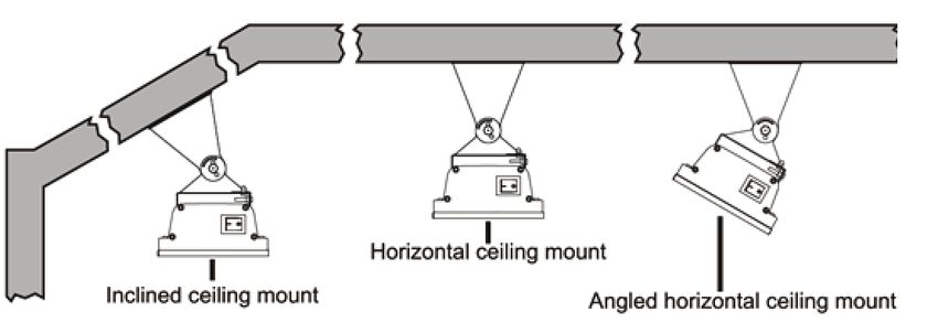
SITE SELECTION:
Ceiling mounted (DIR15A10GR, DIR18A10GR).
ARNING: DIR22A10GR and DIR30A10GR CANNOT
W
be ceiling-mounted.
Horizontal ceiling-mount
Inclined ceiling-mount Angled horizontal ceiling-mount
Correct Installation Incorrect Installation
CEILING CEILING CEILING
WALL
WALL
WALL
WARNING: The heater must Clearances
never be installed in the upwards To ensure that all minimum
or inwards facing position, the clearances are achieved please refer
heating surface must always be to the diagrams on page 10.
positioned to direct the heat in a
downwards or outwards direction.
WARNING: DO NOT install the
heater vertically. Failure to follow
these instructions can cause the
heating element within the tube
to sag and cause premature
burnout.
9Site Selection
Minimum clearances when mounting the heater parallel with a ceiling.
CEILING
165mm
Fans, lights and
(6.5") sprinkler fittings
WALL
Min. MUST NOT
be below heater
600mm 600mm
(23.6") (23.6")
Min. Min. CEILING
910mm (35.4") Min. to surfaces (ie. table tops, etc.)
WALL
2400mm (96") Min. from floor
3000mm (118.1") Max. from floor (recommended)
600mm (23.6") Min.
IR heater, same minimum
clearance requirements
for both ends of heater
installation
Minimum clearances when mounting the heater at an angle to the ceiling.
CEILING
150mm Fans, lights and
(5.9")
Min. sprinkler fittings
MUST NOT
WALL
be below heater
600mm
(23.6")
Min. 1500mm
(59.1")
Min. CEILING
910mm (35.4") Min. to surfaces (ie. table tops, etc.)
WALL
2400mm (96") Min. from floor
3000mm (118.1") Max. from floor (recommended)
600mm (23.6") Min.
IR heater, same minimum
clearance requirements
for both ends of heater
installation
Minimum clearances when mounting the heater on A VERTICAL WALL.
CEILING Wall-mounted
Fans, lights and
sprinkler fittings
installation
240mm (9.4")
(DIR15A10GR,
WALL
Min. MUST NOT
be below heater
DIR18A10GR,
1500mm (59.1") DIR22A10GR,
Min.
CEILING DIR30A10GR)
105mm
910mm (35.4") Min. to surfaces (ie. table Correct Installation
(4.1") Min.
tops, etc.) 2400mm (96") Min. from floor
WALL
CEILING
600mm (23.6") Min.
WALL
IR heater, same minimum
clearance requirements
for both ends of heater
installation
10 www.dimplex.comInstallation
WARNING: Mounting of the infrared heater and its connection to the
electric mains should be carried out only by qualified professionals according
to the Electrical Installation Regulations and Power System Safety Standards
and comply with all national and local electrical codes.
1. O
pen the package and carefully remove the heater.
2. R
emove the packing paper sheet from the end of heater.
3. Take out one pair of mounting brackets. These adjustable brackets allow
direct ceiling or wall mount, and come with preset angle options of parallel,
30°, 45° and height 165 mm (6.5 in).
117mm (4.6")
100mm (3.9")
15mm
20mm
(0.8")
(0.6")
7mm (0.3")
165mm
(6.5")
4. Use the above diagrams as a
guideline for proper installation.
Select the heater location on
the ceiling or wall by locating
the stud or structural beams to
ensure secure fastening of the
heater. Ensure that all minimum
clearances are achieved. Model “B”
Number MINIMUM DISTANCE
5. Install two brackets on the
ceiling or wall with the following DIR15A10GR 500 mm ±50 mm (19.7" ± 2.0")
minimum recommended bracket DIR18A10GR 500 mm ±50 mm (19.7" ± 2.0")
distance “B”. Ensure brackets are DIR22A10GR 500 mm ±50 mm (19.7" ± 2.0")
level and not slanted diagonally. DIR30A10GR 650 mm ±50 mm (25.6" ± 2.0")
11Installation
6. Set the adjustable angle mounting brackets to the desired angle and
fasten brackets with an adjustable wrench.
F
or ceiling-mounted installation, the available mounting angles are
restricted to 0° and 30° only.
F
or wall-mounted installation, the available mounting angles are restricted
to 30° and 45° only.
For the DIR 2200W / 3000W, ceiling mounted installation is prohibited.
CEILING
WALL
7. Hang the heater on the brackets and firmly tighten bolts on the bracket to
compress the two plates together as shown in Figure A.
! NOTE: Depending on material
and design of wall or ceiling structural
elements, the heater must be secured
with the correct fasteners. The
weight of the heaters DIR15A10GR,
DIR18A10GR, DIR22A10GR is
up to 5.3 KG (11.7 lbs.). The weight
of the heater DIR30A10GR is
6.8 KG (15.0 lbs.). The
installationstructure and
hardwaremust be able to
hold 5 times the weight of
the heater.
12 www.dimplex.comElectrical Installation
WARNING: This Heater MUST 3. The heater must not be located
be permanently installed and hard immediately below an electrical
wired by an authorized / licensed connection. Power point should
electrical professional. Do not not be located at the back of the
perform maintenance or carry out heater. The power point needs to
installation or assembly procedure be located outside the physical
while electrical power is switched on. footprint of the heater to minimize
heat build-up behind the heater.
CAUTION: A circuit breaker is 4. If the heater is to be mounted on
required for proper installation. Do an incline (e.g. Vaulted ceiling),
not load beyond 80% capacity. The ensure the electrical connection
type of circuit breaker must be C point is below the heater.
curve type.
1. DIR15A10GR (1500W) is
designed for connection to the
120V~ 60Hz electric mains
equipped with a grounding wire.
2. DIR18A10GR (1800W),
DIR22A10GR (2200W) and
DIR30A10GR (3000W) heaters
are designed for connection to
the 240V~ 60Hz electric mains
equipped with a grounding wire.
13Wiring Instructions
WIRING INSTRUCTIONS:
DIR15A10GR is to be wired to a 120V circuit while DIR18A10GR,
DIR22A10GR and DIR30A10GR are to be wired to a 240V circuit. These
heaters must be wired to the this circuit in such a way that the heater can
be turned off directly at the circuit 240
breaker in the event of an emergency.
V 15A
Sample wiring diagrams
L2 have been included below for quick
L2 reference.
240 V
Heater Power
L1 Supply
Junction L1 240 V 15A
Box L2 L2 Breaker
G G Panel
240 V
Heater Power
L1 Supply
Junction L1 Use GFCI breaker
Box for outdoor installations
Breaker
G Indoor Double Pole G Panel
240 V Switch
L2 L2
L2 L2
Wall 240 breaker
Use GFCI V
Heater L1 Power
for outdoor installations
IndoorSwitch
Double Pole L1 Supply
Junction L1 L1
240 V Switch
Box L2 L2 Breaker
G L2 L2 G
Wall Panel
240 V
Heater L1 Use switch rated for outdoor Power
Switch L1 Supply
Junction applications,
L1
if applicable
L1
Box Breaker
G G
Panel
Use switch rated for outdoor
applications, if applicable
120 V 15A
N (White) N
120 V
Heater L (Black) Power
L Supply
Junction 120 V 15A
Box N (White) N Breaker
G G
Panel
120 V
Heater L (Black) Power
L Supply
Junction Use GFCI breaker
Box for outdoor installations
Breaker
G G
Indoor Single Pole Panel
N (White) 120 V Switch N
120 breaker
Use GFCI V
Power
for outdoor installations
Heater L (Black) L Supply
Junction Wall
L1 Single Pole
L1
Indoor
Box N (White)
Switch
120 V Switch N Breaker
G G Panel
120 V
Use switch rated for outdoor Power
Heater L (Black) L Supply
Junction L1
Wall
applications, if applicable
L1 Use GFCI breaker
Box Switch for outdoor installations
Breaker
G G Panel
14 Use switch rated for outdoor www.dimplex.com
applications, if applicable Use GFCI breaker
for outdoor installationsElectrical Installation
1. Check product label for correct 4. Remove the screws holding the
voltage and wattage. Make sure junction box cover. Make the
power source conforms to the electrical connections using wire
heaters requirements. nuts (not supplied).
2. The junction box on the top of For 120 V units: The green wire
the heater has a gasket side connects to the ground wire from
access cover. The junction box the power source. The black wire
inlet is drilled and threaded for a connects to the live wire from the
standard 19 mm (1/2") weather power source. The white wire
tight conduit fittings. The installing connects to the neutral wire from
electrician will need to provide the the power source.
appropriate rigid metallic, flexible For 240 V units: The green wire
or liquid tight conduit, conduit connects to the ground wire from
fittings for installation location. the power source. The black wire
3. For outdoor installation all connects to L1 (live) from the
connections must be made power source. The white wire
in accordance with local connects to L2 (live) from the
electrical code regulations for power source.
outdoor wiring. Only use wiring 5. Assemble the junction box cover
components approved for outdoor & gasket. Ensure that the junction
use with minimum NEMA Type 4x box cover gasket (supplied with
or equivalent. unit) is installed to maintain
rain water ingress protection
rating of the heater. Failure to
install correctly will void the
manufacturer’s warranty.
15Operating Instructions
WARNING: The heater must be properly installed before it is used.
Slight crackles may be heard during the heating or cooling period. This is a
normal part of the operation of the heater.
RISK OF FIRE/EXPLOSION
• This heater should not be used in potentially explosive atmospheres or
environments. Do not use in areas where gasoline, paint or flammable
liquids are used or stored.
• Keep electrical cords, drapery, furnishings, insulation and other
combustibles at least 0.9 m (3 ft) from the front of the heater and away
from the top, rear, and sides of the unit.
• To prevent possible fires, do not block or allow foreign objects to enter
air intakes.
ELECTRICAL SHOCK HAZARD
• Do not operate heating unit after a malfunction. Disconnect power at the
service panel and have the heater inspected by a qualified electrician
before reusing.
• Use this heater only as described in this manual. Any other use is not
recommended by the manufacturer and may result in fire, electric shock,
or injury.
• Do not insert or allow foreign objects to enter any ventilation or exhaust
opening as this may cause an electric shock or fire, or damage the heater.
RISK OF INJURY/BURN
• The heating unit and discharge area will be hot when in use. To avoid
burns, do not let bare skin touch the heating unit or glass surface on
heating unit.
• Do not attempt to service or clean heater while unit is operating, as there
is a hazard from electric shock and burn potential from hot surfaces. To
avoid the risk of burn or injury wait a minimum of 6 hours for the heater to
cool before attempting to clean or service.
! NOTE: After switching on the heater for the first time following extended
periods on non-use, the appliance may produce a slight odor for a short time.
This is normal and will not affect the use of the heater.
16 www.dimplex.comOperating Instructions
! NOTE: To prevent unpleasant burnt odor, it is recommended to keep the
heater clean preventing accumulation of dust build up
! NOTE: It is recommended that the distance between the heater and the
remote be less than 3 m (9.8 ft.), and the remote control must be pointed
directly to the receiver on the front panel during the operation.
Green LED indicators
(timer)
Green LED indicators
(timer)
Red LED indicators Remote
Red LED indicators
(temperature
setting) control
(temperature setting)
1. S
witch on the circuit breaker, 2. P
oint the remote control directly
the heater will begin in Standby to the receiver, press ‘LOW’,
mode. At this time the lowest heat ‘MED’, ‘HIGH’ to set your desired
temperature setting LED will be temperature setting.
flashing to indicate the unit is in
Standby.
Low power level Medium power level High power level
CAUTION: There is a built in 3. T
o set the heater to standby
safety feature that will automatically mode point the remote control
trigger the heater to go into standby directly at the receiver and press
mode after eight hours of continuous ‘Standby’. At this time the lowest
operation. At this time the lowest heat temperature setting LED will
heat temperature setting LED will be be flashing to indicate the unit is
flashing to indicate the safety feature in Standby mode.
has executed.
17Operating Instructions
TIMER FUNCTION
Your Dimplex infrared heater comes with a programmable timer that will
automatically place the heater in Standby mode after 1, 2 or 3 hours of
operation. To operate the timer point the remote control directly to the
receiver and press ’1 hr’, a single green LED light will illuminate directly
beside the heating LED’s, this will trigger the heater to automatically go into
Standby mode after 1 hour of operation. Once in Standby mode a single red
LED will be flashing.
1 hour timer
1 hour timer
1. To set the timer for 2 hours of 2. To set the timer for 3 hours of
operation point the remote control operation point the remote control
directly to the receiver and press directly to the receiver and press
‘2 hr’, a single green LED light ‘1 hr’ and ‘2 hr’, both green LED
will illuminate with a gap between lights will illuminate, this will trigger
the heat and timer LED’s on the the heater to automatically go into
unit, this will trigger the heater Standby mode after 3 hours of
to automatically go into Standby operation.
mode after 2 hours of operation.
22 hour
hour timer
timer 33hour
hour timer
timer
18 www.dimplex.comMaintenance Instructions
ELECTRIC SHOCK HAZARD
• Potentially lethal voltages are present. Be sure to turn off the unit at the
circuit breaker before attempting any maintenance
RISK OF INJURY/BURN
• Do not attempt to service or clean heater while unit is operating, as there
is a hazard from electric shock, and injury potential from hot heating
elements.
• Maintenance and repair must be performed by qualified personnel only.
WARNING: When replacing the WARNING: All maintenance
ruby bulb or when cleaning the should only be carried out by a
unit ensure that if hard wired the qualified electrician or installation
circuit is disconnected from the professional.
main power supply.
2. It is necessary to periodically
! NOTE: ALWAYS ENSURE (once a year) check the electric
THAT THE BULB HAS COOLED cable contacts and terminal
BEFORE HANDLING. connectors for good tightening.
1. Do not handle the halogen 3. Before cleaning the unit, the
bulb with bare hands. If it is power shall be turned off at the
inadvertently touched, remove circuit breaker panel, and the
finger marks with a soft cloth heating unit must be cool to the
and methylated spirit or rubbing touch to prevent bodily injury.
alcohol. Otherwise, the marks will
4. If the body becomes dirty, wipe off
burn into the quartz emitter during
dust with a towel. The radiating
use causing premature heater
boards should be wiped in cold
failure.
condition with a damp soft rag.
It is recommended to clean the
unit every 3 months for peak
performance.
WARNING: Never immerse the
heater in water! Doing so could
cause damage, bodily injury or
death.
19Troubleshooting
Troubleshooting prior to calling a service technician:
SYMPTOM RECOMMENDED ACTION
Will not heat / No operation Check that power is connected and switched
indicator LED on
This is caused by oil or dust left over from the
Heater smells when first used manufacturing process and will stop after a
short time
Faint smell for short periods after This is normal and should stop after a short
turning on the heater time
This is the result of build-up debris and dust in
Heater smells when turned on
the heater, Switch the heater off and allow it to
after periods of non-use
cool down and then clean before operating
Clinking noises when heater This is expansion and contraction noises of
is turned on and after being the heaters metal components and is a normal
turned off function of the heater
Exposure to extreme ambient conditions such
as high winds / excessively cold temperatures
can lower the heating performance of an
Poor heating performance outdoor installation
Unit is not installed in correct position,
possibly too high or heater is too small for
recommended area.
When to contact the authorized service technician or your dealer:
SYMPTOM RECOMMENDED ACTION
There is a burning smell and or Turn off the heater, and contact your
strange sounds (other than normal dealer
expansion and contraction noises)
coming from the unit
When associated circuit breaker Turn off the heater, and contact your
(safety, ground) trips or a fuse is blown dealer or a certified electrical technician
Poor heating performance Incorrectly sized installation, contact your
dealer for more information
Poor heating performance Faulty heater element, turn off the heater,
and contact your dealer
Will not heat / No operation indicator Check that power is connected and
switched on, if still faulty turn off the
heater, and contact your dealer or a
certified electrical technician.
20 www.dimplex.comWarranty
One Year Limited Warranty (Glen Dimplex Americas herein) warrants
such products to be free from defects in
Products to which this limited warranty material and workmanship for a period of 12
applies months from the date of the first purchase
of such product.
This limited warranty applies to your newly
The limited 12 month warranty period
purchased Dimplex Infrared Indoor/Outdoor
also applies to any implied warranties that
Heater. This limited warranty applies only to
may exist under applicable law. Some
purchases made in any province of Canada
jurisdictions do not allow limitations on how
except for Yukon Territory, Nunavut, or
long an implied warranty lasts, so the above
Northwest Territories or in any of the 50
limitation may not apply to the purchaser.
States of the USA (and the District of
Columbia) except for Hawaii and Alaska.
This limited warranty applies to the original
purchaser of the product only and is not What this limited warranty does not cover
transferable.
This limited warranty does not apply
to products that have been repaired
Products excluded from this limited (except by Glen Dimplex Americas or its
warranty authorized service representatives) or
otherwise altered. This limited warranty
IR Ruby Heating Elements are not covered does further not apply to defects resulting
by this limited warranty and are the sole from misuse, abuse, accident, neglect,
responsibility of the owner/purchaser. incorrect installation, improper maintenance
Products purchased in Yukon Territory, or handling, or operation with an incorrect
Nunavut, Northwest Territories, Hawaii, power source.
or Alaska are not covered by this limited
warranty. Products purchased in these
States, provinces, or territories are sold AS What you must do to get service under this
IS without warranty or condition of any kind limited warranty
(including, without limitation, any implied
Defects must be brought to the
warranties or conditions of merchantability
attention of Technical Service by
or fitness for a particular purpose) and
contacting 1-888-346-7539. Please have
the entire risk of as to the quality and
proof of purchase, catalogue/model and
performance of the products is with the
serial numbers available when calling.
purchaser, and in the event of a defect the
Limited warranty service requires a proof
purchaser assumes the entire cost of all
of purchase of the product.
necessary servicing or repair.
What Glen Dimplex Americas will do in the
What this limited warranty covers and for
event of a defect
how long
In the event a product or part covered by this
Products covered by this limited warranty
limited warranty is proven to be defective
have been tested and inspected prior to
in material or workmanship during the 12
shipment and, subject to the provisions of
month limited warranty period you have the
this warranty, Glen Dimplex Americas Ltd.
following rights:
21Warranty
• Glen Dimplex Americas will in its sole jurisdiction. The provisions of the United
discretion either repair or replace such Nations Convention on Contracts for the
defective product or part without charge. Sale of Goods shall not apply to this limited
If Glen Dimplex Americas is unable warranty or the sale of products covered by
to repair or replace such product or this limited warranty.
part, or if repair or replacement is not
commercially practicable or cannot be
timely made, Glen Dimplex Americas What Glen Dimplex Americas and its dealers
may, in lieu of repair or replacement, and service agents are also not responsible
choose to refund the purchase price for for:
such product or part. IN NO EVENT WILL GLEN DIMPLEX
• Limited warranty service will be AMERICAS, OR ITS DIRECTORS,
performed solely by dealers or service OFFICERS, OR AGENTS, BE LIABLE
agents of Glen Dimplex Americas TO THE PURCHASER OR ANY THIRD
authorized to provide limited warranty PARTY, WHETHER IN CONTRACT, IN
services. TORT, OR ON ANY OTHER BASIS, FOR
ANY INDIRECT, SPECIAL, PUNITIVE,
• The purchaser is responsible for EXEMPLARY, CONSEQUENTIAL, OR
removal and transportation of such INCIDENTAL LOSS, COST, OR DAMAGE
product or part (and any repaired or ARISING OUT OF OR IN CONNECTION
replacement product or part) to and WITH THE SALE, MAINTENANCE, USE,
from the authorized dealer’s or service OR INABILITY TO USE THE PRODUCT,
agent’s place of business.
EVEN IF GLEN DIMPLEX AMERICAS
• This limited warranty does not entitle OR ITS DIRECTORS, OFFICERS, OR
the purchaser to on-site or in-home AGENTS HAVE BEEN ADVISED OF
services. On-site or in-home services THE POSSIBILITY OF SUCH LOSSES,
may be performed at the purchaser’s COSTS OR DAMAGES, OR IF SUCH
specific request and expense at Glen LOSSES, COSTS, OR DAMAGES ARE
Dimplex Americas then-current rates for FORESEEABLE. IN NO EVENT WILL
such services. GLEN DIMPLEX AMERICAS, OR ITS
• Glen Dimplex Americas will not be OFFICERS, DIRECTORS, OR AGENTS
responsible for, and the limited warranty BE LIABLE FOR ANY DIRECT LOSSES,
services shall not include, any expense COSTS, OR DAMAGES THAT EXCEED
incurred for installation or removal of THE PURCHASE PRICE OF THE
the product or part (or any replacement PRODUCT.
product or part) or any labour or SOME JURISDICTIONS DO NOT ALLOW
transportation costs. Such costs shall be THE EXCLUSION OR LIMITATION OF
the purchaser’s responsibility. INCIDENTAL OR CONSEQUENTIAL
DAMAGES, SO THE ABOVE LIMITATION
How State and Provincial law apply OR EXCLUSION MAY NOT APPLY TO
THE PURCHASER.
This limited warranty gives you specific
legal rights, and you may also have other
rights which vary from jurisdiction to
22 www.dimplex.comTechnical Support
Technical and troubleshooting support, as well as
a list of replacement parts can be found on
www.dimplex.com/customer_support
1-888-346-7539 | www.dimplex.com
In keeping with our policy of continuous product
improvement, we reserve the right to make
changes without notice.
© 2019 Glen Dimplex AmericasChaufferette infrarouge intérieure /
extérieure de la série DIR
Modèles
DIR15A10GR
DIR18A10GR
DIR22A10GR
DIR30A10GR
CONSIGNES DE SÉCURITÉ IMPORTANTES : Lire le présent manuel
Power/On
Low Med High
1hr 2hr
Timer
avant d’essayer d’installer ou d’utiliser cet appareil. Pour votre sécurité,
on Standby
toujours respecter tous les avertissements et suivre les consignes de
sécurité données dans le présent manuel afin de prévenir les blessures
ou les dommages matériels.
Pour découvrir la gamme complète des produits Dimplex, visitez le site
www.dimplex.com
7215590000R04Table des matières
Bienvenue . . . . . . . . . . . . . . . . . . . . . . . . . . . . . . . . 3
INSTRUCTIONS IMPORTANTES . . . . . . . . . . . . 4
Installation de l’appareil de chauffage. . . . . . . . . . . 6
Choix de l’emplacement . . . . . . . . . . . . . . . . . . . 10
Installation. . . . . . . . . . . . . . . . . . . . . . . . . . . . . . 11
Installation électrique. . . . . . . . . . . . . . . . . . . . . . 15
Utilisation. . . . . . . . . . . . . . . . . . . . . . . . . . . . . . . . 16
Maintenance . . . . . . . . . . . . . . . . . . . . . . . . . . . . . 19
Dépannage . . . . . . . . . . . . . . . . . . . . . . . . . . . . . . 20
Garantie. . . . . . . . . . . . . . . . . . . . . . . . . . . . . . . . . 21
Service d'assistance technique . . . . . . . . . . . . . . . 23
Le présent manuel traite de ! NOTE : Marches à suivre et
l’installation et de l’entretien de techniques d’importance suffi
l’appareil. Lire attentivement le santes pour être soulignées.
manuel avant de tenter d’installer, MISE EN GARDE : Le non-
d’utiliser ou d’entretenir l’appareil respect de ces procédures
de chauffage infrarouge. et techniques provoquera
l’endommagement de
l’équipement.
AVERTISSEMENT : Marches
à suivre et techniques
qui,si elles ne sont pas bien
respectées, exposeront
l’utilisateur à des risques
d’incendie, de blessure grave
ou de décès.
2 www.dimplex.comBienvenue
Merci et félicitations d’avoir acheté un appareil de chauffage infrarouge
Dimplex.
Lire ces instructions attentivement et les conserver.
MISE EN GARDE : Lire attentivement toutes les instructions et
tous les avertissements avant de commencer l’installation. Le
non-respect de ces instructions pourrait entraîner un risque de
décharge électrique ou d’incendie et annuler la garantie.
Prendre en note les numéros de modèle et de série de l’appareil à des
fins de consultation ultérieure. Ceux-ci se trouvent sur l’étiquette du
numéro de modèle et du numéro de série de l’appareil.
Power/On
Low Med High
1hr 2hr
Timer
on Standby
Power/On
Low Med High
1hr 2hr
Timer
IL N’EST PAS NÉCESSAIRE D’ ALLER AU MAGASIN
on Standby
Des questions à propos de l'utilisation ou du montage?
Besoin d'information sur les pièces ?
Besoin d’information à propos d’un produit sous garantie du fabricant ?
Communiquer avec nous à : www.dimplex.com/customer_support
Pour le dépannage et le Service d'assistance technique
OU Sans frais au 1 888 346-7539
Afin que nous puissions mieux vous servir, veuillez avoir votre
modèle et votre numéro de série à portée de main ou veuillez inscrire
votre produit en ligne avant de téléphoner (voir ci-dessus).
3INSTRUCTIONS IMPORTANTES
Lorsqu’un appareil électrique est lorsqu’il est en marche et laissé
utilisé, il est important de toujours sans surveillance.
prendre des précautions de base ⑤ Ne pas utiliser un appareil de
pour réduire les risques d’incendie, chauffage après que celui-ci ait
de décharges électriques et de présenté une défaillance. Couper
blessures. Il faut notamment le courant au panneau électrique
appliquer ce qui suit : et faire inspecter l’appareil par
① Lire toutes les instructions avant un électricien qualifié avant de
d’installer ou d’utiliser cet appareil l’utiliser à nouveau.
de chauffage. ⑥ Ne pas se servir d’un appareil
② Se servir de l’appareil uniquement de chauffage si le cordon est
de la façon décrite dans le endommagé, si l’appareil a
présent manuel. Toute autre présenté une défaillance, ou s’il
utilisation non recommandée est tombé ou est endommagé de
par le fabricant pourrait causer quelque façon que ce soit. Pour
un incendie, des décharges faire vérifier ou réparer l’appareil,
électriques ou des blessures. ou pour faire effectuer une mise
③ L’appareil de chauffage devient au point mécanique, retourner
chaud lorsqu’il est en marche. l’appareil dans un centre de
Pour éviter les brûlures, ne service autorisé.
pas laisser la peau nue entrer ⑦ Pour débrancher l’appareil,
en contact avec les surfaces couper l’alimentation électrique
chaudes. Garder tout matériel du circuit de l’appareil à
combustible, comme des l’interrupteur général principal,
meubles, des oreillers, de la de même qu’au tableau de
literie, du papier, des vêtements commande principal.
et des rideaux, à au moins 0,9 ⑧ Ne pas introduire ou laisser
mètre (3,0 pieds) du devant de entrer de corps étrangers dans
l’appareil. De plus, garder tout la prise d’air de ventilation ou
matériel combustible à l’écart des la bouche de sortie d’air, car
côtés et de l’arrière de l’appareil, cela peut occasionner des
en respectant les restrictions à décharges électriques, provoquer
cet égard. un incendie ou endommager
④ Faire preuve d’une grande l’appareil de chauffage.
prudence lorsque l’appareil est ⑨ Pour éviter un incendie, ne pas
utilisé par des enfants ou des obstruer les entrées ou la sortie
personnes handicapées, ou à d’air d’aucune façon.
proximité de ces derniers, et
⑩ Tout appareil de chauffage
4 www.dimplex.comINSTRUCTIONS IMPORTANTES
contient des pièces qui chauffent ⑬N
e laisser aucun câble, meuble,
et qui produisent un arc électrique matériau inflammable ou autre
ou des étincelles. Ne pas objet entrer en contact avec toute
utiliser dans des endroits où surface de l’appareil.
de l’essence, de la peinture ou
⑭L
’appareil ne doit pas être installé
d’autres liquides inflammables
juste au-dessous d’une prise de
sont utilisés ou entreposés.
courant. Il ne doit pas non plus
⑪ Ne pas toucher l’appareil pendant être installé devant une prise
son fonctionnement, car il devient de courant. L’appareil devrait
chaud et pourrait causer des être installé à l’extérieur de
brûlures. En présence d’enfants l’espace physique occupé par les
et de personnes vulnérables, une prises pour réduire au minimum
attention particulière doit leur être l’accumulation de chaleur derrière
portée. l’appareil.
⑫ Cet appareil n’est pas conçu ⑮ CONSERVER CES INSTRUCTIONS
pour être utilisé par des
AVERTISSEMENT : L’appareil
personnes (y compris des
de chauffage ne doit pas être
enfants) aux capacités physiques,
utilisé si les panneaux en verre
sensorielles ou mentales
sont endommagés.
réduites, ou par des personnes
manquant d’expérience ou de ! NOTE : Les changements ou
connaissances, à moins qu’elles les modifications n’ayant pas
ne soient supervisées lorsqu’elles fait l’objet d’une approbation
utilisent l’appareil ou qu’elles expresse de la partie
aient reçu des instructions responsable de la conformité
d’utilisation par une personne auront pour effet d’annuler le
responsable de leur sécurité. droit d’utilisation de l’appareil par
l’utilisateur.
MISE EN GARDE
RISQUE DE CHOC ÉLECTRIQUE
NE PAS OUVRIR
AUCUN ENTRETIEN À FAIRE SUR
LES PIÈCES INTÉRIEURES
CONSERVER CE MANUEL À DES FINS
DE CONSULTATION ULTÉRIEURE
5Installation de l’appareil de chauffage
UTILISATION DE L’APPAREIL DE CHAUFFAGE :
Contenu de la boîte de l’appareil de chauffage Dimplex
• Appareil de chauffage infrarouge
• Instructions d’installation et d’utilisation
• Petite boîte contenant 2 ensembles de supports et la quincaillerie
de fixation
• Télécommande
Figure 1
Supports pour installations murales
ou au plafond
Boîtier de
connexions
Télécommande
Power/On
Panneau en verre Low Med
1hr 2hr
High
NextremaMD de Schott
Timer
on Standby
Technical Specification
Power/On
NOM DU MODÈLE DIR15A10GR DIR18A10GR DIR22A10GR DIR30A10GR
Low Med High
1hr 2hr
Timer
on Standby
Tension 120V 60 Hz 240V 60 Hz 240V 60 Hz 240V 60 Hz
Puissance nominale
1500 1800 2200 3000
(en watts)
Installation murale Installation murale
Installation Installation au plafond Installation au plafond Installation murale Installation murale
au plafond au plafond
Hauteur de
fixation minimale 2,4 M (8 pi) 2,4 M (8 pi) 2,4 M (8 pi) 2,4 M (8 pi)
Classe de protection
I I I I
électrique
Conçu pour l’extérieur Oui Oui Oui Oui
Dimensions de
l’appareil 902 x 170 x 128 902 x 170 x 128 902 x 170 x 128 1286 x 170 x 128
L x l x H (mm/po) 35-1/2 x 6-3/4 x 5 35-1/2 x 6-3/4 x 5 35-1/2 x 6-3/4 x 5 50-5/8 x 6-3/4 x 5
(sans support)
6 www.dimplex.comInstallation de l’appareil de chauffage
dispositions de la section 62 de la
RISQUE D’INCENDIE/ première partie du Code canadien de
D’EXPLOSION l’électricité.
Cet appareil ne doit pas être utilisé 4. Les procédures de câblage et les
dans un endroit à atmosphère connexions doivent être conformes
potentiellement explosive. Ne pas au code national ainsi qu’aux codes
faire fonctionner l’appareil dans locaux applicables.
des endroits où de l’essence,
de la peinture ou des liquides MISE EN GARDE : Couper
inflammables sont utilisés ou la source d’alimentation électrique
entreposés. avant de manipuler le câblage du
Les dégagements minimaux circuit pour prévenir les décharges
indiqués sur la plaque signalétique électriques.
et dans le manuel de l’appareil MISE EN GARDE : Lors de
doivent être respectés au moment l’installation à l’extérieur, nous
de l’installation. recommandons que l’appareil soit
Avant l’installation, lire placé à un endroit où il sera protégé
attentivement le présent manuel des conditions météorologiques
et le conserver à des fins de extrêmes et des intempéries, comme
consultation ultérieure. la neige et la glace.
L’appareil de chauffage doit MISE EN GARDE : Cet appareil
être installé conformément aux doit être mis à la terre.
instructions d’installation du fabricant. MISE EN GARDE : Le
1. L’appareil de chauffage est raccordement électrique doit avoir
équipé d’un boîtier de connexions une protection contre les fuites à la
électriques et doit être raccordé terre (disjoncteur différentiel de fuite
en tant qu’installation fixe par un à la terre).
professionnel de l’électricité agréé. MISE EN GARDE : Un
Les procédures de câblage et les disjoncteur est nécessaire pour que
connexions doivent être conformes l’installation soit adéquate; ne pas
au code national de l’électricité ainsi le charger à plus de 80 % de sa
qu’aux codes locaux. capacité.
2. Aux États-Unis, l’installation MISE EN GARDE : Une
électrique doit être effectuée température élevée engendre
conformément au National Electrical des risques d’incendie; garder les
Code. cordons électriques, les rideaux,
3. Au Canada, l’installation électrique l’ameublement et les autres matières
doit être faite conformément aux combustibles à au moins 0,9 mètre
7Installation de l’appareil de chauffage
(3 pieds) du devant de l’appareil, de 10. Ne pas installer l’appareil
même qu’à l’écart des côtés et de directement à proximité d’une
l’arrière de l’appareil. baignoire, d’une douche ou d’une
piscine. Les interrupteurs et les
5. L’appareil de chauffage est conçu commandes ne doivent pas être à la
pour une utilisation extérieure ou portée d’une personne qui se trouve
intérieure et ne doit pas être utilisé à dans la baignoire, la douche ou la
d’autres fins. Toute autre utilisation piscine.
non recommandée par le fabricant
pourrait causer un incendie, des 11. S’assurer que l’appareil a bien
décharges électriques ou des été fixé dans sa position de fixation
blessures. finale.
6. Avant de commencer 12. L’appareil ne peut être installé
l’installation, s’assurer que la qu’en position horizontale.
tension d’alimentation électrique
est identique à celle indiquée sur la 13. NE PAS installer l’appareil en
plaque signalétique de l’appareil. position verticale, car l’élément
chauffant situé dans le tube
7. L’appareil doit être installé pourrait se relâcher et s’épuiser
à au moins 2,4 mètres (8 pieds) prématurément.
au-dessus du sol. Pour les autres
dégagements, se reporter au 14. Il n’y a aucune pièce dont
schéma inclus dans les présentes l’entretien peut être effectué par
instructions. l’utilisateur à l’intérieur de l’appareil.
Tout entretien autre que le nettoyage
8. Afin de réduire les risques régulier doit être exécuté par
d’incendie, ne pas conserver ou un professionnel en entretien et
utiliser de l’essence ou d’autres gaz réparation autorisé.
et liquides inflammables à proximité
de l’appareil de chauffage. AVERTISSEMENT : L’appareil
de chauffage ne doit pas être
9. L’appareil n’est pas conçu pour utilisé si les panneaux en verre
être utilisé dans une salle de bain, sont endommagés.
une salle de lavage ou dans d’autres
pièces intérieures semblables. Ne ! NOTE : Deux supports de
jamais installer l’appareil à un endroit fixation à angle réglable en acier
où il est susceptible de tomber dans inoxydable sont inclus. L’angle
une baignoire, dans une piscine, réglable permet l’installation
dans un spa ou dans tout autre de l’appareil sur des surfaces
réservoir d’eau. horizontales et inclinées.
8 www.dimplex.comChoix de l’emplacement
CHOIX DE L’EMPLACEMENT :
Installé au plafond (DIR15A10GR, DIR18A10GR).
AVERTISSEMENT : Les modèles DIR22A10GR et DIR30A10GR
NE PEUVENT PAS être installé au plafond.
Installation horizontale
au plafond
Installation inclinée
Installation horizontale en
au plafond
angle au plafond
Installation correcte Installation incorrecte
PLAFOND PLAFOND PLAFOND
MUR
MUR
MUR
AVERTISSEMENT : L’appareil AVERTISSEMENT : NE PAS
ne doit jamais être installé face installer l’appareil en position
vers le haut ou vers l’intérieur; la verticale. Si cette instruction
surface chauffante doit toujours n’est pas respectée, l’élément
être positionnée pour diriger chauffant situé dans le tube
la chaleur vers le bas ou vers pourrait se relâcher et s’épuiser
l’extérieur. prématurément.
Dégagements
Pour s’assurer que tous les
dégagements minimaux sont
respectés, se reporter aux schémas
à la page 10.
9Choix de l’emplacement
Dégagements minimaux lors de la fixation de radiateur parallèlement au plafond.
PLAFOND
Les ventilateurs, les
6,5 po dispositifs d’éclairage et
(165 mm) les raccords des gicleurs
min.
MUR
NE DOIVENT PAS se
trouver sous l’appareil.
23,6 po 23,6 po
(600 mm) (600 mm)
min. min. PLAFOND
Distance min. de 35,4 po (910 mm) par rapport aux
surfaces (c.-à-d. dessus de table, etc.)
MUR
Distance min. de 96 po (2400 mm) par rapport au sol
Distance max. de 118,1 po (3000 mm) par rapport au 23,6 po (600 mm) min.
sol (recommandé)
Appareil de chauffage infrarouge : mêmes
exigences de dégagement minimum pour les
deux extrémités l’appareil installé
Dégagements minimaux lors de la fixation de l’appareil en angle au plafond.
PLAFOND
5,9 po Les ventilateurs, les
(150 mm) dispositifs d’éclairage et
min. les raccords des gicleurs
NE DOIVENT PAS se
MUR
trouver sous l’appareil.
23,6 po
(600 mm)
min. 59,1 po
(1500 mm) PLAFOND
min.
Distance min. de 35,4 po (910 mm) par rapport aux
surfaces (c.-à-d. dessus de table, etc.)
MUR
Distance min. de 96 po (2400 mm) par rapport au sol
Distance max. de 118,1 po (3000 mm) par rapport au 23,6 po (600 mm) min.
sol (recommandé)
Appareil de chauffage infrarouge : mêmes
exigences de dégagement minimum pour les
deux extrémités l’appareil installé
Dégagements minimaux lors de la fixation de l’appareil SUR UN MUR VERTICAL.
PLAFOND Installation au mur
9,4 po Les ventilateurs, les
dispositifs d’éclairage et
(DIR15A10GR,
(240 mm)
min. les raccords des gicleurs DIR18A10GR,
MUR
NE DOIVENT PAS se
trouver sous l’appareil. DIR22A10GR,
59,1 po
(1500 mm) DIR30A10GR)
min.
PLAFOND
Distance min. de 35,4 po (910 mm) Installation correcte
4,1 po par rapport aux surfaces (c.-à-d. dessus
de table, etc.) PLAFOND
(105 mm)
MUR
min. Distance min. de 96 po (2400 mm) par 23,6 po (600 mm) min.
rapport au sol –
MUR
Appareil de chauffage infrarouge : mêmes
exigences de dégagement minimum pour les
deux extrémités l’appareil installé
10 www.dimplex.comInstallation
AVERTISSEMENT : L’installation de l’appareil de chauffage infrarouge
et son raccordement au réseau électrique doivent être effectués uniquement
par des professionnels qualifiés conformément aux réglementations sur les
installations électriques et aux normes de sécurité des systèmes électriques et
doivent être conformes à tous les codes électriques nationaux et locaux.
1. O
uvrir l’emballage et retirer soigneusement l’appareil.
2. Retirer la feuille de papier d’emballage au bout de l’appareil.
3. Sortir une paire de supports de fixation. Ces supports réglables permettent la
fixation directe au plafond ou au mur, et offrent des options d’angle prédéfinies
117mm (4,6 po)
100mm (3,9 po)
(0,8 po)
(0,6 po)
20mm
15mm
7mm (0,3 po)
165mm
(6,5 po)
des parallèles, soit 30°, 45°, ainsi
qu’une hauteur de 165 mm (6,5 po).
4. Utiliser les schémas ci-dessus
comme guide pour effectuer une
installation adéquate. Choisir
l’emplacement de l’appareil au
plafond ou au mur en repérant les
montants ou les poutres de charpente
qui permettront une fixation sûre
N° de «B»
de l’appareil. S’assurer que tous
modele DISTANCE MINIMUM
les dégagements minimums sont
respectés. DIR15A10GR 500 mm ±50 mm (19,7 po ± 2,0 po)
DIR18A10GR 500 mm ±50 mm (19,7 po ± 2,0 po)
5. Installer deux supports au plafond
DIR22A10GR 500 mm ±50 mm (19,7 po ± 2,0 po)
ou au mur avec la distance minimale
suivante recommandée entre les DIR30A10GR 650 mm ±50 mm (25,6 po ± 2,0 po)
11Installation
supports (« B »). S’assurer que les supports sont de niveau et ne sont pas
inclinés en diagonale.
6. Régler les supports de fixation à l’angle souhaité et les fixer à l’aide d’une clé
à molette.
Pour une installation au plafond, les angles de fixation possibles sont de 0° et
30° uniquement.
Pour une installation murale, les angles de fixation possibles sont de 30°
et 45° uniquement.
Pour le DIR 2200W et DIR 3000W, l'installation au plafond est interdite.
PLAFOND
MUR
7. Accrocher l’appareil sur les supports et serrer fermement les boulons des
supports pour comprimer les deux plaques, comme illustré sur la figure A.
! NOTE : Selon le matériau et la conception des éléments de structure du
plafond ou du mur, l’appareil doit être installé au moyen de pièces de fixation
appropriées. Le poids des appareils
DIR15A10GR, DIR18A10GR,
DIR22A10GR peut atteindre
11,7 lb (5,3 kg). Le poids de
l’appareil DIR30A10GR est de
6,8 kg (15 lb). L’emplacement
choisi pour l’installation doit
pouvoir supporter 5 fois le
poids de l’appareil.
12 www.dimplex.comInstallation électrique
AVERTISSEMENT : Cet 3. L’appareil ne doit pas être
appareil DOIT être installé et installé immédiatement sous un
directement raccordé au réseau raccordement électrique. La prise
électrique de façon permanente de courant ne doit pas être située
par un professionnel de l’électricité à l’arrière de l’appareil. La prise de
autorisé/agréé. Ne pas effectuer courant doit être située à l’extérieur
d’entretien ou engager une de l’espace physique occupé par
procédure d’installation ou de l’appareil afin de réduire au minimum
fixation lorsque l’appareil est sous l’accumulation de chaleur derrière
tension.. l’appareil.
4. Si l’appareil doit être installé sur
MISE EN GARDE : Un une surface inclinée (par exemple,
disjoncteur est nécessaire pour que un plafond voûté), s’assurer que le
l’installation soit adéquate. Ne pas point de raccordement électrique se
le charger à plus de 80 % de sa situe sous l’appareil.
capacité. Le type de disjoncteur doit
être de type courbe C.
1. Le modèle DIR15A10GR
(1500 W) est conçu pour être
raccordé au réseau électrique de
120 V/60 Hz équipé d’un fil de mise
à la terre.
2. Les modèles DIR18A10GR
(1800 W), DIR22A10GR (2200 W) et
DIR30A10GR (3000 W) sont conçus
pour être raccordés au réseau
électrique de 240 V/60 Hz équipé
d’un fil de mise à la terre.
13You can also read