FOOT SWITCH Owner's Manual Compatible with all Bluetooth enabled Talons - Johnson Outdoors
←
→
Page content transcription
If your browser does not render page correctly, please read the page content below
FOOT SWITCH
               Owner's Manual
Compatible with all Bluetooth® enabled Talons.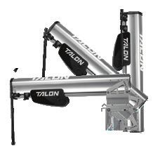
INTRODUCTION

  THANK YOU
  Thank you for purchasing the Talon Foot Switch. Intuitive features and wireless control lets you easily raise and lower the Talon spike.
  Control up to two Talons – independently or simultaneously – from this Bluetooth® enabled waterproof switch. Hands free control lets
  you focus on fishing.

  REGISTRATION
  Remember to keep your receipt and immediately register your
  Talon Foot Switch. To receive all the benefits of your product
  warranty please fill out and mail the registration card. You may
  also register your product online at minnkotamotors.com.

  SERIAL NUMBER
  Your Minn Kota 11-character serial number is very important. It
  helps to determine the specific model and year of manufacture.
  When contacting Consumer Service or registering your product,
  you will need to know your product’s serial number. We
  recommend that you write the serial number down so that you
  have it available for future reference.

                                                                                             EXAMPLE
         NOTICE: The serial number on your Talon Foot Switch is
         located on the reverse side of the switch from the buttons.
                                                                              SER NO S365 MK12345
         If the Foot Switch is attached to the Pedestal, remove the
         Foot Switch from the Pedestal to see the serial number.

  TALON FOOT SWITCH INFORMATION (For Consumer Reference Only)
  Model:___________________________________________________________________________________________________________________

  Serial Number:___________________________________________________________________________________________________________

  Purchase Date:___________________________________________________________________________________________________________

  Store Where Purchased:____________________________________________________________________________________________________

         NOTICE: Do not return your Talon Foot Switch to your retailer. Your retailer is not authorized to repair or replace this unit. You
         may obtain service by calling Minn Kota at (800) 227-6433 or returning your Talon Foot Switch to the Minn Kota Factory Service
         Center. Please include proof of purchase, serial number and purchase date for warranty service.

2 | minnkotamotors.com                                                                                      ©2018 Johnson Outdoors Marine Electronics, Inc.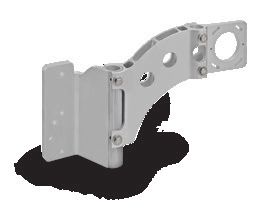
SAFETY CONSIDERATIONS

   Please thoroughly read the user manual. Follow all instructions and heed all safety considerations. Use of this product is only permitted
   for persons that have read and understood these instructions. Minors may use this product only under adult supervision.

                                                         WARNING
   You are responsible for the safe and prudent operation of your boat or vessel, and Talon(s). This product does not relieve you from the
   responsibility of safe operation of your boat. It may be hazardous to operate your Talon in rough or turbulent water conditions, such
   as fast currents or changing environmental conditions. Do not deploy your Talon if these conditions are present, especially when the
   underwater topography is unknown. Failure to follow this warning may result in unexpected operation or failure of the Talon to operate
   or anchor and could cause death or serious injury. You must avoid hazards to anchoring and always maintain a permanent watch so you
   can maintain proper control of your boat. You must always be prepared to regain manual control of your boat. Learn to operate your
   Minn Kota product in an area free from hazards and obstacles.

                                                         WARNING
   The Talon should be disconnected from the power source when it is not in use or is off the water. Always disconnect the Talon from
   battery(s) before cleaning or checking the Talon. In the event of unexpected operation, remove power leads from the battery.

                                                         WARNING
   Take care that neither you nor other persons approach the Talon Spike too closely while operating, neither with body parts nor with
   objects. The Talon is powerful and may endanger or injure you or others. While the Talon is operating, watch out for persons swimming
   and for floating objects. Persons who lack the ability to run the Talon or whose reactions are impaired by alcohol, drugs, medication, or
   other substances are not permitted to use this product.

                                                          CAUTION
   Never leave the boat unattended with the Talon as your only boat anchor. Talon is not intended to provide primary anchorage.

                                                         WARNING
   It is recommended to only use Johnson Outdoors approved accessories with your Talon. Using non-approved accessories including
   those used to mount or control your product may cause damage, unexpected operation and injury. Be sure to use the product and
   all approved accessories, including remotes, safely and in the manner directed to avoid accidental or unexpected operation. Keep
   all factory installed parts in place including motor, electronic and accessory covers, enclosures and guards. Failure to adhere to this
   warning may affect your warranty.

©2018 Johnson Outdoors Marine Electronics, Inc.                                                                             minnkotamotors.com | 3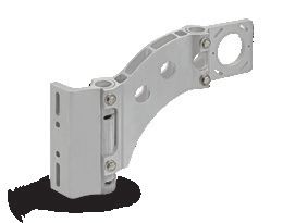
FEATURES

                                                                                              Talon Selection Indicator LEDs

                         Anchor Mode
                         Selection LED
                                                                                              Talon Selection Button /
                                                                                                 Work Light Button

                    Auto Up Button/
                     Pairing Button                                                              Auto Down
                                               Anchor                                           Button/Pairing
                                             Mode Button                                           Button

         NOTE: Specifications subject to change without notice. This diagram is for reference only and may differ from your
         actual Foot Switch.

4 | minnkotamotors.com                                                                            ©2018 Johnson Outdoors Marine Electronics, Inc.
INSTALLATION
INSTALLING THE TALON FOOT SWITCH
Your new Talon Foot Switch comes complete with all of the hardware you’ll need to install it directly to the deck of your boat. Please
review the parts list, mounting considerations and tools needed for installation prior to getting started.
INSTALLATION PARTS LIST
Item / Part # Description Qty.
Assembly
A 2994153 ASSEMBLY, TALON 3 FT SWITCH 1
2 2383455 SCREW-#8 X 1.0" PPH TY AB SS 3
4 s QUICK REFERENCE GUIDE 1
6 s INSTALLATION INSTRUCTIONS 1 A
2
✖ This part is included in an assembly and cannot be ordered individually.
s Not shown on Parts Diagram.
MOUNTING CONSIDERATIONS
Before mounting your Talon Foot Switch, please give consideration to the following:
1. Examine your boat to ensure that you will not drill into any obstructions and that the hardware will be accessible for assembly.
2. Make sure the area under the mounting location is flat, clear to drill holes and that the installation hardware will not damage
existing components below the mounting surface. It may be necessary to shim or modify the mounting surface under the mounting
location to create a flat area for the Foot Switch Pedestal to be mounted.
3. Mount the Talon Foot Switch in an area that has a clear line of communication with the Bluetooth enabled Talon(s) it is intended to
control for optimum performance.
4. Mount the Talon Foot Switch in an area where it will not become a tripping hazard.
TOOLS AND RESOURCES REQUIRED
• Pencil or similar marking tool • #2 Phillips Driving Bit
• Drill
©2018 Johnson Outdoors Marine Electronics, Inc. minnkotamotors.com | 5Installing the Foot Switch
INSTALLATION
Installing the Foot Switch
1 ITEM(S) NEEDED
#A x 1
a. Review the Mounting Considerations to determine
an acceptable mounting location. Once a location
is selected, take the Talon Foot Switch Assembly
(Item #A) and remove the Pedestal from the Base by
squeezing the Tabs on both sides of the Foot Pedal
and pulling the Foot Switch and Pedestal apart. Foot Switch
Tab
NOTICE: The Pedestal comes attached to
Tab
the Foot Switch and needs to be removed for
installation.
Pedestal
2 b. The Pedestal has three Mounting Holes that are
used to secure it to the boat. The bottom side of the Marked Location
Pedestal has three Pads around the Mounting Holes. Pedestal (top)
These Pads should be placed down, towards the boat Mounting Holes
when the Pedestal is installed. Position the Pedestal
at the selected location and mark the Mounting
Holes with a pencil or similar marking tool.
Pads
Pedestal (bottom)
6 | minnkotamotors.com ©2018 Johnson Outdoors Marine Electronics, Inc.Installing the Foot Switch
3 ITEM(S) NEEDED
#2 x 3
c. Double check the Mounting Location. Take the
Screws (Item #2) and place one each in the
Mounting Holes of the Pedestal. Make sure the Screws
Pedestal
Mounting Holes line up with the Marked Locations
and then use a Drill with #2 Phillips Driving Bit to
secure the Pedestal to the Deck of the Boat. Do not
over-tighten.
Mounting Holes
Deck of Boat
4 d. Once the Pedestal is installed, take the Foot Switch
and reattach it to the Pedestal. Make sure the Tabs Foot
on the Foot Switch click into place and the Foot Switch
Switch is fully seated on the Deck of the Boat.
Tab Tab
Deck of Boat
Pedestal
©2018 Johnson Outdoors Marine Electronics, Inc. minnkotamotors.com | 7Installing the Foot Switch
Pairing a Foot Switch to a Single Talon
1 a. Retract the anchor on the Talon by pressing the Up
button on the Talon Indicator Panel.
1a
Up Button
b. Once the Talon is fully retracted, press and hold the
Up button and the Down button on the Foot
Indicator
Switch at the same time until all of the LED's at the Down Button Panel
top of the Foot Switch begin to scroll. Then release
them.
c. Immediately press and hold the Up button Talon Selection
Anchor Mode Indicator LEDs
and the Down button simultaneously on the Selection LED
Indicator Panel. The Depth Indication LEDs on the Auto Down
Indicator Panel of the Talon will begin to scroll. Once Auto Up Button/ Button/Pairing
Pairing Button Button
the LEDs are scrolling release the buttons on the
Indicator Panel. The Talon and Foot Switch will go
into Pairing Mode for 20 seconds. If a signal with
three fast beeps occurs, the Talon and Foot Switch
have successfully paired. If 20 seconds pass while
in Pairing Mode and they do not successfully pair, an Talon Foot Switch
error tone will sound indicating that the pairing was
not successful, and the Foot Switch will not be able
to control the Talon.
d. If the Pair is unsuccessful, repeat the process.
Pairing a Foot Switch to Two Talons
In order to Pair a Foot Switch to the Talon, please be sure to first
Pair the Talons together. When two Bluetooth Talons are paired NOTICE: For instructions on how to pair two Talons and
together, the Foot Switch that was paired to an individual Talon assign their Port and/or Starboard mounting locations,
will operate both Talons. Please see the "Pairing Two Talons and please refer to your Talon owners manual.
Programming the Mounting Location" section of the Talon Owner's
Manual. If the two Talons are already paired together, a Foot Switch can be paired to either Talon. When the pairing process is
complete, the Foot Switch will be able to control both Talons.
8 | minnkotamotors.com ©2018 Johnson Outdoors Marine Electronics, Inc.USING THE FOOT SWITCH
CONTROLLING THE TALON WITH THE FOOT SWITCH
Talon Selection Indicator LEDs
Anchor Mode
Selection LED
Anchor
Mode Button
Talon Selection Button/
Work Light Button
Auto Down
Button/Pairing
Auto Up Button/ Button
Pairing Button
Anchor Mode Button Talon Selection Indicator LEDs
Used to select between Standard Mode, Soft When 2 Talons are paired in the system, the right
Bottom Mode and Rough Water Mode. LED is lit when the Starboard Talon is selected and
the left LED is lit when the Port Talon is selected.
Auto Up/Auto Down Buttons Both the right and left arrows are lit when both
& Pairing Buttons Talons are selected. When only one Talon is paired,
the lights will toggle, but the selection will control
Used to deploy, retract or pause the anchor on the the only paired Talon. When a selection is made, the
Talon. Also used to pair the Remote to a Talon. LEDs will stay lit for 1 second and then turn off.
Talon Selection Button / Anchor Mode Selection LED
Work Light Button The Center LED flashes red and green and then turns
Used to select the Port, Starboard, or both Talons. off for Standard Mode. The center LED will be lit
Used to toggle the Work Light "on" and "off" and green for Soft Bottom Mode and lit red for Rough
switch between the different Work Light colors and Water Mode. When in Soft Bottom Mode and Rough
intensities. Water Mode, the LED will stay lit for 1 second and
then turn off.
©2018 Johnson Outdoors Marine Electronics, Inc. minnkotamotors.com | 9USING THE FOOT SWITCH
Selecting a Talon to Operate with the Foot Switch
The Talon Selection button toggles the Talon that the Foot Switch is controlling, when 2 Talons are installed on the boat. The
selection toggles between a Talon mounted on the Port or Starboard side of the boat, or it can control both Talons at the same time.
The Talon Selection Indicator LED's are lit based on the selection made.
1 a. To toggle the Talon selected, press the Talon
Selection button, repeatedly until the desired
Talon Selection
Indicator LEDs
Talon is selected.
Port Starboard Talon
b. When the button is pressed, one or both of the Selection
Button
Talon Selection Indicator LEDs will be lit. If the
Foot Switch is oriented so the LEDs are facing away
from you, the arrow on the right will be lit when the
Starboard Talon is selected. If the arrow on the left is
lit, the Port Talon is selected. If both arrows are lit,
both Talons are selected.
Talon Foot Switch
NOTICE: When two Talons are paired to the Foot
Switch, it is possible to control them individually. NOTICE: The Talon will always remember the last
Therefore, the Talons may be in different states of selection made unless the Talon loses power.
deployment.
10 | minnkotamotors.com ©2018 Johnson Outdoors Marine Electronics, Inc.USING THE FOOT SWITCH
Deploy the Talon from the Foot Switch
Use the buttons on the Foot Switch to deploy the Talon anchor.
1 a. To deploy the Talon, double press the Down
button on the Foot Switch.
b. While the anchor is deploying, the action can be Auto Up Button/
Pairing Button Auto Down
paused on the Foot Switch by pressing either the
Button/Pairing
Down button or Up button again. Button
c. The paused deployment can be resumed by double
pressing the Down button again.
d. Once the deploying anchor gets to its full length of
travel or comes in contact with the bottom, it will go Talon Foot Switch
through an anchoring sequence determined by the
current Mode and then stop.
NOTICE: You do not need to hold the button to keep
the Talon deploying. The Talon will automatically continue
NOTICE: When two Talons are paired, the anchor
to deploy when the button is double pressed until it has
of the selected Talon will deploy. The selection can
reached its full deployment, received input to stop or
be Port, Starboard, or both.
anchors to the bottom.
WARNING
Take care that neither you nor other persons approach the Talon too closely, while operating, neither with body parts nor with
objects. The Talon is powerful and may endanger or injure you or others. While the Talon is operating, watch out for persons
swimming and for floating objects. Persons who lack the ability to run the Talon or whose reactions are impaired by alcohol, drugs,
medication, or other substances are not permitted to use this product.
©2018 Johnson Outdoors Marine Electronics, Inc. minnkotamotors.com | 11USING THE FOOT SWITCH
Retracting the Talon from the Foot Switch
Use the buttons on the Foot Switch to retract the Talon anchor.
1 a. To retract the Talon, press the Up
Foot Switch.
button on the
b. While the anchor is retracting, the action can be Auto Up Button/
Pairing Button Auto Down
paused on the Foot Switch by pressing either the Up Button/Pairing
button or the Down button. Button
c. The paused retraction can be resumed by pressing
the Up button again.
d. Once the retracting anchor on the Talon gets to its
full retraction it will stop. If the Talon is already fully Talon Foot Switch
retracted and the Up button is pressed again, an
error tone will sound.
NOTICE: You do not need to press and hold the button
to keep the anchor retracting. The Talon will automatically
NOTICE: When two Talons are paired, the anchor
continue to retract when the button is pressed until the
of the Talon selected on the Foot Switch will
Talon is either fully retracted or receives input to stop.
retract. The selection can be Port, Starboard, or
both.
CAUTION
Be sure that the Talon is clear of obstructions and persons
while retracting. The spaces between the 3 stages of the Talons
can create a pinch point. Do not come in contact with the Talon
while it is retracting to avoid the pinch point.
12 | minnkotamotors.com ©2018 Johnson Outdoors Marine Electronics, Inc.USING THE FOOT SWITCH
Toggle the Mode from the Foot Switch
Toggle the Mode on the Foot Switch when the water or anchoring conditions change to fit your anchoring needs.
1 a. The Mode can be toggled from the Foot Switch by
selecting the Anchor Mode button. The Anchor
Mode Selection LED displays the Mode that the
Anchor
Talon is currently set to. Press the Anchor Mode Mode Button Anchor Mode
button to toggle to the desired Mode. Selection LED
b. When the Talon is put in Standard mode, the LED
will flash red and green and then turn off. When the
LED is Green, the Talon is in Soft Bottom Mode.
When the LED is Red, the Talon is in Rough Water
Talon Foot Switch
Mode.
NOTICE: When the Talon is paired with a second
Talon, pressing the Anchor Mode button on the
Talon will toggle the Mode for both Talons.
Control the Work Light with the Foot Switch
The Work Light at the top of the Talon can be either white or blue and toggled between high, medium, or low intensities.
1 a. To Toggle the Work Light "on", press and hold the
Talon Selection button until the Work Light on Talon Selection Button/
the top of the Talon turns "on". Work Light Button
b. Continue to press the Talon Selection button on
the Foot Switch again before 5 seconds passes until
the desired color and intensity is selected.
c. To toggle the Work Light "off" press and hold the
Talon Selection button again until the Work Light
turns "off". Talon Foot Switch
NOTICE: When the Talon is paired with a second
Talon, pressing and holding the Talon Selection
WARNING
button will toggle the light for both Talons. The six The Work Light on the Talon is not intended for navigational
intensities for the Work Light are white high, white purposes. The Work Light does not replace or act as a
medium, white low, blue high, blue medium and substitute for proper navigation lighting of your vessel. Failure
blue low. to properly light your boat may cause harm or serious injury.
©2018 Johnson Outdoors Marine Electronics, Inc. minnkotamotors.com | 13SERVICE & MAINTENANCE
CAUTION
Before beginning any maintenance work, disconnect the Talon from the battery or if connected to a battery selector switch or power
disconnect switch, make sure that it is turned to the "off" position. Failure to disconnect power during maintenance work may result in
shock, unexpected operation and/or injury. Minn Kota recommends having the Talon serviced by an qualified marine technician at an
Authorized Service Center.
REPLACING THE REMOTE BATTERY
TOOLS AND RESOURCES REQUIRED
• Large Coin
INSTALLATION
1 a. Make sure your hands are clean, dry and static free.
Temporarily ground yourself by touching a grounded
1b
metal object in order to discharge any static
electricity in your body. Foot
Switch
CAUTION
Back
Static electricity can cause damage to the circuit board.
Discharge any static electricity by touching a metal object
that is grounded before beginning the remote battery
replacement.
b. With the back of the Foot Switch facing you,
use a large coin to rotate the Battery Cover
counterclockwise until the Battery Cover loosens and Battery
cannot be turned any further counterclockwise. Cover
NOTICE: The battery for the Foot Switch may be
replaced with, or without the Pedestal attached.
14 | minnkotamotors.com ©2018 Johnson Outdoors Marine Electronics, Inc.REPLACING THE REMOTE BATTERY
2 c. Remove the Battery Cover and the old battery.
Replace the battery with a new CR2450 coin cell
Battery
Cover
battery. Note the proper polarity of the battery.
Foot Switch Back O-ring
NOTICE: The replacement battery must be
a model CR2450 coin cell type. It is strongly Battery
recommended that a high quality battery is used.
The positive (+) of the battery should be facing
towards the Battery Cover.
3 d. Ensure the rubber O-ring is properly seated in the
underside of the Battery Cover.
3e Tab Foot Switch
Align
e. Replace the Battery Cover by aligning either of the
Unlock icons with the Tabs, and pressing the cover
down.
Lock Icon
Battery
f. Rotate the Battery Cover clockwise using the large Cover
coin until the Lock Icon aligns with the Tabs.
3d Unlock
Unlock Icon
Icon Battery
Cover
O-ring
Battery
Tab Lock Icon
Tab
Tab
Foot Switch
©2018 Johnson Outdoors Marine Electronics, Inc. minnkotamotors.com | 15Pairing a Foot Switch to a Single Talon
CLEARING PAIRED TALONS FROM THE FOOT SWITCH
The Foot Switch was designed so that all paired Talons can be cleared from memory.
1 a. Press and hold the Up button and the Down
button on the Foot Switch at the same time until all
Anchor Mode
Talon Selection
Selection LED
of the LED's at the top of the Foot Switch begin to Indicator LEDs
Auto Down
scroll. Then release the buttons. The Foot Switch will Button/Pairing
Auto Up Button/
go into Pairing Mode for 20 seconds. Once Pairing Pairing Button Button
times out all Talons will be cleared.
NOTICE: Putting the Foot Switch into Pairing
Mode, even if it is accidental, without Pairing the
Foot Switch to a Talon will clear all paired Talons. Talon Foot Switch
16 | minnkotamotors.com ©2018 Johnson Outdoors Marine Electronics, Inc.Troubleshooting and Repair
TROUBLESHOOTING AND REPAIR
We offer several options to help you troubleshoot and/or repair your product. Please read through the options listed below.
Buy Parts Online
You can buy parts on-line directly from our website at minnkotamotors.com. Orders confirmed by 12 Noon Central Time, with
Overnight Shipping selected, should ship the same business day if the parts are in stock. All other orders should ship within the
next 3 business days, depending on the shipment method chosen, and if the parts are in stock.
Frequently Asked Questions
We have FAQs available on our website to help answer all of your Minn Kota questions. Visit minnkotamotors.com and click on
“Frequently Asked Questions” to find an answer to your question.
Call Us (for U.S. and Canada)
Our consumer service representatives are available Monday – Friday between 7:00 a.m. – 4:30 p.m. CST at 800-227-6433. If you
are calling to order parts, please have the 11-character serial number from your product, specific part numbers, and credit card
information available. This will help expedite your call and allow us to provide you with the best consumer service possible. You can
reference the parts list located in your manual to identify the specific part numbers.
Email Us
You can email our consumer service department with questions regarding your Minn Kota products. To email your question, visit
minnkotamotors.com and click on “Support”.
Authorized Service Centers
Minn Kota has over 800 authorized service providers in the
United States and Canada where you can purchase parts or NOTICE: There are no serviceable components inside
get your products repaired. Please visit our Authorized the Talon Foot Switch.
Service Center page on our website to locate a service
provider in your area.
Scan to visit Minn
Kota service online.
©2018 Johnson Outdoors Marine Electronics, Inc. minnkotamotors.com | 17Compliance statements
ENVIRONMENTAL COMPLIANCE STATEMENT
It is the intention of JOME to be a responsible corporate citizen, operating in compliance with known and applicable environmental
regulations, and a good neighbor in the communities where we make or sell our products.
WEEE DIRECTIVE
EU Directive 2002/96/EC “Waste of Electrical and Electronic Equipment Directive (WEEE)” impacts most distributors, sellers, and
manufacturers of consumer electronics in the European Union. The WEEE Directive requires the producer of consumer electronics to
take responsibility for the management of waste from their products to achieve environmentally responsible disposal during the product
life cycle.
WEEE compliance may not be required in your location for electrical & electronic equipment (EEE), nor may it be required for EEE
designed and intended as fixed or temporary installation in transportation vehicles such as automobiles, aircraft, and boats. In some
European Union member states, these vehicles are considered outside of the scope of the Directive, and EEE for those
applications can be considered excluded from the WEEE Directive requirement.
This symbol (WEEE wheelie bin) on product indicates the product must not be disposed of with other household
refuse. It must be disposed of and collected for recycling and recovery of waste EEE. Johnson Outdoors Inc. will mark
all EEE products in accordance with the WEEE Directive. It is our goal to comply in the collection, treatment, recovery,
and environmentally sound disposal of those products; however, these requirements do vary within European Union
member states. For more information about where you should dispose of your waste equipment for recycling and
recovery and/or your European Union member state requirements, please contact your dealer or distributor from which
your product was purchased.
DISPOSAL
Minn Kota Talons are not subject to the disposal regulations EAG-VO (electric devices directive) that implements the WEEE directive.
Nevertheless never dispose of your Minn Kota Talon in a garbage bin but at the proper place of collection of your local town council.
Never dispose of battery in a garbage bin. Comply with the disposal directions of the manufacturer or his representative and dispose of
them at the proper place of collection of your local town council.
REGULATORY COMPLIANCE INFORMATION
Talon Foot Switch
FOOT SWITCH : 2994153
• Contains IC: 5123A-BGTBLE121LR
• Contains FCC ID: QOQBLE121LR
18 | minnkotamotors.com ©2018 Johnson Outdoors Marine Electronics, Inc.Compliance statements
FCC COMPLIANCE
This device complies with Part 15 of the FCC rules. Operation is subject to the following two conditions:
1. his device may not cause harmful interference.
T
2. This device must accept any interference that may be received, including interference that may cause undesired operation.
Changes or modifications not expressly approved by Johnson Outdoors Marine Electronics, Inc. could void the user’s authority to
operate this equipment.
NOTICE: This equipment has been tested and found to comply with the limits for a Class B digital device, pursuant to part
15 of the FCC Rules. These limits are designed to provide reasonable protection against harmful interference in a residential
installation. This equipment generates, uses and can radiate radio frequency energy and, if not installed and used in accordance
with the instructions, may cause harmful interference to radio communications. However, there is no guarantee that interference
will not occur in a particular installation. If this equipment does cause harmful interference to radio or television reception, which
can be determined by turning the equipment off and on, the user is encouraged to try to correct the interference by one or more of the
following measures:
• eorient or relocate the receiving antenna.
R
• Increase the separation between the equipment and receiver.
• Connect the equipment into an outlet on a circuit different from that to which the receiver is connected.
• Consult the dealer or an experienced radio/TV technician for help.
INDUSTRY CANADA COMPLIANCE
This product meets the applicable Industry Canada technical specifications. Operation is subject to the following two conditions:
(1) this device may not cause interference, and (2) this device must accept any interference, including interference that may cause
undesired operation of the device.
Changes or modifications not expressly approved by Johnson Outdoors Marine Electronics, Inc. could void the user’s authority to
operate this equipment.
ENVIRONMENTAL RATINGS
Ambient operating temperature range: -10C to 50C
Ambient operating humidity range: 5% to 95%
Maximum operating altitude: 10,000 feet
RADIO OPERATION TRADEMARKS
CONTROLLER
Minn Kota®, i-Pilot® and i-Pilot® Link™ are trademarked by or
• Frequency band: 2402 MHz to 2480 MHz registered trademarks of Johnson Outdoors Marine Electronics,
Inc.
• Maximum RF power transmitted: +10 dBm
FOOT SWITCH The Bluetooth® word mark and logos are registered trademarks
owned by Bluetooth SIG, Inc. and any use of such marks by
• Frequency band: 2402 MHz to 2480 MHz Johnson Outdoors Inc is under license. Other trademarks and
• Maximum RF power transmitted: +10 dBm trade names are those of their respective owners.
CE MASTER USER MANUAL (FOR CE CERTIFIED MODELS)
©2018 Johnson Outdoors Marine Electronics, Inc. minnkotamotors.com | 19PARTS DIAGRAM & PARTS LIST
TALON FOOT SWITCH
The parts diagram and parts list provides Minn Kota® WEEE compliance disassembly instructions. For more information about where
you should dispose of your waste equipment for recycling and recovery and/or your European Union member state requirements, please
contact your dealer or distributor from which your product was purchased. Tools required, but not limited to: flat head screwdriver,
Phillips screwdriver, socket set, pliers, wire cutters.
Talon Foot Switch Parts Diagram
22
28
14
8
10
A
6
2
12
24
B
20
26
16
4
18
20 | minnkotamotors.com ©2018 Johnson Outdoors Marine Electronics, Inc.PARTS DIAGRAM & PARTS LIST
Talon Foot Switch Parts List
Assembly Part # Description Quantity
A 2994153 ASSEMBLY,TALON 3 FT SWITCH 1
B 2886422 COVER, BATTERY COMPARTMENT ASY 1
Item Part # Description Quantity
2 ✖ BATTERY CR2450 1
4 ✖ WASHER-RUBBER,W/ADHESIVE 3
6 ✖ SCREW-2.5MMX8MM DELTA PT TORX 10
8 ✖ PCB ASM,FT. SWITCH,TALON 3 1
10 ✖ BOTTOM, TALON FOOT SWITCH 1
12 ✖ PAD-FOAM, I-PILOT 1.5 1
14 ✖ KEYPAD, TALON 3 FT SWITCH 1
16 ✖ DECAL, SERIAL NUMBER 1
18 ✖ DECAL, STANDARDS INFO 1
20 ✖ COVER, BATTERY COMPRT(SUB) 1
22 ✖ TOP, TALON 3 FT SWITCH 1
24 ✖ GASKET,BATTERY COMPARTMENT 1
26 2378845 PEDESTAL,TALON FOOT SWITCH 1
28 2383455 SCREW-#8 X 1.0" PPH TY AB SS 3
s 2374943 QCK REF GUIDE, FT SWITCH BT 1
s 2377172 MANUAL, TALON FOOT SWITCH BT 1
✖ This part is included in an assembly and cannot be ordered individually.
s Not shown on Parts Diagram.
©2018 Johnson Outdoors Marine Electronics, Inc. minnkotamotors.com | 21RECOMMENDED ACCESSORIES
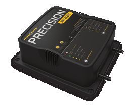
ON-BOARD & PORTABLE BATTERY CHARGERS
Stop buying new batteries and start taking care of the ones you’ve got. An inaccurate charger can actually damage your battery
over time – creating shorter run times and shorter overall life. Digitally controlled Minn Kota chargers are designed to provide a
fast and precise charge that protect and extend battery life.
MK212PC MK210D MK110PD
TALON ACCESSORIES
UNIVERSAL MODUL AR ADAP TER BR ACKETS
It’s easy to choose your bracket, easy to install it and pretty much impossible for anything to stop it. Talon’s Universal
Modular Adapter Brackets are built stronger than they have to be, and their innovative modular design lets you put
Talon in just the right position on your boat.
Unparalleled Strength Universal Modular Design
We built Talon with uncompromising power. And we built the Two brackets. Any transom. The universal design fits any situation, and the
brackets the exact same way. Made with extruded aluminum and brackets can be adjusted and tweaked to the perfect orientation. Two pivot
reinforced with rugged construction, our brackets hold Talon steady points let you adjust Talon to the perfect orientation (based on your transom
whether you’re trailering or tearing through heavy chop. style, outboard location and other factors). Once it’s in position, interlocking
teeth clamp down to lock it into place.
Jack Plate Sandwich-Style
Adapter Bracket Adapter Bracket
1810340
1810303
TALON TILT BR ACKET
This marine-grade, anodized aluminum tilt bracket
accommodates for low-clearance areas and boat
storage. Features adjustable deck support for added
stability while tilting.
1810222
Minn Kota Consumer & Technical Service 121 Power Drive
Johnson Outdoors Marine Electronics, Inc. Mankato, MN 56001
PO Box 8129 Phone (800) 227-6433 A Johnson Outdoors Company
©2018 Johnson Outdoors Marine Electronics, Inc.
minnkotamotors.com Mankato, MN 56001 Fax (800) 527-4464 All rights reserved.
Part #2377172 ECN 38526 Rev B 04/18COMMUTATEUR AU PIED POUR
Manuel du propriétaire
Compatible avec les tous systèmes BluetoothMD activés par Talon.PRÉSENTATION
MERCI
Nous vous remercions d’avoir fait l’acquisition d’un commutateur au pied pour Talon. Des fonctions intuitives et un contrôle sans fil vous
permettent de lever et baisser facilement le pieu du Talon. Contrôle jusqu’à deux Talon, indépendamment ou simultanément, depuis ce
commutateur étanche activé par BluetoothMD. Le contrôle sans main vous permet de vous concentrer sur la pêche.
ENREGISTREMENT
N’oubliez pas de conserver votre reçu et d’enregistrer
immédiatement votre commutateur au pied pour Talon. Pour
recevoir tous les avantages de la garantie de votre produit,
veuillez remplir la carte d’enregistrement et la retourner par la
poste. Vous pouvez aussi enregistrer votre produit en ligne sur
minnkotamotors.com.
NUMÉRO DE SÉRIE
Le numéro de série à 11 caractères Minn Kota est très
important. Cela permet de déterminer le modèle spécifique et
l’année de fabrication. Lorsque vous contactez le service à la
clientèle ou que vous enregistrez votre article, vous aurez besoin
du numéro de série de votre article. Nous vous suggérons
d’écrire le numéro de série afin qu’il soit disponible à des fins EXEMPLE
de référence future.
SER NO S365 MK12345
AVIS : Le numéro de série sur votre commutateur au
pied pour Talon se trouve sur l’envers des boutons du
commutateur. Si le commutateur au pied est fixé au
piédestal, retirez le commutateur au pied du piédestal
pour voir le numéro de série.
INFORMATIONS SUR LE COMMUTATEUR AU PIED POUR TALON
(à des fins de référence par le client seulement)
Modèle:__________________________________________________________________________________________________________________
Numéro de série:__________________________________________________________________________________________________________
Date d’achat:_____________________________________________________________________________________________________________
Magasin où acheté:________________________________________________________________________________________________________
AVIS : Ne pas retourner votre commutateur au pied pour Talon au détaillant. Le détaillant n’est pas autorisé à réparer ou
à remplacer cet appareil. Vous pouvez obtenir du service en appelant Minn Kota au 800 227-6433 ou en retournant votre
commutateur au pied pour Talon au Centre de service agréé de Minn Kota. Pour obtenir un service au titre de la garantie, veuillez
inclure la preuve d’achat, le numéro de série et la date d’achat.
24 | minnkotamotors.com ©2018 Johnson Outdoors Marine Electronics, Inc.CONSIGNES DE SÉCURITÉ
Veuillez lire attentivement le manuel de l’utilisateur. Suivre toutes les instructions et respecter toutes les consignes de sécurité.
L’utilisation de cet article n’est autorisée que pour les personnes qui ont lu et compris ces instructions. Les mineurs peuvent utiliser ce
moteur uniquement sous la supervision d’un adulte.
AVERTISSEMENT
Vous seul êtes responsable de la navigation sécuritaire et prudente de votre bateau ou vaisseau et de vos Talons. Ce produit ne vous
exonère pas de la responsabilité de naviguer de façon sécuritaire avec votre bateau. Il peut être dangereux d’utiliser votre Talon dans
des conditions d’eaux agitées ou turbulentes, comme les courants rapides ou les conditions environnementales changeantes. Ne pas
déployer le Talon en ces conditions, surtout lorsque la topographie subaquatique est inconnue. Le défaut de suivre cet avertissement
pourrait entraîner un fonctionnement inattendu ou un défaut de fonctionnement du Talon ou de l’ancre, et pourrait entraîner la mort ou
une blessure grave. Vous devez éviter les dangers à l’ancrage et toujours assurer une surveillance permanente afin que vous puissiez
conserver le contrôle approprié de votre bateau. Vous devez toujours être prêt à reprendre le contrôle manuel de votre bateau. Apprenez
à utiliser votre Minn Kota dans une zone exempte de dangers et d’obstacles.
AVERTISSEMENT
Le Talon doit être déconnecté de la source d’alimentation lorsqu’il n’est pas utilisé ou lorsqu’il est hors de l’eau. Toujours déconnecter
le Talon des batteries avant le nettoyage ou la vérification. En cas d’opération imprévue, retirez les câbles d’alimentation à la batterie.
AVERTISSEMENT
Veillez à ce que ni vous ni d’autres personnes ne vous approchiez trop près du pieu du Talon, que ce soit seulement avec une partie du
corps ou des objets. Le Talon est puissant et pourrait provoquer des situations périlleuses ou des blessures, pour vous ou les autres.
Lorsque le Talon est en marche, être alerte pour les personnes qui nagent ou les objets flottants. Les personnes dont la capacité à faire
fonctionner le Talon est affaiblie par l’alcool, la drogue, les médicaments ou d’autres substances ne sont pas autorisées à utiliser ce
produit.
ATTENTION
Ne jamais laisser le bateau sans surveillance avec le Talon comme seule ancre. Le Talon n’est pas destiné à fournir l’ancrage principal.
AVERTISSEMENT
On recommande d’utiliser exclusivement les accessoires approuvés par Johnson Outdoors avec votre Talon. L’utilisation d’accessoires
non approuvés, y compris pour monter ou contrôler votre produit, pourrait causer des dommages, un fonctionnement inattendu et des
blessures. Veiller à utiliser le produit ainsi que les accessoires approuvés, y compris les télécommandes, en toute sécurité et de la
manière indiquée pour éviter un fonctionnement accidentel ou inattendu. Ne pas retirer les pièces installées en usine, y compris les
couvercles, boîtiers et protections du moteur et des électroniques et des accessoires. Le défaut de respecter cet avertissement pourrait
affecter la garantie.
©2018 Johnson Outdoors Marine Electronics, Inc. minnkotamotors.com | 25CARACTÉRISTIQUES
DEL d’indication de la
sélection pour Talon
DEL de sélection
du mode de l’ancre
Bouton Sélection du Talon/
Bouton Éclairage de travail
Bouton Up
(Montée) Bouton Down
automatique/ Bouton Mode de l’ancre (Descente)
Bouton Couplage automatique/
Bouton Couplage
AVIS : Les spécifications peuvent faire l’objet de modifications sans préavis. Ce schéma est fourni aux fins de référence
seulement et peut différer de votre commutateur au pied.
26 | minnkotamotors.com ©2018 Johnson Outdoors Marine Electronics, Inc.INSTALLATION
INSTALLATION DU COMMUTATEUR AU PIED POUR TALON
Votre nouveau commutateur au pied pour Talon est livré avec toute la quincaillerie qu’il vous faut pour l’installer directement sur le tableau
arrière de votre bateau. Avant de commencer, veuillez examiner la liste des pièces et des outils nécessaires à l’installation.
LISTE DE PIÈCES D’INSTALLATION
Article/ Nº de Description Qté
Assemblage Pièce
A 2994153 ASSEMBLY, TALON 3 FT SWITCH 1
2 2383455 SCREW-#8 X 1.0" PPH TY AB SS 3
4 s QUICK REFERENCE GUIDE 1
6 s INSTALLATION INSTRUCTIONS 1 A
2
✖ Cette pièce est incluse dans un ensemble et ne peut pas être commandée
individuellement.
s Non visible sur le schéma des pièces.
FACTEURS DE MONTAGE
Avant de monter votre commutateur au pied pour Talon, veuillez tenir compte de ce qui suit :
1. Examinez le bateau afin de s’assurer de ne pas percer une obstruction et que la quincaillerie sera accessible pour l’assemblage.
2. Assurez-vous que la zone sous l’emplacement d’installation est plate, qu’on peut y percer des trous et que la quincaillerie
d’installation n’endommagera pas de composantes en place sous la surface de montage. Il pourrait être nécessaire de caler
ou modifier la surface de montage sous l’emplacement de montage afin de créer une zone plate pour monter le piédestal du
commutateur au pied.
3. Pour une performance optimale, montez le commutateur au pied pour Talon dans une zone permettant d’avoir une ligne de
communication nette avec le ou les Talon activés par Bluetooth qu’il doit contrôler.
4. Montez le commutateur au pied pour Talon dans une zone où il n’y aura pas de risque de trébuchement.
OUTILS ET RESSOURCES NÉCESSAIRES
• Crayon ou autre outil de • Perceuse
marquage semblable • Mèche Phillips n° 2
©2018 Johnson Outdoors Marine Electronics, Inc. minnkotamotors.com | 27INSTALLATION DU TALON
INSTALLATION
Installation du commutateur au pied
1 ARTICLE(S) REQUIS
#A x 1
a. Relisez les facteurs de montage à tenir compte pour
déterminer un emplacement acceptable. Une fois
l’emplacement sélectionné, prenez l’ensemble du
commutateur au pied pour Talon (article n° A) et
retirez le piédestal de la base en serrant les onglets
sur chaque côté de la pédale et en séparant le Commutateur
commutateur au pied et le piédestal. au pied Onglet
Onglet
AVIS : Le piédestal est attaché au commutateur
au pied et doit être retiré pour l’installation.
Piédestal
2 b. Le piédestal comporte trois trous de montage
utilisés pour le fixer au bateau. La partie inférieure Emplacement marqué
du piédestal est dotée de trois coussinets autour Piédestal (dessus)
des trous de montage. Ces coussinets doivent être Trous de montage
posés en bas, vers le bateau lors de l’installation du
piédestal. Positionnez le piédestal à l’emplacement
sélectionné et marquez les trous de montage avec un
crayon ou un outil de marquage semblable.
Piédestal (bas) Coussinets
28 | minnkotamotors.com ©2018 Johnson Outdoors Marine Electronics, Inc.INSTALLATION DU TALON
3 ARTICLE(S) REQUIS
#2 x 3
c. Contre-vérifiez l’emplacement du montage. Prenez
les vis (article n° 2) et mettez-en une dans chaque
trou de montage du piédestal. Veuillez à l’alignement Vis
Piédestal
des trous de montage avec les emplacements
marqués puis utilisez une perceuse avec une mèche
Phillips n° 2 pour fixer le piédestal au pont du
bateau. Ne pas trop serrer.
Trous de montage
Pont du bateau
4 d. Une fois que le piédestal est installé, prenez le
commutateur au pied et rattachez-le au piédestal.
Veillez à ce que les onglets sur le commutateur au
pied s’enclenchent et que le commutateur au pied
repose bien sur le pont du bateau. Commutateur
au pied
Onglet
Onglet
Pont du Bateau
Piédestal
©2018 Johnson Outdoors Marine Electronics, Inc. minnkotamotors.com | 29INSTALLATION DU TALON
Couplage du commutateur au pied à un Talon unique
1 a. Rétractez l’ancre du Talon en appuyant sur le bouton
Up (Montée) sur le panneau indicateur du Talon.
1a
Bouton Up
(Montée)
b. Une fois le Talon entièrement rétracté, appuyez
simultanément sur le bouton Up (Montée) et le
bouton Down (Descente) du commutateur au Bouton Down Panneau
(Descente) indicateur
pied et gardez-les enfoncés jusqu’à ce que les DEL
sur le dessus du commutateur au pied se mettent à DEL
défiler. Relâchez ensuite les boutons. d’indication
DEL de sélection de la sélection
du mode de pour Talon
c. Immédiatement, appuyez simultanément sur l’ancre
Bouton Down
le bouton Up (Montée) et le bouton Down (Descente)
(Descente) sur le panneau indicateur et gardez- Bouton Up automatique/
(Montée) Bouton Couplage
les enfoncés. Les DEL d’indication de profondeur automatique /
sur le panneau indicateur du Talon commenceront Bouton Couplage
à défiler. Lorsque les DEL commencent à défiler,
relâchez les boutons sur le panneau indicateur.
Le Talon et le commutateur au pied passeront au
mode Couplage pendant 20 secondes. Si un signal Commutateur au
pied pour Talon
avec trois bips rapides se produit, le Talon et le
commutateur au pied ont été couplés avec succès.
Si 20 secondes s’écoulent en mode couplage, mais
que le couplage ne réussit pas, une tonalité d’erreur
retentira indiquant que le couplage n’a pas réussi et
que le commutateur au pied ne pourra contrôler le
Talon.
d. Si le couplage échoue, recommencez le processus.
Couplage d’un commutateur au pied à deux Talons
Afin de coupler un commutateur au pied à un Talon, assurez-vous
de coupler d’abord les Talons ensemble. Lorsque deux Talons AVIS : Pour obtenir des directives sur le couplage de
compatibles Bluetooth sont couplés, le commutateur au pied qui deux Talons et l’assignation de leurs emplacements de
était couplé à un Talon individuel fera fonctionner les deux Talons. montage à bâbord ou à tribord, veuillez consulter le
Veuillez consulter la section « Couplage de deux Talons et manuel du propriétaire Talon.
programmation de l’emplacement de montage » de ce manuel du
propriétaire Talon. Si les deux Talons sont déjà couplés, on peut coupler un commutateur au pied à un Talon ou à l’autre. Lorsque le
processus de couplage est terminé, le commutateur au pied peut contrôler les deux Talons.
30 | minnkotamotors.com ©2018 Johnson Outdoors Marine Electronics, Inc.UTILISATION DU COMMUTATEUR AU PIED
CONTRÔLE DU TALON AVEC LE COMMUTATEUR AU PIED
DEL d’indication de la
sélection pour Talon
DEL de sélection
du mode de l’ancre
Bouton Mode Bouton Sélection du Talon/
de l’ancre Bouton Éclairage de travail
Bouton Down
(Descente)
automatique/
Bouton Up Bouton Couplage
(Montée)
automatique /
Bouton Couplage
Bouton Mode de l’ancre DEL d’indication de la sélection
Sert à choisir entre le mode Standard, le mode
pour Talon
Fond mou et le mode Eaux agitées. Lorsque deux Talons sont couplés dans le système,
la DEL droite s’allume lorsque le Talon de tribord
Bouton Up (Montée) est sélectionné et la DEL gauche s’allume lorsque
automatique / Bouton Down le Talon de bâbord est sélectionné. Les flèches de
(Descente) automatique/ gauche et de droite sont allumées lorsque les deux
Bouton Couplage Talons sont sélectionnés. Lorsqu’un seul Talon est
couplé, les voyants clignoteront, mais la sélection
Servent à déployer, à rétracter ou à mettre en contrôlera le seul Talon couplé. Lors d’une sélection,
pause l’ancre du Talon. Servent également à les DEL resteront allumées pendant 1 seconde puis
coupler la télécommande à un Talon. s’éteindront.
Bouton Sélection du Talon / DEL de sélection du mode de
Bouton Éclairage de travail l’ancre
Servent à sélectionner le Talon de bâbord, de Pour le mode Standard, la DEL centrale clignote
tribord ou les deux. Servent à allumer et à éteindre en rouge et en vert, puis s’éteint. La DEL centrale
l’éclairage de travail et à modifier la couleur et s’allume en vert pour le mode Fond mou et en rouge
l’intensité de l’éclairage de travail. pour le mode Eaux agitées. En mode Fond mou et en
mode Eaux agitées, la DEL reste allumée pendant 1
seconde puis s’éteint.
©2018 Johnson Outdoors Marine Electronics, Inc. minnkotamotors.com | 31UTILISATION DU COMMUTATEUR AU PIED
Sélection d’un Talon à commander avec le commutateur au pied
Le bouton Sélection du Talon change le Talon contrôlé par le commutateur au pied, lorsque deux Talons sont installés sur le
bateau. La sélection passe entre un Talon monté du côté bâbord ou tribord du bateau, ou peut servir à contrôler les deux Talon à la
fois. Les DEL d’indication de sélection du Talon s’allument selon la sélection effectuée.
1 a. Pour changer le Talon sélectionné, appuyez sur le
bouton Sélection du Talon de manière répétée,
DEL d’indication de la
sélection pour Talon
jusqu’à ce que le Talon désiré soit sélectionné. Bâbord Tribord
Bouton
b. Lorsqu’on appuie sur le bouton, une des DEL Sélection
d’indication de sélection du Talon s’allumera. Si le du Talon
commutateur au pied est orienté de manière à ce
que les DEL soient vers vous, la flèche à la droite
s’allumera lorsqu’on sélectionne le Talon de tribord.
Si la flèche à la gauche est allumée, le Talon de
bâbord est sélectionné. Si les deux flèches sont
Commutateur au pied pour Talon
allumées, les deux Talons sont sélectionnés.
AVIS : Lorsque les deux Talons sont couplés AVIS : Le Talon se souviendra toujours de la dernière
au commutateur au pied, il est possible de les sélection effectuée à moins que l’alimentation du Talon ne
contrôler individuellement. Par conséquent, soit coupée.
les Talons peuvent être à différents stades de
déploiement.
32 | minnkotamotors.com ©2018 Johnson Outdoors Marine Electronics, Inc.UTILISATION DU COMMUTATEUR AU PIED
Déployer le Talon depuis le commutateur au pied
Utilisez les boutons du commutateur au pied pour déployer l’ancre Talon.
1 a. Pour déployer le Talon, appuyez deux fois sur le
bouton Down (Descente) sur le commutateur
Bouton Up
au pied. (Montée)
automatique / Bouton Down
b. Vous pouvez mettre en pause le déploiement de Bouton Couplage (Descente)
l’ancre grâce au commutateur au pied, soit en automatique/
Bouton Couplage
appuyant à nouveau sur le bouton Up (Montée) ,
soit en appuyant sur le bouton Down (Descente) .
c. Vous pouvez reprendre le déploiement mis en pause
en appuyant à nouveau deux fois sur le bouton Down
(Descente) . Commutateur au pied pour Talon
d. Lorsque l’ancre de déploiement atteint sa longueur
de déplacement totale ou touche le fond, elle AVIS : Vous n’avez pas à garder le bouton enfoncé pour
exécutera une séquence d’ancrage déterminée par le que le Talon continue à se déployer. Le Talon continuera
mode actuel, puis s’arrêtera. automatiquement à se déployer lorsqu’on appuie sur
le bouton, jusqu’à ce qu’il atteigne sa longueur de
déploiement totale, qu’il reçoive une commande d’arrêt ou
AVIS : Lorsque deux Talons sont couplés, l’ancre
qu’il termine l’ancrage au bas.
du Talon sélectionné s’affichera. La sélection peut
être bâbord, tribord ou les deux.
AVERTISSEMENT
Assurez-vous de garder tout objet ou partie du corps à distance du Talon pendant son fonctionnement. Le Talon est puissant et
pourrait provoquer des situations périlleuses ou des blessures, pour vous ou les autres. Lorsque le Talon est en marche, être alerte
pour les personnes qui nagent ou les objets flottants. Les personnes dont la capacité à faire fonctionner le Talon est affaiblie par
l’alcool, la drogue, les médicaments ou d’autres substances ne sont pas autorisées à utiliser ce produit.
©2018 Johnson Outdoors Marine Electronics, Inc. minnkotamotors.com | 33Installation de l’écran de déflexion d’eau
Rétracter le Talon du commutateur au pied
Utilisez les boutons du commutateur au pied pour rétracter l’ancre Talon.
1 a. Pour rétracter le Talon, appuyez sur le bouton Up
(Montée) du commutateur au pied. Bouton Up
(Montée)
b. Vous pouvez mettre en pause la rétraction de l’ancre automatique / Bouton Down
grâce au commutateur au pied, en appuyant soit Bouton Couplage (Descente)
automatique/
sur le bouton Up (Montée) ou le bouton Down Bouton Couplage
(Descente) .
c. Vous pouvez reprendre la rétraction mise en pause en
appuyant à nouveau sur le bouton Up (Montée) .
d. Lorsque l’ancre Talon sera entièrement rétractée, elle Commutateur au pied pour Talon
s’arrêtera. Si le Talon est déjà entièrement rétracté et
qu’on appuie à nouveau sur le bouton Up (Montée)
une tonalité d’erreur se fera entendre.
AVIS : Vous n’avez pas à garder le bouton enfoncé pour
que l’ancre continue à se rétracter. Le Talon continuera
à se rétracter automatiquement lorsqu’on appuie sur le
AVIS : Lors du couplage de deux Talons, l’ancre
bouton, jusqu’à ce qu’il soit entièrement rétracté ou qu’il
du Talon sélectionné sur le commutateur au pied
reçoive une commande d’arrêt.
sera rétractée. La sélection peut être bâbord,
tribord ou les deux.
ATTENTION
Assurez-vous que le Talon est à l’écart d’obstacles et de
personnes lors de la rétractation. Les espaces entre les 3
étages du Talon peuvent créer un point de pincement. Ne
touchez pas au Talon tandis qu’il se rétracte, afin d’éviter le
point de pincement.
34 | minnkotamotors.com ©2018 Johnson Outdoors Marine Electronics, Inc.Installation de l’écran de déflexion d’eau
Basculer le mode depuis le commutateur au pied
Changez le mode sur le commutateur au pied lorsque les conditions d’ancrage ou d’eau changent, afin de convenir à vos besoins d’ancrage.
1 a. On peut changer le mode grâce au commutateur au
pied en utilisant le bouton Mode de l’ancre . La
DEL de sélection du mode de l’ancre affiche le mode
Bouton Mode DEL de sélection
auquel le Talon est actuellement réglé. Appuyez sur de l’ancre du mode de l’ancre
le bouton Mode de l’ancre pour passer au mode
désiré.
b. Lorsque le Talon est mis en mode Standard, la
DEL clignotera en rouge et en vert, puis s’éteindra.
Lorsque la DEL est verte, le Talon est en Mode Fond
Commutateur au pied pour Talon
mou. Lorsque la DEL est rouge, le Talon est en
mode Eaux agitées.
AVIS : Lorsque le Talon est couplé à un autre Talon,
appuyer sur le bouton Mode de l’ancre du Talon
changera le mode pour les deux Talons.
Contrôler l’éclairage de travail avec le commutateur au pied
L’éclairage de travail en haut du Talon peut être de couleur blanche ou bleue et peut être réglé à une intensité élevée, moyenne ou faible.
1 a. Pour allumer l’éclairage de travail, appuyez sur le
bouton Sélection du Talon et gardez-le enfoncé Bouton Sélection
du Talon / Bouton
jusqu’à ce que l’éclairage de travail en haut du Talon Éclairage de travail
s’allume.
b. Appuyez à nouveau sur le bouton Sélection du
Talon sur le commutateur au pied avant que 5
secondes ne se soient écoulées, jusqu’à ce que la
couleur et l’intensité souhaitées soient sélectionnées.
Commutateur au pied pour Talon
c. Pour éteindre l’éclairage de travail, appuyez sur le
bouton Sélection du Talon et gardez-le enfoncé
jusqu’à ce que l’éclairage de travail en haut du Talon
s’éteigne.
AVERTISSEMENT
L’éclairage de travail du Talon n’est pas conçu à des fins
AVIS : Lorsque le Talon est couplé à un autre de navigation. Il ne doit pas remplacer un bon éclairage de
Talon, appuyez sur le bouton Sélection du Talon navigation de votre embarcation. Ne pas bien éclairer votre
et gardez-le enfoncé allumera ou éteindra bateau pourrait mener à des blessures graves.
l’éclairage pour les deux Talons. Les six intensités
de l’éclairage de travail sont blanche élevée,
blanche moyenne, blanche faible, bleue élevée,
bleue moyenne et bleue faible.
©2018 Johnson Outdoors Marine Electronics, Inc. minnkotamotors.com | 35You can also read