HPE Apollo 2000 Gen10 Chassis User Guide - HPE Support Center
←
→
Page content transcription
If your browser does not render page correctly, please read the page content below

HPE Apollo 2000 Gen10 Chassis User
Guide

Abstract
This document is for the person who installs, administers, and troubleshoots the system.
Hewlett Packard Enterprise assumes that you are qualified in the servicing of computer
equipment and trained in using safe practices when dealing with hazardous energy levels.

Part Number: 879112-005
Published: April 2019
Edition: 5
©   Copyright 2017-2019 Hewlett Packard Enterprise Development LP

Notices
         The information contained herein is subject to change without notice. The only warranties for Hewlett
         Packard Enterprise products and services are set forth in the express warranty statements accompanying
         such products and services. Nothing herein should be construed as constituting an additional warranty.
         Hewlett Packard Enterprise shall not be liable for technical or editorial errors or omissions contained
         herein.
         Confidential computer software. Valid license from Hewlett Packard Enterprise required for possession,
         use, or copying. Consistent with FAR 12.211 and 12.212, Commercial Computer Software, Computer
         Software Documentation, and Technical Data for Commercial Items are licensed to the U.S. Government
         under vendor's standard commercial license.
         Links to third-party websites take you outside the Hewlett Packard Enterprise website. Hewlett Packard
         Enterprise has no control over and is not responsible for information outside the Hewlett Packard
         Enterprise website.

Acknowledgments
         Intel®, Itanium®, Pentium®, Xeon®, Intel Inside®, and the Intel Inside logo are trademarks of Intel
         Corporation in the U.S. and other countries.
         Microsoft® and Windows® are either registered trademarks or trademarks of Microsoft Corporation in the
         United States and/or other countries.
         Adobe® and Acrobat® are trademarks of Adobe Systems Incorporated.
         Java® and Oracle® are registered trademarks of Oracle and/or its affiliates.
         UNIX® is a registered trademark of The Open Group.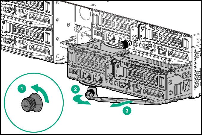
Contents

    HPE Apollo 2000 Gen10 System............................................................6
          Introduction................................................................................................................................... 6

    Planning the installation.........................................................................7
          Safety and regulatory compliance.................................................................................................7
          Product QuickSpecs......................................................................................................................7
          Configuration guidelines............................................................................................................... 7
          Determining power and cooling configurations............................................................................. 7
                 Power requirements........................................................................................................... 7
                 HPE Apollo Platform Manager........................................................................................... 7
                 Hot-plug power supply calculations....................................................................................8
          Compiling the documentation....................................................................................................... 8
          Warnings and cautions..................................................................................................................8
          Space and airflow requirements................................................................................................... 9
          Temperature requirements..........................................................................................................10
          Grounding requirements............................................................................................................. 10
          Connecting a DC power cable to a DC power source................................................................ 10

    Identifying components and LEDs...................................................... 12
          System components................................................................................................................... 12
          Front panel components............................................................................................................. 12
          Front panel LEDs........................................................................................................................ 14
          Power fault LEDs........................................................................................................................ 16
          Rear panel components..............................................................................................................17
          Power supply LED...................................................................................................................... 18
          Fan locations...............................................................................................................................19
          Drive bay numbering...................................................................................................................19
                 Drive bay mapping........................................................................................................... 24
          Hot-plug drive LED definitions.................................................................................................... 27
                 SmartDrive hot-plug drive LED definitions....................................................................... 27
                 Low-profile LFF hot-plug drive LED definitions................................................................ 28
                 NVMe SSD LED definitions..............................................................................................30
          RCM module............................................................................................................................... 31
                 RCM module components................................................................................................31
                 RCM module LEDs...........................................................................................................32

    Installing the chassis ...........................................................................33
          Installation overview....................................................................................................................33
          Unpacking the system.................................................................................................................33
          Preparing the chassis for installation.......................................................................................... 33
                  HPE Smart Storage Battery............................................................................................. 36
                  Installing the redundant fan option................................................................................... 42
          Installing the chassis into the rack.............................................................................................. 44
                  Installing the 2U rack rail kit............................................................................................. 45
          Installing hardware options into the server................................................................................. 48
          Installing the system components...............................................................................................48

                                                                                                                                                         3
Installing a server............................................................................................................. 48
                   Installing the server tray blank......................................................................................... 49
                   Installing a hot-plug AC power supply..............................................................................50
                   Installing a hot-plug DC power supply..............................................................................51
                   Drive options.................................................................................................................... 57
           Installing the optional 2U bezel................................................................................................... 61

    Cabling................................................................................................... 63
           Cabling guidelines.......................................................................................................................63
           Cabling the chassis.....................................................................................................................64
                 Front I/O cabling...............................................................................................................64
                 Drive backplane power cabling........................................................................................ 65
                 Fan power cabling............................................................................................................67
                 Fan module cabling for Standard Power Supply..............................................................68
                 Fan module cabling for HPE 2200W Flex Slot Platinum Hot Plug Low Halogen
                 Power Supply................................................................................................................... 68
                 Energy pack cabling.........................................................................................................69
                 RCM 2.0 cabling...............................................................................................................69
           Connecting the chassis to the network....................................................................................... 69
                 Installing the RCM module............................................................................................... 69
                 Connecting multiple chassis to the network with the RCM module iLO ports.................. 71
                 Connecting the optional HPE APM module..................................................................... 72
           Connecting power cables and applying power to the chassis.................................................... 73

    Configuring the system........................................................................ 74
           Power capping............................................................................................................................ 74
                 Power capping modes......................................................................................................74
           Configuring a power cap............................................................................................................. 75
                 Setting the chassis power cap mode with HPE APM.......................................................75

    Troubleshooting.................................................................................... 76
           NMI functionality..........................................................................................................................76
           Troubleshooting resources..........................................................................................................76

    Electrostatic discharge.........................................................................77
           Preventing electrostatic discharge.............................................................................................. 77
           Grounding methods to prevent electrostatic discharge...............................................................77

    Specifications........................................................................................78
           Environmental specifications...................................................................................................... 78
           Mechanical specifications........................................................................................................... 78
           Power supply specifications........................................................................................................79
                  HPE 800W Flex Slot Platinum Hot-plug Low Halogen Power Supply..............................80
                  HPE 800W Flex Slot Universal Hot-plug Low Halogen Power Supply.............................81
                  HPE 800W Flex Slot -48VDC Hot-plug Low Halogen Power Supply............................... 81
                  HPE 1600W Flex Slot Platinum Hot-plug Low Halogen Power Supply............................82
                  HPE 2200W Flex Slot Platinum Hot Plug Low Halogen Power Supply........................... 83
           Hot-plug power supply calculations............................................................................................ 84

    Websites................................................................................................ 85

4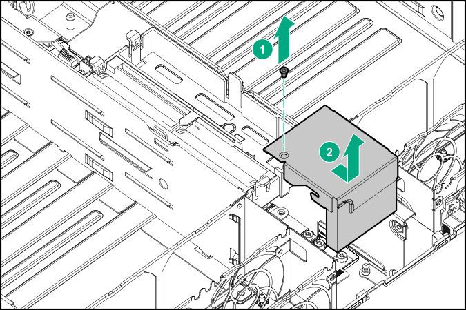
Support and other resources...............................................................86
      Accessing Hewlett Packard Enterprise Support......................................................................... 86
      Accessing updates......................................................................................................................86
      Customer self repair....................................................................................................................87
      Remote support.......................................................................................................................... 87
      Warranty information...................................................................................................................87
      Regulatory information................................................................................................................88
      Documentation feedback............................................................................................................ 88

Acronyms and abbreviations...............................................................89

                                                                                                                                               5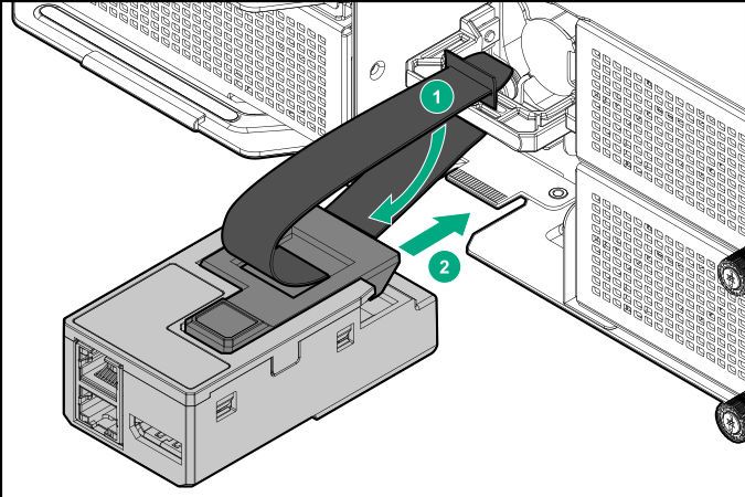
HPE Apollo 2000 Gen10 System
Introduction
       The HPE Apollo 2000 Gen10 System consists of a chassis and servers. There are four chassis options
       with different storage configurations. To ensure proper thermal cooling, all server tray slots on the chassis
       must be populated with servers or server tray blanks.
       Chassis

       •   HPE Apollo r2200 Gen10 Chassis (12 low-profile LFF model)
       •   HPE Apollo r2600 Gen10 Chassis (24 SFF model, supports a maximum of 24 SFF SmartDrives or a
           mix of 16 SFF SmartDrives and 8 NVMe drives)
       •   HPE Apollo r2800 Gen10 Chassis with 16 NVMe
       •   HPE Apollo r2800 Gen 10 Chassis (24 SFF model with storage expander backplane)

       Servers

       •   HPE ProLiant XL170r Gen10 Server (1U)
       •   HPE ProLiant XL190r Gen10 Server (2U)

       The chassis supports the combination of 1U and 2U servers. One chassis can support a maximum of the
       following:

       •   Four 1U servers
       •   Two 1U servers and one 2U server
       •   Two 2U servers

       For more information about product features, specifications, options, configurations, and compatibility, see
       the product QuickSpecs on the Hewlett Packard Enterprise website.

6   HPE Apollo 2000 Gen10 System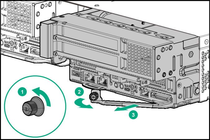
Planning the installation
Safety and regulatory compliance
    For important safety, environmental, and regulatory information, see Safety and Compliance Information
    for Server, Storage, Power, Networking, and Rack Products, available at the Hewlett Packard Enterprise
    website (http://www.hpe.com/support/Safety-Compliance-EnterpriseProducts).

Product QuickSpecs
    For more information about product features, specifications, options, configurations, and compatibility, see
    the product QuickSpecs on the Hewlett Packard Enterprise website (http://www.hpe.com/info/qs).

Configuration guidelines
    Operate the chassis only when a device or blank is installed in all device bays. Before powering up the
    chassis, be sure to do the following:

    •   Install a drive or drive blank into all drive bays.
    •   Install a server or a blank into all server bays.
    •   Install a power supply or power supply blank into all power supply bays.

Determining power and cooling configurations
    Validate power and cooling requirements based on location and installed components.

Power requirements
    Installation of this equipment must comply with local and regional electrical regulations governing the
    installation of IT equipment by licensed electricians. This equipment is designed to operate in installations
    covered by NFPA 70, 1999 Edition (National Electric Code) and NFPA-75, 1992 (code for Protection of
    Electronic Computer/Data Processing Equipment). For electrical power ratings on options, refer to the
    product rating label or the user documentation supplied with that option.

          WARNING: To reduce the risk of personal injury, fire, or damage to the equipment, do not overload
          the AC supply branch circuit that provides power to the rack. Consult the electrical authority having
          jurisdiction over wiring and installation requirements of your facility.

          CAUTION: Protect the server from power fluctuations and temporary interruptions with a regulating
          UPS. This device protects the hardware from damage caused by power surges and voltage spikes
          and keeps the server in operation during a power failure.

HPE Apollo Platform Manager
    HPE Apollo Platform Manager, formerly named HPE Advanced Power Manager, is a point of contact for
    system administration.
    To install, configure, and access HPE APM, see the HPE Apollo Platform Manager User Guide on the
    Hewlett Packard Enterprise website (http://www.hpe.com/support/APM_UG_en).

                                                                                    Planning the installation     7
Hot-plug power supply calculations
        For more information on the hot-plug power supply and calculators to determine server power
        consumption in various system configurations, see the Hewlett Packard Enterprise Power Advisor website
        (http://www.hpe.com/info/poweradvisor/online).

Compiling the documentation
        The documentation, while delivered individually and in various formats, works as a system. Consult these
        documents before attempting installation. These documents provide the required important safety
        information and decision-making steps for the configuration. To access these documents, see the Hewlett
        Packard Enterprise website (http://www.hpe.com/info/Apollo2000-docs).

Warnings and cautions
              WARNING: To reduce the risk of personal injury or damage to equipment, heed all warnings and
              cautions throughout the installation instructions.

              WARNING: To reduce the risk of personal injury or damage to the equipment, be sure that:
              •   The rack is bolted to the floor using the concrete anchor kit.
              •   The leveling feet extend to the floor.
              •   The full weight of the rack rests on the leveling feet.
              •   The racks are coupled together in multiple rack installations.
              •   Only one component is extended at a time. If more than one component is extended, a rack
                  might become unstable.

              WARNING: The chassis is very heavy. To reduce the risk of personal injury or damage to the
              equipment:
              •   Observe local occupational health and safety requirements and guidelines for manual material
                  handling.
              •   Remove all servers from the chassis before installing or moving the chassis.
              •   Use caution and get help to lift and stabilize the chassis during installation or removal, especially
                  when the chassis is not fastened to the rack.

              WARNING: To reduce the risk of personal injury or damage to the equipment, you must adequately
              support the chassis during installation and removal.

              WARNING: Install the chassis starting from the bottom of the rack and work your way up the rack.

              WARNING: To reduce the risk of personal injury from hot surfaces, allow the drives and the internal
              system components to cool before touching them.

8   Planning the installation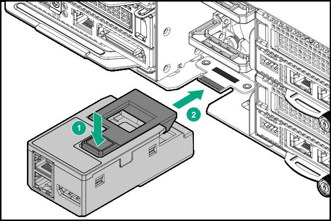
WARNING: To reduce the risk of electric shock or damage to the equipment:
         •   Never reach inside the chassis while the system is powered up.
         •   Perform service on system components only as instructed in the user documentation.

         CAUTION: Always be sure that equipment is properly grounded and that you follow proper
         grounding procedures before beginning any installation procedure. Improper grounding can result in
         ESD damage to electronic components. For more information, refer to "Electrostatic discharge on
         page 77."

         CAUTION: When performing non-hot-plug operations, you must power down the server and/or the
         system. However, it may be necessary to leave the server powered up when performing other
         operations, such as hot-plug installations or troubleshooting.

         CAUTION: Do not operate the server for long periods with the access panel open or removed.
         Operating the server in this manner results in improper airflow and improper cooling that can lead to
         thermal damage.

Space and airflow requirements
   Installation of the chassis is supported in 1200 mm Gen10 racks.
   To allow for servicing and adequate airflow, observe the following space and airflow requirements when
   deciding where to install a rack:

   •   Leave a minimum clearance of 63.5 cm (25 in) in front of the rack.
   •   Leave a minimum clearance of 76.2 cm (30 in) behind the rack.
   •   Leave a minimum clearance of 121.9 cm (48 in) from the back of the rack to the back of another rack
       or row of racks.

   Front and rear rack doors must be adequately ventilated to allow ambient room air to enter the cabinet,
   and the rear door must be adequately ventilated to allow the warm air to escape from the cabinet.

         CAUTION: To prevent improper cooling and damage to the equipment, do not block the ventilation
         openings.

   When vertical space in the rack is not filled by a chassis or rack component, the gaps between the
   components cause changes in airflow through the rack and across the components. Cover all gaps with
   blanking panels to maintain proper airflow.

         CAUTION: Always use blanking panels to fill empty vertical spaces in the rack. This arrangement
         ensures proper airflow. Using a rack without blanking panels results in improper cooling that can
         lead to thermal damage.

                                                                                  Planning the installation   9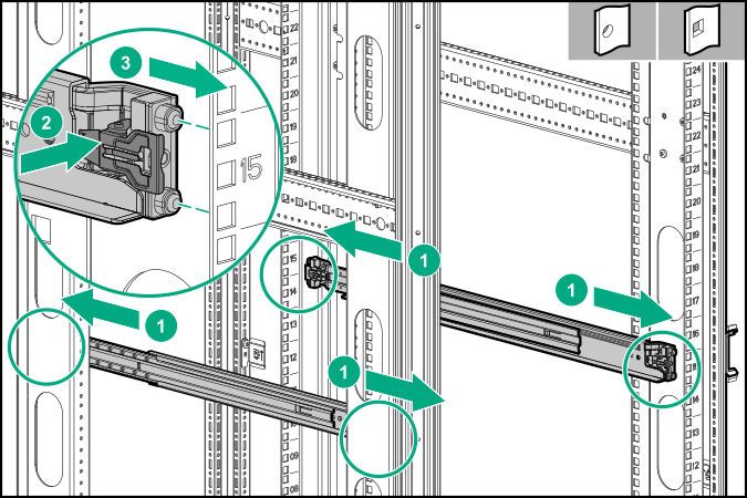
CAUTION: If a third-party rack is used, observe the following additional requirements to ensure
              adequate airflow and to prevent damage to the equipment:
              •   Front and rear doors—If the 42U rack includes closing front and rear doors, you must allow
                  5,350 sq cm (830 sq in) of holes evenly distributed from top to bottom to permit adequate airflow
                  (equivalent to the required 64 percent open area for ventilation).
              •   Side—The clearance between the installed rack component and the side panels of the rack must
                  be a minimum of 7 cm (2.75 in).

Temperature requirements
        To ensure continued safe and reliable equipment operation, install or position the rack in a well-ventilated,
        climate-controlled environment.
        The operating temperature inside the rack is always higher than the room temperature and is dependent
        on the configuration of equipment in the rack. Check the TMRA for each piece of equipment before
        installation.

              CAUTION: To reduce the risk of damage to the equipment when installing third-party options:
              •   Do not permit optional equipment to impede airflow around the chassis or to increase the internal
                  rack temperature beyond the maximum allowable limits.
              •   Do not exceed the manufacturer’s TMRA.

Grounding requirements
        •   The building installation must provide a means of connection to protective earth.
        •   The equipment must be connected to that means of connection.
        •   A service person must check whether the socket-outlet from which the equipment is to be powered
            provides a connection to the building protective earth. If the outlet does not provide a connection, the
            service person must arrange for the installation of a protective earthing conductor from the separate
            protective earthing terminal to the protective earth wire in the building.

Connecting a DC power cable to a DC power source
              WARNING: To reduce the risk of electric shock or energy hazards:
              •   This equipment must be installed by trained service personnel, as defined by the NEC and IEC
                  60950-1, Second Edition, the standard for Safety of Information Technology Equipment.
              •   Connect the equipment to a reliably grounded Secondary circuit source. A Secondary circuit has
                  no direct connection to a Primary circuit and derives its power from a transformer, converter, or
                  equivalent isolation device.
              •   The branch circuit overcurrent protection must be rated 20 A.

              WARNING: When installing a DC power supply, the ground wire must be connected before the
              positive or negative leads.

10   Planning the installation
WARNING: Remove power from the power supply before performing any installation steps or
maintenance on the power supply.
CAUTION: The server equipment connects the earthed conductor of the DC supply circuit to the
earthing conductor at the equipment. For more information, see the documentation that ships with
the power supply.
CAUTION: If the DC connection exists between the earthed conductor of the DC supply circuit and
the earthing conductor at the server equipment, the following conditions must be met:
• This equipment must be connected directly to the DC supply system earthing electrode
conductor or to a bonding jumper from an earthing terminal bar or bus to which the DC supply
system earthing electrode conductor is connected.
• This equipment should be located in the same immediate area (such as adjacent cabinets) as
any other equipment that has a connection between the earthed conductor of the same DC
supply circuit and the earthing conductor, and also the point of earthing of the DC system. The
DC system should be earthed elsewhere.
• The DC supply source is to be located within the same premises as the equipment.
• Switching or disconnecting devices should not be in the earthed circuit conductor between the
DC source and the point of connection of the earthing electrode conductor.
To connect a DC power cable to a DC power source:
1. Cut the DC power cord ends no shorter than 150 cm (59.06 in).
2. If the power source requires ring tongues, use a crimping tool to install the ring tongues on the power
cord wires.
IMPORTANT: The ring terminals must be UL approved and accommodate 12 gauge wires.
IMPORTANT: The minimum nominal thread diameter of a pillar or stud type terminal must be 3.5
mm (0.138 in); the diameter of a screw type terminal must be 4.0 mm (0.157 in).
3. Stack each same-colored pair of wires and then attach them to the same power source. The power
cord consists of three wires (black, red, and green).
For more information, see the documentation that ships with the power supply.
Planning the installation 11Identifying components and LEDs
System components
Item Description
1 RCM module (optional)
2 Power supply
3 HPE Apollo 2000 Gen10 Chassis
4 Fan
5 HPE ProLiant XL190r Gen10 Server
6 HPE ProLiant XL170r Gen10 Server
7 Server tray blank
Front panel components
HPE Apollo r2200 Gen10 Chassis
12 Identifying components and LEDsItem Description
1 Left bezel ear
2 Low-profile LFF hot-plug drives
3 Right bezel ear
4 Chassis serial label pull tab
HPE Apollo r2600 Gen10 Chassis
Item Description
1 Left bezel ear
2 SFF hot-plug drives
3 Right bezel ear
4 Chassis serial label pull tab
5 Non-removable bezel blank
HPE Apollo r2800 Gen10 Chassis with 16 NVMe
Identifying components and LEDs 13Item Description
1 Left bezel ear
2 NVMe drives
3 Right bezel ear
4 Chassis serial label pull tab
5 Non-removable bezel blanks
HPE Apollo r2800 Gen10 Chassis (24 SFF model with storage expander backplane)
Item Description
1 Left bezel ear
2 SFF hot-plug drives
3 Right bezel ear
4 Chassis serial label pull tab
5 Expander daughter module with power LED1
1 When the LEDs described in this table flash simultaneously, a power fault has occurred. For more information, see
Front panel LEDs on page 14.
Front panel LEDs
14 Identifying components and LEDsItem Description Status
1 Power On/Standby button and system power Solid green = System on
LED (Server 1)1
Flashing green = Performing power on
sequence Solid amber = System in standby
Off = No power present2
2 Power On/Standby button and system power Solid green = System on
LED (Server 2)1
Flashing green = Performing power on
sequence Solid amber = System in standby
Off = No power present2
3 Health LED (Server 2)1 Solid green = Normal
Flashing amber = System degraded
Flashing red = System critical3
4 Health LED (Server 1)1 Solid green = Normal
Flashing amber = System degraded
Flashing red = System critical3
5 Health LED (Server 3)1 Solid green = Normal
Flashing amber = System degraded
Flashing red = System critical3
6 Health LED (Server 4)1 Solid green = Normal
Flashing amber = System degraded
Flashing red = System critical3
7 Power On/Standby button and system power Solid green = System on
LED (Server 4)1
Flashing green = Performing power on
sequence Solid amber = System in standby
Off = No power present2
Table Continued
Identifying components and LEDs 15Item Description Status
8 UID button/LED1 Solid blue = Activated Flashing blue:
• 1 flash per second = Remote management or
firmware upgrade in progress
• 4 flashes per second = iLO manual soft
reboot sequence initiated
• 8 flashes per second = iLO manual hard
reboot sequence in progress
Off = Deactivated
9 Power On/Standby button and system power Solid green = System on
LED (Server 3)1
Flashing green = Performing power on
sequence Solid amber = System in standby
Off = No power present2
1 When the LEDs described in this table flash simultaneously, a power fault has occurred.
2 Facility power is not present, power cord is not attached, no power supplies are installed, power supply failure has
occurred, or the front I/O cable is disconnected.
3 If the health LED indicates a degraded or critical state, review the system IML or use iLO to review the system health
status.
24 SFF with expander daughter board LEDs
Item Description Status
1 Expander daughter board power good Solid green = Expander daughter board power is good
LED
Off = Issue with the expander daughter board power.
The expander daughter board power fault LED will be
on in this scenario.
2 Expander daughter board power fault Solid yellow = Expander daughter board power fault
LED has occurred
Off = Issue with the expander daughter board power.
The expander daughter board power fault LED will be
on in this scenario.
Power fault LEDs
The following table provides a list of power fault LEDs, and the subsystems that are affected. Not all
power faults are used by all servers.
16 Identifying components and LEDsSubsystem LED behavior
System board 1 flash
Processor 2 flashes
Memory 3 flashes
Riser board PCIe slots 4 flashes
FlexibleLOM 5 flashes
Removable HPE Flexible Smart Array 6 flashes
controller
System board PCIe slots 7 flashes
Power backplane or storage backplane 8 flashes
Power supply 9 flashes
Rear panel components
Four 1U servers
Item Description
1 Server 4
2 Server 3
3 Power supply 2
4 RCM module (optional)
5 Power supply 1
6 Server 2
7 Server 1
Two 2U servers
Identifying components and LEDs 17Item Description
1 Server 3
2 Power supply 2
3 RCM module (optional)
4 Power supply 1
5 Server 1
Power supply LED
Status Definition
Solid green The power supply is operating normally.
Off One or more of the following conditions exists
• Power is unavailable
• Power supply failure
• Power supply is in standby mode
• Power supply error
18 Identifying components and LEDsFan locations
NOTE: When installing an HPE 2200W Flex Slot Platinum Hot Plug Low Halogen Power Supply, make
sure that Fan 9 and Fan 10 are installed.
Drive bay numbering
IMPORTANT: Depending on the chassis configuration and the components installed in the servers,
it might be necessary to limit the number of drives installed in the chassis. For more information, see
Temperature requirements in the server user guide.
Apollo r2200 Gen10 Chassis (1U servers in AHCI mode)
Item Description
1 Server 1 drive bays
2 Server 2 drive bays
3 Server 3 drive bays
4 Server 4 drive bays
Identifying components and LEDs 19Apollo r2200 Gen10 Chassis (2U servers in AHCI mode)
Item Description
1 Server 1 drive bays
3 Server 3 drive bays
Apollo r2200 Gen10 Chassis (1U and 2U servers using embedded SATA S100i or a Smart Array
controller)
• One 1U server corresponds to a maximum of three low-profile LFF hot-plug drives.
◦ Server 1 corresponds to drive bays 1-1 through 1-3.
◦ Server 2 corresponds to drive bays 2-1 through 2-3.
◦ Server 3 corresponds to drive bays 3-1 through 3-3.
◦ Server 4 corresponds to drive bays 4-1 through 4-3.
• One 2U server corresponds to a maximum of six low-profile LFF hot-plug drives.
◦ Server 1 corresponds to drive bays 1-1 through 2-3.
◦ Server 3 corresponds to drive bays 3-1 through 4-3.
20 Identifying components and LEDsApollo r2600 Gen10 Chassis (1U servers in AHCI mode)
Item Description Supported drives
1 Server 1 drive bays Drive bays 1, 2, 3, and 4 support SFF SmartDrives
only. Drive bays 5 and 6 support both SFF SmartDrives
and NVMe drives.
2 Server 2 drive bays Drive bays 1 and 2 support both SFF SmartDrives and
NVMe drives. Drive bays 3, 4, 5, and 6 support SFF
SmartDrives only.
3 Server 3 drive bays Drive bays 1, 2, 3, and 4 support SFF SmartDrives
only. Drive bays 5 and 6 support both SFF SmartDrives
and NVMe drives.
4 Server 4 drive bays Drive bays 1 and 2 support both SFF SmartDrives and
NVMe drives. Drive bays 3, 4, 5, and 6 support SFF
SmartDrives only.
Apollo r2600 Gen10 Chassis (2U servers in AHCI mode)
Item Description Supported drives
1 Server 1 drive bays Drive bays 5, 6, 9, and 10 support both SFF
SmartDrives and NVMe drives. All other drive bays
support SFF SmartDrives only.
3 Server 3 drive bays Drive bays 5, 6, 9, and 10 support both SFF
SmartDrives and NVMe drives. All other drive bays
support SFF SmartDrives only.
Identifying components and LEDs 21Apollo r2600 Gen10 Chassis (1U and 2U servers using the embedded SATA S100i or a Smart Array
controller)
Drive bays 1-5, 1-6, 2-1, 2-2, 3-5, 3-6, 4-1, and 4-2 support both SFF SmartDrives and NVMe drives. All
other drives bays support SFF SmartDrives only.
• One 1U server corresponds to a maximum of six drives.
◦ Server 1 corresponds to drive bays 1-1 through 1-6.
◦ Server 2 corresponds to drive bays 2-1 through 2-6.
◦ Server 3 corresponds to drive bays 3-1 through 3-6.
◦ Server 4 corresponds to drive bays 4-1 through 4-6.
• One 2U server corresponds to a maximum of 10 drives. With a P408i-p or E208i-p Smart Array
controller installed, a 2U server can support up to eight SAS/SATA drives and two NVMe drives or six
SAS/SATA drives and four NVMe drives. With a P824i-p Smart Array controller installed, a 2U server
can support up to 12 SAS/SATA drives.
NOTE: With a P408i-p or E208i-p Smart Array controller installed, Server 1 and 3 does not support
SAS/SATA drives at drive bays 1-5, 1-6, 3-5, and 3-6. It supports NVMe drives only.
◦ Server 1 corresponds to drive bays 1-1 through 2-6.
◦ Server 3 corresponds to drive bays 3-1 through 4-6.
Apollo r2800 Gen10 Chassis with 16 NVMe
IMPORTANT: The HPE Apollo r2800 Gen10 Chassis with 16 NVMe does not support servers using
the embedded SATA HPE Dynamic Smart Array S100i Controller or any type-p plug-in Smart Array
Controller with internal ports and cables.
22 Identifying components and LEDs• One 1U server corresponds to a maximum of four NVMe drives.
◦ Server 1 corresponds to drive bays 1-1 through 1-4.
◦ Server 2 corresponds to drive bays 2-1 through 2-4.
◦ Server 3 corresponds to drive bays 3-1 through 3-4.
◦ Server 4 corresponds to drive bays 4-1 through 4-4.
• One 2U server corresponds to a maximum of eight NVMe drives.
◦ Server 1 corresponds to drive bays 1-1 through 2-4.
◦ Server 3 corresponds to drive bays 3-1 through 4-4.
Apollo r2800 Gen10 Chassis (24 SFF with storage expander backplane)
IMPORTANT: The HPE Apollo r2800 Gen10 Chassis with 24 SFF does not support servers using
the embedded SATA HPE Dynamic Smart Array S100i Controller and P824i-p Smart Array
Controller with internal ports and cables. It supports P408i-p and E208i-p Smart Array Controller.
The factory default configuration evenly distributes the 24 SFF drive bays in the HPE Apollo 2800
Chassis. For detailed information and examples on drive bay-mapping configuration changes in the HPE
Apollo r2800 Gen10 Chassis, see the iLO REST APIs to GitHub on the Hewlett Packard Enterprise
website.
NOTE: The layouts of the drives are internally mapped. The Redfish response or RESTful Interface Tool
still continues to display a fixed six drives irrespective of 1U or 2U node inserted.
The HPE Apollo r2800 Chassis, featuring the storage expander backplane, supports the flexibility to
assign drive bays to specific server nodes. This feature provides secure, remote configuration flexibility
Identifying components and LEDs 23through iLO Redfish interface. To deploy HDD bay-mapping configuration, iLO user account privilege
"Configure iLO Settings" is required.
Drive bay-mapping configuration changes may be made from any server node and take effect after all
server nodes in the HPE Apollo r2800 Chassis are turned off and the Chassis firmware is able to reset the
storage expander backplane. All nodes must remain powered off for at least 5 seconds after executing
the configuration changes. The server nodes may be remotely restarted through the iLO remote interface,
or may be locally restarted by pressing the power button for each node.
This feature requires the following minimum firmware versions:
• Apollo 2000 System Chassis firmware version 1.2.10 or later
• Storage Expander firmware version 1.0 or later
• iLO firmware version 1.20 or later
• Six drive bays are allocated to each 1U node.
◦ Server 1 corresponds to drive bays 1 through 6.
◦ Server 2 corresponds to drive bays 7 through 12.
◦ Server 3 corresponds to drive bays 13 through 18.
◦ Server 4 corresponds to drive bays 19 through 24.
• 12 drive bays are allocated to each 2U node.
◦ Server 1 corresponds to drive bays 1 through 12.
◦ Server 3 corresponds to drive bays 13 through 24.
Drive bay mapping
The Apollo 2000 System with the r2800 Chassis (including the Storage Expander Backplane) supports 24
small form factor (SFF) drives. The SFF drive bays can be assigned to specific server nodes.
The default configuration divides the 24 SFF drive bays by the number of server host ports in the Apollo
2000 Chassis. In a configuration with four 1U servers, the default drive bay configuration is six drive bays
allocated to each of the four server slots. In a configuration with two 2U servers, the default drive bay
configuration is 12 drive bays allocated to each of the two server slots.
Backplane details
SEP Firmware Version
The storage enclosure processor backplane firmware version.
SEP WWID
The storage enclosure processor world wide identifier.
System Configuration Type
The configuration type. iLO currently supports Type 1: One storage enclosure processor (with multiple
bays) shared across multiple nodes.
Total Bay
The total number of storage bays attached to storage enclosure processors.
24 Identifying components and LEDsStart Bay Number
The starting number of the range of storage bays.
End Bay Number
The ending number of the range of storage bays.
Host port topology details
The Host Port Topology section displays the node number and SAS controller associated with each
server host port.
Current drive bay mapping details
The Current Drive Bay Mapping section lists all the drive bays and whether they are unassigned or
mapped to a host port.
Configuring drive bay mapping
Prerequisites
• Configure iLO Settings privilege
• iLO firmware 1.20 or later
• Storage enclosure processor firmware 1.00 or later
• Chassis firmware 1.2.10 or later
Procedure
1. Click Chassis Information in the navigation tree, and then click the Drive Bay Mapping tab.
Each drive bay is listed in a table with the host port numbers you can select.
2. To assign a drive bay to a host port number, click in a Host Port Number column.
Identifying components and LEDs 25CAUTION: Changing the drive bay mapping configuration might cause data loss or data
corruption. For example, consider a configuration with drive bays one through six assigned to
node 1, with the drives configured as a RAID0 volume. Data corruption might occur if you
change the drive bay mapping so that the configured drives are no longer available.
Each drive bay is listed in a table with the host port numbers you can select.
3. Optional: To clear a selected value, click in the Unassigned column.
To unassign all values, click Unassign All.
4. Click Apply.
iLO notifies you that data loss or corruption might occur when you change the drive bay mapping
configuration.
5. Click Yes, apply to confirm the change.
6. Shut down all the server nodes in the Apollo 2000 Chassis.
7. Wait for at least five seconds for the Chassis firmware to reset the Storage Expander backplane.
8. Restart the server nodes.
Setting the drive bay mapping configuration to the default configuration
Prerequisites
• Configure iLO Settings privilege
• iLO firmware 1.20 or later
• Storage enclosure processor firmware 1.00 or later
• Chassis firmware 1.2.10 or later
Procedure
1. Click Chassis Information in the navigation tree, and then click the Drive Bay Mapping tab.
Each drive bay is listed in a table with the host port numbers you can select.
2. Click Reset to Default
CAUTION: Changing the drive bay mapping configuration might cause data loss or data
corruption. For example, consider a configuration with drive bays two through seven assigned to
node 1, with the drives configured as a RAID0 volume. Data corruption might occur if you
change the drive bay mapping so that the configured drives are no longer available.
3. Click Apply.
4. iLO notifies you that data loss or data corruption might occur when you change the drive bay mapping
configuration.
5. Click Yes, apply.
6. Shut down all the server nodes in the Apollo 2000 Chassis.
26 Identifying components and LEDs7. Wait for at least five seconds for the Chassis firmware to reset the Storage Expander backplane.
8. Restart the server nodes.
Hot-plug drive LED definitions
SmartDrive hot-plug drive LED definitions
Item Description Status
1 Locate • Solid blue = The drive is being identified by a host
application.
• Flashing blue = The drive carrier firmware is being
updated or requires an update.
2 Activity ring LED • Rotating green = Drive activity.
• Off = No drive activity.
Table Continued
Identifying components and LEDs 27Item Description Status
3 Do not remove LED • Solid white = Do not remove the drive. Removing
the drive causes one or more of the logical drives to
fail.
• Off = Removing the drive does not cause a logical
drive to fail.
4 Drive status LED • Solid green = The drive is a member of one or more
logical drives.
• Flashing green = The drive is rebuilding or
performing a RAID migration, strip size migration,
capacity expansion, or logical drive extension, or is
erasing.
• Flashing amber/green = The drive is a member of
one or more logical drives and predicts the drive will
fail.
• Flashing amber = The drive is not configured and
predicts the drive will fail.
• Solid amber = The drive has failed.
• Off = The drive is not configured by a RAID
controller.
Low-profile LFF hot-plug drive LED definitions
Item Definition
1 Fault/UID (amber/blue)
2 Online/Activity (green)
LED Activity
28 Identifying components and LEDsOnline/Activity LED (green) Fault/UID LED (amber/blue) Definition
On, off, or flashing Alternating amber and blue One or more of the following
conditions exist:
• The drive has failed.
• A predictive failure alert has
been received for this drive.
• The drive has been selected
by a management application.
On, off, or flashing Solid blue One or both of the following
conditions exist:
• The drive is operating
normally.
• The drive has been selected
by a management application.
On Flashing amber A predictive failure alert has been
received for this drive. Replace
the drive as soon as possible.
On Off The drive is online but is not
currently active.
1 flash per second Flashing amber Do not remove the drive.
Removing the drive might
terminate the current operation
and cause data loss.
The drive is part of an array that
is undergoing capacity expansion
or stripe migration, but a
predictive failure alert has been
received for this drive. To
minimize the risk of data loss, do
not remove the drive until the
expansion or migration is
complete.
1 flash per second Off Do not remove the drive.
Removing the drive might
terminate the current operation
and cause data loss.
The drive is rebuilding, erasing,
or is part of an array that is
undergoing capacity expansion or
stripe migration.
4 flashes per second Flashing amber The drive is active but a
predictive failure alert has been
received for this drive. Replace
the drive as soon as possible.
Table Continued
Identifying components and LEDs 29Online/Activity LED (green) Fault/UID LED (amber/blue) Definition
4 flashes per second Off The drive is active and is
operating normally.
Off Solid amber A critical fault condition has been
identified for this drive and the
controller has placed it offline.
Replace the drive as soon as
possible.
Off Flashing amber A predictive failure alert has been
received for this drive. Replace
the drive as soon as possible.
Off Off The drive is offline, a spare, or
not configured as part of an array.
NVMe SSD LED definitions
The NVMe SSD is a PCIe bus device. A device attached to a PCIe bus cannot be removed without
allowing the device and bus to complete and cease the signal/traffic flow.
CAUTION: Do not remove an NVMe SSD from the drive bay while the Do not remove LED is
flashing. The Do not remove LED flashes to indicate that the device is still in use. Removing the
NVMe SSD before the device has completed and ceased signal/traffic flow can cause loss of data.
Item LED Status Definition
1 Locate Solid blue The drive is being identified by a host application.
Flashing blue The drive carrier firmware is being updated or requires an update.
2 Activity Rotating green Drive activity
ring
Off No drive activity
3 Drive Solid green The drive is a member of one or more logical drives.
status
Table Continued
30 Identifying components and LEDsItem LED Status Definition
Flashing green The drive is doing one of the following:
• Rebuilding
• Performing a RAID migration
• Performing a stripe size migration
• Performing a capacity expansion
• Performing a logical drive extension
• Erasing
Flashing amber/ The drive is a member of one or more logical drives and predicts the
green drive will fail.
Flashing amber The drive is not configured and predicts the drive will fail.
Solid amber The drive has failed.
Off The drive is not configured by a RAID controller.
4 Do not Solid white Do not remove the drive. The drive must be ejected from the PCIe bus
remove prior to removal.
Flashing white The drive ejection request is pending.
Off The drive has been ejected.
5 Power Solid green Do not remove the drive. The drive must be ejected from the PCIe bus
prior to removal.
Flashing green The drive ejection request is pending.
Off The drive has been ejected.
RCM module
RCM module components
Identifying components and LEDs 31Item Description
1 iLO connector
2 HPE APM 2.0 connector
3 iLO connector
RCM module LEDs
Item Description Status
1 iLO activity LED Green or flashing green = Network activity
Off = No network activity
2 iLO link LED Green = Linked to network
Off = No network connection
3 iLO link LED iLO link LED Green = Linked to network
Off = No network connection
4 iLO activity LED Green or flashing green = Network activity
Off = No network activity
32 Identifying components and LEDsInstalling the chassis
Installation overview
To set up and install the chassis:
1. Unpack the system.
2. Prepare the chassis for installation.
3. Install the rack rails and chassis into the rack.
4. Install hardware options into the servers.
5. Install the system components.
6. Cable the chassis.
Unpacking the system
Unpack the following hardware and prepare for installation:
• HPE Apollo 2000 Gen10 Chassis
• Rack rail kit
• System components and cabling
The following documents also ship with the HPE Apollo 2000 Gen10 Chassis:
• Start Here for Important Setup Information
• Safety, Compliance, and Warranty Information
Preparing the chassis for installation
If installing the Smart Storage Battery and redundant fan options, install these options before installing the
chassis into the rack.
Prerequisites
Before installing the chassis into the rack, Hewlett Packard Enterprise recommends removing the servers
and drives. The fully populated chassis is heavy and removing the servers facilitates easy movement and
installation of the chassis.
Procedure
1. If installed, remove the bezel.
Installing the chassis 33IMPORTANT: Label the drives before removing them. The drives must be returned to their
original locations.
2. Remove the hot-plug drive.
• SFF SmartDrive
• Low-profile LFF hot-plug drive
• NVMe hot-plug drive
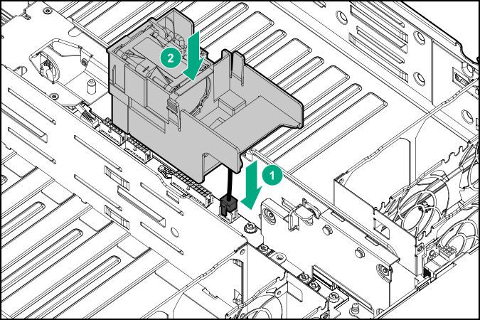
34 Installing the chassis3. Remove the server from the chassis:
a. Loosen the thumbscrew.
b. Pull back the handle.
CAUTION: To avoid damage to the server, always support the bottom of the server when
removing it from the chassis.
c. Remove the server.
• 1U server
• 2U server
Installing the chassis 35HPE Smart Storage Battery
The HPE Smart Storage Battery supports the following devices:
• HPE Smart Storage SR controllers
• HPE Smart Storage MR controllers
A single 96W battery can support up to 24 devices.
After the battery is installed, it might take up to two hours to charge. Controller features requiring backup
power are not re-enabled until the battery is capable of supporting the backup power.
This server supports the 96W HPE Smart Storage Battery with the 145mm cable.
Installing the HPE Smart Storage Battery
NOTE: System ROM and firmware messages might display "energy pack" in place of "Smart Storage
Battery." Energy pack refers to both, HPE Smart Storage Battery and the HPE Smart Storage Hybrid
Capacitor.
Prerequisites
Before you perform this procedure:
• Make sure that a Smart Array P-class Gen10 controller is installed.
For more information, see the server user guide on the Hewlett Packard Enterprise website (http://
www.hpe.com/info/Apollo2000-Gen10-docs).
• If an HPE 2200W Flex Slot Platinum Hot Plug Low Halogen Power Supply is installed, make sure that
fan 9 and fan 10 are installed.
• T-10 Torx screwdriver
36 Installing the chassisProcedure
1. To install the smart storage battery for standard power supply and HPE 2200W Flex Slot Platinum Hot
Plug Low Halogen Power Supply, prepare the chassis for installation.
2. Remove the access panel.
NOTE: The Smart Storage Battery is supported with P408i-p, P408e-p, and P824i-p controllers only.
Due to thermal concerns on some configurations, Hewlett Packard Enterprise recommends that you
remove the Smart Storage Battery if these cards are not installed in the chassis.
3. Do one of the following:
a. For standard power supply, do the following:
I. Remove the screw, and then the PDB cover.
Installing the chassis 37II. Remove the battery holder.
b. For HPE 2200W Flex Slot Platinum Hot Plug Low Halogen Power Supply, do the following:
I. Install the fan into the fan cage, and then connect the fan cable.
38 Installing the chassisII. Install the fan cage in the chassis and connect the cable to the system board.
4. Install the smart storage battery into the holder.
• Smart storage battery with the standard power supply
Installing the chassis 39• Smart storage battery with the HPE 2200 W Flex Slot Platinum Hot Plug Low Halogen Power
Supply
5. Install the energy pack assembly into the chassis.
• Chassis with the standard power supply
40 Installing the chassis• Chassis with the HPE 2200W Flex Slot Platinum Hot Plug Low Halogen Power Supply
6. Install the access panel.
Installing the chassis 41The installation is complete.
Installing the redundant fan option
Procedure
1. To install the redundant fan option, do the following:
NOTE: Depending on the power supply installed, the design of the SmartStorage battery and the fan
cage and module may be slightly different.
a. Disconnect the fan module cables for fans 1, 2, 3, and 4. Be careful not to remove any existing
adhesive tape.
b. Install the redundant fans.
42 Installing the chassisc. Route the fan 1 and fan 5 cables through the grooves on the top of fan 5. Then secure the cables
on top of fan 5 with two strips of adhesive tape.
d. Repeat the previous step for fans 6, 7, and 8.
e. Connect all fan module cables.
2. Install the access panel.
The installation is complete.
Installing the chassis 43Installing the chassis into the rack
WARNING: The chassis is very heavy. To reduce the risk of personal injury or damage to the
equipment:
• Observe local occupational health and safety requirements and guidelines for manual material
handling.
• Remove all servers from the chassis before installing or moving the chassis.
• Use caution and get help to lift and stabilize the chassis during installation or removal, especially
when the chassis is not fastened to the rack.
WARNING: To avoid risk of personal injury or damage to the equipment, do not stack anything on
top of rail-mounted equipment or use it as a work surface when extended from the rack.
WARNING: To reduce the risk of personal injury or damage to the equipment, be sure that:
• The rack is bolted to the floor using the concrete anchor kit.
• The leveling feet extend to the floor.
• The full weight of the rack rests on the leveling feet.
• The racks are coupled together in multiple rack installations.
• Only one component is extended at a time. If more than one component is extended, a rack
might become unstable.
WARNING: To reduce the risk of personal injury or equipment damage, be sure that the rack is
adequately stabilized before installing the chassis.
CAUTION: Always plan the rack installation so that the heaviest item is on the bottom of the rack.
Install the heaviest item first, and continue to populate the rack from the bottom to the top.
CAUTION: Be sure to keep the product parallel to the floor when installing the chassis. Tilting the
product up or down could result in damage to the slides.
CAUTION: Hewlett Packard Enterprise has not tested or validated this chassis with any third-party
racks. Before installing the chassis in a third-party rack, be sure to properly scope the limitations of
the rack. Before proceeding with the installation, consider the following:
• You must fully understand the static and dynamic load carrying capacity of the rack and be sure
that it can accommodate the weight of the chassis.
• Be sure sufficient clearance exists for cabling, installation and removal of the chassis, and
actuation of the rack doors.
IMPORTANT: When installing each chassis into the rack, be sure that the HPE Apollo Platform
Manager is at the top of the chassis to ensure proper orientation in the rack.
44 Installing the chassisInstalling the 2U rack rail kit
WARNING: To reduce the risk of personal injury or damage to the equipment, be sure that:
• The leveling jacks are extended to the floor.
• The full weight of the rack rests on the leveling jacks.
• The stabilizing feet are attached to the rack if it is a single-rack installation.
• The racks are coupled together in multiple-rack installations.
• Only one component is extended at a time. A rack may become unstable if more than one
component is extended for any reason.
WARNING: If you are going to use a lift, be sure to use a lift that can handle the load of the
component.
Procedure
1. Insert the 2U rack rails into the columns.
2. Secure the 2U rails with two panhead screws at the rear of the rack.
• Square-hole rack
Installing the chassis 45You can also read