Using the Nintendo Wii to Assess Motility in the Elderly - Becca Groveman
←
→
Page content transcription
If your browser does not render page correctly, please read the page content below
Using the Nintendo Wii to Assess Motility in the
                   Elderly

                 Becca Groveman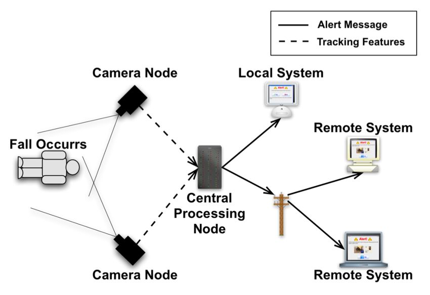
Contents

1 Introduction                                                                                                                 4
  1.1 Problem and Importance . . . . . . . . . . . . . . . . . . . . . . . . .                                                 4
  1.2 Possible Applications . . . . . . . . . . . . . . . . . . . . . . . . . . .                                              5

2 Background                                                                                                                   7
  2.1 Technology to Support Aging in Place . . . . .                          .   .   .   .   .   .   .   .   .   .   .   .    7
  2.2 3D Tracking, Learning, and Gesture Recognition                          .   .   .   .   .   .   .   .   .   .   .   .   10
  2.3 The Nintendo Wii . . . . . . . . . . . . . . . . .                      .   .   .   .   .   .   .   .   .   .   .   .   12
      2.3.1 Utilizing the Wii . . . . . . . . . . . . .                       .   .   .   .   .   .   .   .   .   .   .   .   12
      2.3.2 Bluetooth . . . . . . . . . . . . . . . . .                       .   .   .   .   .   .   .   .   .   .   .   .   14
  2.4 My Project . . . . . . . . . . . . . . . . . . . .                      .   .   .   .   .   .   .   .   .   .   .   .   15

3 Methods and Methodology                                                                                                     16
  3.1 User Interaction . . . . . . . . . .    .   .   .   .   .   .   .   .   .   .   .   .   .   .   .   .   .   .   .   .   16
      3.1.1 Technicians . . . . . . . .       .   .   .   .   .   .   .   .   .   .   .   .   .   .   .   .   .   .   .   .   17
      3.1.2 Elderly Users . . . . . . .       .   .   .   .   .   .   .   .   .   .   .   .   .   .   .   .   .   .   .   .   18
      3.1.3 Caregivers . . . . . . . . .      .   .   .   .   .   .   .   .   .   .   .   .   .   .   .   .   .   .   .   .   19
  3.2 Data Collection . . . . . . . . . .     .   .   .   .   .   .   .   .   .   .   .   .   .   .   .   .   .   .   .   .   19
      3.2.1 Use of Bluetooth . . . . .        .   .   .   .   .   .   .   .   .   .   .   .   .   .   .   .   .   .   .   .   20
      3.2.2 Connecting the Wiimotes           .   .   .   .   .   .   .   .   .   .   .   .   .   .   .   .   .   .   .   .   20
  3.3 Camera Calibration . . . . . . . .      .   .   .   .   .   .   .   .   .   .   .   .   .   .   .   .   .   .   .   .   22
      3.3.1 Calibration Square Step .         .   .   .   .   .   .   .   .   .   .   .   .   .   .   .   .   .   .   .   .   23
      3.3.2 Single Camera Calibration         .   .   .   .   .   .   .   .   .   .   .   .   .   .   .   .   .   .   .   .   24
      3.3.3 Stereo Calibration . . . .        .   .   .   .   .   .   .   .   .   .   .   .   .   .   .   .   .   .   .   .   25
  3.4 Data Gathering Step . . . . . . .       .   .   .   .   .   .   .   .   .   .   .   .   .   .   .   .   .   .   .   .   26
      3.4.1 Stereo Triangulation . . .        .   .   .   .   .   .   .   .   .   .   .   .   .   .   .   .   .   .   .   .   26
      3.4.2 Gesture Recognition . . .         .   .   .   .   .   .   .   .   .   .   .   .   .   .   .   .   .   .   .   .   27
  3.5 Data Analysis . . . . . . . . . . .     .   .   .   .   .   .   .   .   .   .   .   .   .   .   .   .   .   .   .   .   28

                                          1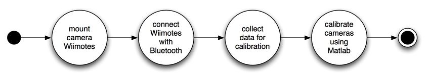
3.5.1 IR Data Analysis . . .     .   .   .   .   .   .   .   .   .   .   .   .   .   .   .   .   .   .   .   .   .   .   29
         3.5.2 Gesture Data Analysis      .   .   .   .   .   .   .   .   .   .   .   .   .   .   .   .   .   .   .   .   .   .   29
         3.5.3 Data Visualization . .     .   .   .   .   .   .   .   .   .   .   .   .   .   .   .   .   .   .   .   .   .   .   30
   3.6   Experimental Setup . . . . . .   .   .   .   .   .   .   .   .   .   .   .   .   .   .   .   .   .   .   .   .   .   .   34

4 Experiments and Results                                                          35
  4.1 Accuracy of System . . . . . . . . . . . . . . . . . . . . . . . . . . . . 35
  4.2 Usability Issues . . . . . . . . . . . . . . . . . . . . . . . . . . . . . . 36
  4.3 Fit of the Wii . . . . . . . . . . . . . . . . . . . . . . . . . . . . . . . 37

5 Conclusion and Future Research                                                  38
  5.1 Conclusions . . . . . . . . . . . . . . . . . . . . . . . . . . . . . . . . 38
  5.2 Future Research . . . . . . . . . . . . . . . . . . . . . . . . . . . . . . 39

A Sample Scripts                                                                42
  A.1 Single Camera Calibration Script . . . . . . . . . . . . . . . . . . . . 42
  A.2 Triangulation Script for Data Visualization . . . . . . . . . . . . . . . 44

                                              2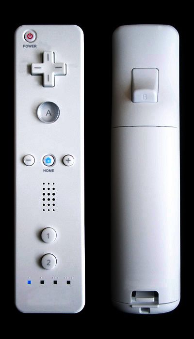
List of Figures

 2.1    Image of the uBot-5 [6] . . . . . . . . . . . . . . . . . . . . . . . . . .    8
 2.2    Analysis of video data for fall detection and object finding [31] . . . .     10
 2.3    Use of video data to track body contours and exercise effectiveness [7]       11
 2.4    The Nintendo Wiimote [4] . . . . . . . . . . . . . . . . . . . . . . . .      12
 2.5    Axes and Rotation of the Nintendo Wiimote [3] . . . . . . . . . . . .         13

 3.1    Elder interaction with Wiimotes for Project . . . . . . . . . . . . . .       17
 3.2    State diagram representing user interaction . . . . . . . . . . . . . .       18
 3.3    State diagram representing technician’s role . . . . . . . . . . . . . .      18
 3.4    State diagram representing elderly user’s role . . . . . . . . . . . . .      19
 3.5    Screenshot of Wiimote Interface . . . . . . . . . . . . . . . . . . . . .     21
 3.6    Diagram of Wiimotes and IR Interface . . . . . . . . . . . . . . . . .        22
 3.7    Screenshot of Calibration Square (from “Hacking Wiis for 3D track-
        ing” YouTube video [14]) . . . . . . . . . . . . . . . . . . . . . . . . .    23
 3.8    Example of raw IR data . . . . . . . . . . . . . . . . . . . . . . . . .      24
 3.9    Diagram of camera calibration for one Wiimote . . . . . . . . . . . .         25
 3.10   Diagram of camera calibration for two Wiimotes . . . . . . . . . . . .        26
 3.11   Diagram of Wiigee and gesture recognition . . . . . . . . . . . . . . .       28
 3.12   Gesture visualization program . . . . . . . . . . . . . . . . . . . . . .     31
 3.13   Head-on view of IR LED square pattern during single bowling motion            32
 3.14   3D view of IR LED square pattern during single bowling motion . . .           33

                                          3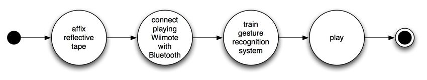
Chapter 1

Introduction

The first generation of the “baby boomer” cohort will turn 65 in 2011 [10]. By 2050,
there will be three times as many elders over the age of 85 as there are today [30].
As a result, in-home elderly care is becoming an important issue. Currently, much of
the technology available to assist the elderly takes the form of technology that can
be worn on the body, such as necklaces or bracelets with emergency buttons or GPS
to alert caregivers of a problem. However, technology in this form is obtrusive, in
the sense that the elder is constantly aware of its presence, and that the elder must
remember to wear it in order for it to be effective.
    An alternative to this technology is in the socially assistive robotics currently
being developed. Socially assistive robotics is a phrase referring to technological sys-
tems that offer assistance in the form of social, rather than physical interaction [30].
While this technology sometimes includes the presence of an embodied robot [22] [23],
more often it takes the form of a distributed sensor system.
    A distributed sensor system is a system that utilizes sensor technology such as
video capture, fall detection, and other sensors such as bed or stove sensors. These
sensors are installed in a given living space, providing a level of care to the person
living in the space, while still allowing the user to feel independent.

1.1      Problem and Importance
The rising costs of health care and the increasing number of elders in society [10] call
for an alternative to institutional support. This alternative should be inexpensive
and unobtrusive, while still providing sufficient coverage. Elders prefer to remain
independent for as long as possible, creating demand for technology to assist in
aging in place [27].

                                           4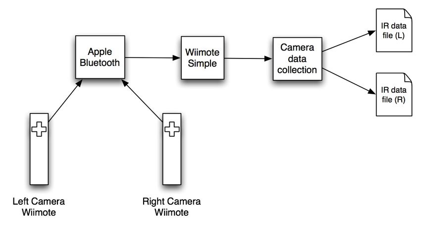
There are many high-end systems that assess motility. Motility analysis, or anal-
ysis of how well a person is able to move, is an important topic in eldercare. Motility
analysis gives an assessment of a person’s physical well-being; if a person is doing
well, a physical therapist or doctor is able to say with certainty that the person is
physically able to live alone, which helps elders to stay independent for longer. How-
ever, such systems are expensive and require specialized equipment. My project asks
the question of whether it is possible to utilize an inexpensive and unobtrusive sys-
tem to capture a person’s movements sufficiently to assess motility. To that end, my
project explores the viability of using the Nintendo Wii as an inexpensive alternative
to the high-end systems available.
    The Nintendo Wiimote is a sophisticated piece of equipment that is inexpensive
(at $40) compared to other sensor systems available. It has an infrared camera and
three accelerometers, allowing it to detect acceleration along the X, Y, and Z axes.
In addition to being an inexpensive alternative to high-end systems, the Wii can
also be used as an unobtrusive tool to monitor the elderly. The Wii was designed to
appeal to a broad audience [32], and elders are among its users [33].
    Since many elders are playing the Wii, and the Wiimotes used can generate such
advanced and useful data, utilizing the Wii to monitor motility in the elderly becomes
an option worth exploring.
    It is important to note that while one Wiimote is inexpensive, my system uses
three Wiimotes, a Wii, and a computer, for a minimum cost of $700, more if using
a more expensive computer. Nevertheless, $700 is considerably less than the cost
of the larger research systems, especially because this setup can be used at home
or at a senior center, and allow the user to play the Wii. Other systems require an
elderly person to go somewhere to perform activities for the sole purpose of assessing
physical well-being.

1.2     Possible Applications
The high-end systems available can collect data with a greater accuracy than the
Wiimote can, and can collect more data; while the Wiimote can track up to four
IR points simulataneously, a research system can track many more, and with more
precision. Further, these systems can visualize the data with greater sophistication.
One example of such a system is the one in place at the Kinesiology Lab at the
University of Massachusetts Amherst [11]. While the Wii cannot compete with
such an advanced system, it is inexpensive, intuitive, and accepted by the elderly
population. The Wii may be an acceptable substitute to allow for more frequent
motility analysis. The goal of my project is to determine whether it can be used to

                                          5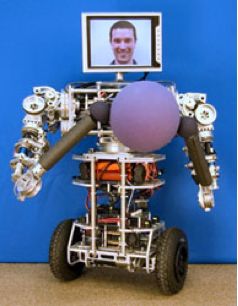
gather data with sufficient accuracy to be useful.
   If successful, this project could be a welcome addition to the more advanced
systems currently in use. Elders could play the Wii while the system collects data,
and physical therapists or doctors could examine the data visually.

                                        6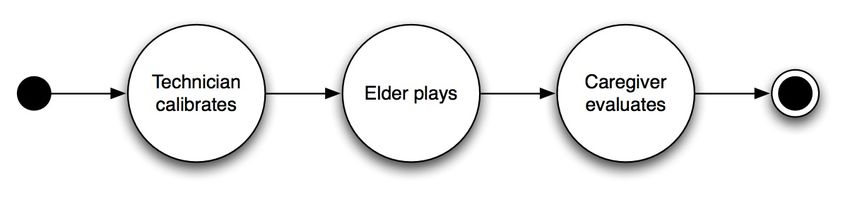
Chapter 2

Background

My project is based around two seemingly different areas: the Nintendo Wii and
eldercare. Technology to assist the elderly often takes the form of embodied robotics
systems, utilization of video data, and distributed sensor systems. Some of this
technology is discussed in Section 2.1. Machine learning and gesture recognition
are discussed in Section 2.2. The Nintendo Wii is discussed in Section 2.3, and my
project is laid out in Section 2.4.

2.1     Technology to Support Aging in Place
The “baby boomer” generation is on the cusp of reaching retirement age, an issue
which is significant because it indicates that the number of elders in the population
will increase dramatically. Due to health care costs and a shortage of nurses and
doctors, institutional support for such a large number of elders will not be possi-
ble [10]. Coupled with the fact that elders prefer to stay in their own homes and
remain independent as long as possible [27], the need arises for technologies that are
both affordable and unobtrusive, and that help the elderly to age in place for as long
as possible.
    One challenge in designing assistive robotics systems for the elderly is that these
systems must be user-friendly enough to interact with people who may be techno-
phobic or uncomfortable with the technology being used. Further, they must be
capable of understanding natural communication such as gestures or speech, and of
assisting the user with basic daily activities [30].
    Much of the work that has been done in socially assistive computing for the
elderly involves distributed sensor systems, both in the form of robotics with an
embodied physical presence, and in the form of smart cameras and sensors. It is

                                          7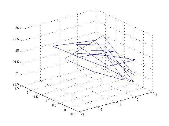
believed that the physical embodiment of a robot makes a key difference in the
system’s effectiveness [22]. In this section, I describe a few of the distributed sensor
systems that have been designed to help elders to age in place.
    The ASSIST framework [10] is a collaboration between the University of Mas-
sachusetts, Amherst, and Smith College. It seeks to bring together computer scien-
tists, social scientists and gerontologists to examine the way in which technology is
adopted by the elderly. It also looks at the impact of technology on the well being
of the elderly and on health care delivery.
    Elderly focus group participants were enthused about the usage of video tech-
nology, which has prompted the ASSIST group to develop the uBot, a mobile robot
able to follow the user around. The uBot [6] has a touch screen that allows it to
interact with the user and act as the embodiment of the distributed system. It is
able to communicate through gesture, motion, and verbal commands, and can act
as a substitute for health care and service providers who cannot be present [10]. An
image of the uBot can be seen in Figure 2.1.

                         Figure 2.1: Image of the uBot-5 [6]

                                           8
In addition to the uBot, the ASSIST system is built on another key technology:
the distributed sensor array. Activity modeling occurs through the use of this array.
Activities are defined as observational temporal patterns consisting of auditory, vi-
sual, and haptic feedback that can be extracted from the environment and analyzed.
In the ASSIST framework, Hidden Markov Models (HMMs) are used in order to
determine the underlying process or pattern that results in these patterns of activ-
ity. (Hidden Markov models are discussed in more detail in Section 2.2.) Through
HMMs, it can be determined whether an activity sequence is a fall or not, based on
the likelihood of a given sequence.
Further, through the help of a remote doctor, the uBot can determine whether or
not a fall is stroke-related. If a distributed sensor network with embodied component
is present, the system would be able to rule out false alarms and perform remote
diagnoses and triage [10].
The idea of the distributed sensor network is further discussed by Williams, Xie,
Ou, et al [31]. Contrary to many aging-in-place aids currently in use, which involve
devices that are worn or attached to objects, this group relies heavily on the analysis
of video data. They have developed a fall detector and an object finder using a central
processing node and multiple camera nodes in a given living space. A visualization of
this setup can be seen in Figure 2.2. In addition, in most major living spaces the user
will have a display, speakers, and an input device, which will allow communication
between the user and the central processing node. If a fall is detected, the central
processing node initiates the alert procedure.
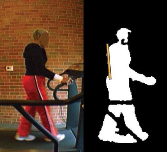
Video data is also used in a collaborative project between the Sinclair School of
Nursing and the Department of Electrical and Computer Engineering at the Uni-
versity of Missouri [7]. They designed a system to increase effectiveness of exercise
routines for elders. The system uses video data and tracks the contours of human
bodies and extracts the silhouettes of the subjects, as seen in Figure 2.3. The study
compared posture and smoothness of gait in the two case study participants.
Distributed sensor systems for the elderly are also employed at TigerPlace, a
retirement community in Missouri designed to help the elderly to age in place [27].
They use a sensor network with an event-driven architecture, and consists of bed,
motion and stove sensors with a video sensor system. The framework is used to
detect falls, restless sleep, change in gait or activity levels, and in users’ routine. The
system includes a reasoning component involved with pattern recognition to allow it
to detect these changes.
9Figure 2.2: Analysis of video data for fall detection and object finding [31]
2.2 3D Tracking, Learning, and Gesture Recogni-
tion
Pattern recognition poses a challenge in computer science and machine learning,
because patterns can be sophisticated and ambiguous, which are difficult for a com-
puter to parse. Two areas that are particularly challenging are speech and gesture
recognition. All words are made of phonemes, and all gestures from motions, but
each motion or phoneme might be part of many gestures or words. In addition, there
is no single precise way to pronounce every word or perform each gesture, creating
a huge amount of variability. While computers are able to observe the input, the
challenge is in synthesizing the data to be able to understand its meaning. Hidden
Markov models provide a way to analyze the data to find these patterns.
In each case, the input is observable, but the output, the meanings, are unknown.
For this reason, these processes are doubly stochastic [20]: processes whose state
cannot be directly observed.
Hidden Markov Models, also known as Hidden Markov processes, are an example
10Figure 2.3: Use of video data to track body contours and exercise effectiveness [7]
of dynamic Bayesian networks [12] in which some parameters are known and some
are hidden. The goal is to deduce the hidden parameters, given the parameters that
are observable [26].
A Bayesian network is a graphical representation of the probabilistic relationships
in a set of variables. Bayesian networks are significant in that they help one to
learn about causal relationships, and allow for the examination of incomplete data
sets [17]. Hidden Markov Models are particularly useful in the field of speech [26]
and gesture [20] [28] recognition.
Bennewitz, Burgard, and Thrun [8] utilize Hidden Markov Models and an
expectation-maximization (EM) algorithm to enable a mobile robot to follow people
and avoid obstacles. This task is accomplished through a machine learning (ML)
algorithm that learns the typical trajectories and patterns that comprise human mo-
tion. This ML might allow a mobile robot to make decisions and detours that would
minimize the chance of a collision.
Machine learning and pattern recognition are also used in the design of the Inde-
pendent Lifestyle Assistant (I.L.S.A.) developed at Honeywell Laboratories. Through
11machine learning techniques, I.L.S.A. will be able to accurately model human be-
havior, which will allow it to recognize human actions and respond accordingly [13].
An application of Hidden Markov Models for gesture recognition can be seen in
work by Lee and Xu [20]. Lee and Xu have designed a system in which a user signs
letters of the American Sign Language alphabet while wearing a ‘cyberglove.’ The
cyberglove allows the computer to observe the gestures, which can be interpreted
and classified interactively as specific letters through the use of HMMs.
2.3 The Nintendo Wii
2.3.1 Utilizing the Wii
While the Nintendo Wii is primarily a gaming console, its advanced technology and
relative affordability have attracted many alternate uses. The Wiimote (Figure 2.4),
in particular, is a sophisticated piece of equipment that is considerably less expen-
sive (at about $40) than many of the other sensor systems on the market, and as
a result, it has been used in many unexpected ways [21]. The Wiimote, with three
accelerometers and an infrared camera, can be connected to a computer using Blue-
tooth, to accomplish various unexpected tasks, such as gesture recognition [28], head
tracking [21], and 3D tracking and motion capture [16]. Bluetooth is discussed in
greater detail in Section 2.3.2.
Figure 2.4: The Nintendo Wiimote [4]
To use the Wii, the user places the sensor bar centered on top of the television
screen. The sensor bar consists of two groups of infrared LEDs. The infrared camera
at the head of the Wiimote observes these LEDs, allowing the user to point at the
12TV screen with the Wiimote. When the user moves the Wiimote, infrared data is
sent to the Wii via Bluetooth, and the cursor on the screen moves as well.
In addition to the infrared camera, the Wiimote is also equipped with three
accelerometers, one for each dimension. The accelerometers allow the Wiimote to
detect acceleration along the X, Y, and Z axes, and to detect degree of pitch, roll, and
yaw, as seen in Figure 2.5. During gameplay, the accelerometer data streams back
to the Wii, and the Wii uses gesture recognition to assess motions. For example, it
might compare the accelerometer data from a user’s bowling motion with its internal
parameters for bowling to determine how many pins the user has knocked down.
Figure 2.5: Axes and Rotation of the Nintendo Wiimote [3]
Wiigee
Schlomer, Poppinga, et al [28] have designed a system called Wiigee designed to
harness and analyze the accelerometer data generated by the Wiimote. Unlike the
gesture recognition performed by Lee and Xu [20], the gesture recognition performed
in Wiigee is batch rather than interactive, and utilizes the technology of the Wiimote
rather than a separately designed piece of technology (such as the Cyberglove used
by Lee and Xu). The methodology in the two projects is similar (both use Hidden
13Markov Models to analyze their data), but because the Wiigee project is open source
and utilizes the inexpensive Wiimote, it can be viewed as a very approachable and
extendable system. The Wiigee project recognizes gestures as follows: first the user
enters a training stage, in which a gesture is repeated some number of times (at
least eight repetitions are necessary to allow sufficient accuracy). After the user has
trained as many gestures as is desired, the user can enter the recognition stage, in
which the system attempts to pair whatever gesture is performed with a gesture
already in the system.
3D tracking and motion capture with Nintendo Wiimotes
The inexpensive nature and advanced technological capabilities of the Nintendo Wi-
imote are once again utilized by Hay, Newman, and Harle [16], who have used two
Wiimotes for 3D tracking and motion capture in real time. To accomplish this task,
they have mounted the two Wiimotes securely in positions such that their field of
view overlaps, and use a stereo vision algorithm to determine the 3D location of
visible infrared points as captured by the cameras.
In addition to being an inexpensive alternative to other systems for gesture recog-
nition and 3D motion tracking, the Wii is also unobtrusive as a tool to monitor the
elderly. The Nintendo Wii was designed to appeal to a broader audience than previ-
ous gaming consoles, due to the intuitive nature of the Wiimote, which is designed
to resemble a remote control [32].
At the Sedgebrook Retirement Community in Chicago, Wii Bowling is so popular
that grandparents are teaching their grandchildren to play, and more than twenty
elders participated in a Wii Bowling tournament [33]. One elderly man who bowled
in many competitions described the realism of the game, saying “I used to play Pac-
Man a little bit, but with this you’re actually moving around and doing something.
You’re not just sitting there pushing buttons and getting carpal tunnel.”
2.3.2 Bluetooth
Bluetooth is a short-range wireless communication method, used as a way for devices
to communicate when they are in proximity of each other [18]. Device discovery is
a phrase referring to the process in which Bluetooth enabled devices find each other
and then connect to one another.
Bluetooth is significant because it utilizes standard hardware, and makes short-
range wireless connection possible. The Nintendo Wii and Wiimotes are Bluetooth
14enabled, and the Wii uses Bluetooth to connect to Wiimotes in use. Since Bluetooth
is ubiquitous, it can be used to allow other programs to capture data from the
Wiimotes. While the nature of Bluetooth makes it impossible to connect a Wiimote
to both the Nintendo Wii and to the computer, there has been work in the area
of Bluetooth signal sniffing [25], which allows a computer to monitor the Bluetooth
signal being sent from the Wiimote to the Wii.
2.4 My Project
My project utilizes the Wiigee software [28] for gesture recognition using a Wiimote.
For stereo triangulation, I have reimplemented the algorithms used by Hay, Newman,
and Harle [16]. In addition, I have written several programs to interact with the
Wiimotes, synchronize the data streams, and visualize the collected data. In addition
to being a Wiimote project, my project provides one possibility for caring for the
growing number of elders in society. Though much has been done [10], [31], [27]
in this area, I hope that by using the Wii my project will lead to an inexpensive
alternative or addition to these projects.
15Chapter 3
Methods and Methodology
The basic setup of the project can be seen in Figure 3.1. As can be seen from the
figure, the elder holds one Wiimote. This Wiimote is called the ‘playing Wiimote’
throughout this and subsequent chapters. In addition to the playing Wiimote, the
project uses two additional Wiimotes as cameras. These Wiimotes, which watch
infrared points on the elderly user’s body, are referred to as ‘camera Wiimotes’ or
‘watching Wiimotes’ interchangeably. User interaction, including the use of the sys-
tem by technicians, elderly users, and caregivers, is discussed in Section 3.1. The user
interface, the program written to connect to the watching Wiimotes and stream data
from them, is discussed in Section 3.2. Camera calibration is covered in Section 3.3.
The process of gathering data is discussed in Section 3.4, and data analysis is covered
in Section 3.5. Lastly, the actual experimental setup is discussed in Section 3.6.
3.1 User Interaction
This project will be utilized by two groups of people, in very different ways. When
used by the elderly, it will be running in the background while the elder plays the
Wii. When used by physical therapists or doctors, it will be used to examine the
data collected during elder use. A technician will also use the system, able to assist
the elders and caregivers, and perform the more technical parts of the process. The
process, representing system use by all three groups, can be seen in the state diagram
shown in Figure 3.2, and is explained in this section.
16Figure 3.1: Elder interaction with Wiimotes for Project
3.1.1 Technicians
In order to gather meaningful data, a technician must first calibrate the two watching
Wiimotes, visualized by the first state in the state diagram in Figure 3.2. The data
gathered in this step allows Matlab’s Camera Calibration Toolbox to calculate the
locations of the camera Wiimotes, in 3D space and relative to one another. Once
this information has been calculated, the system can triangulate the 3D locations of
points on the elder’s body.
A state diagram of the technician’s role can be seen in Figure 3.3. The watching
Wiimotes are mounted securely on a flat surface, with overlapping viewpoints for
stereo vision analysis [16]. The technician uses the Wiimotes’ Bluetooth capabilities
to connect the two watching Wiimotes wirelessly to the computer. This process is
accomplished using a program I wrote to interface with the Wiimotes, collect data,
17Figure 3.2: State diagram representing user interaction
and record it to file. The technician then performs the calibration step. After the
calibration data has been gathered, the technician utilizes my program to convert
the raw infrared data into data that can be processed by the Matlab Camera Cal-
ibration Toolbox, and uses Matlab to calibrate each camera Wiimote individually.
The technician then calibrates the stereo system. After the stereo system has been
calibrated, the system is ready to use.
Figure 3.3: State diagram representing technician’s role
Provided that the camera Wiimotes remain stationary, this initial setup phase
need only be performed once.
3.1.2 Elderly Users
After calibration, the elderly user or a technician must connect the third Wiimote
to the computer. The technician affixes four pieces of reflective tape to points on
the elderly user’s body: one on each shoulder and one on each hip. The infrared
cameras on the watching Wiimotes can see the tape, because it is reflective, and so
can gather data about where the points were seen.
18A state diagram of the elderly user’s role can be seen in Figure 3.4. The elderly
user first trains the system with the gestures that he or she will be using. For
example, if the elder will be playing Wii Bowling, he or she will train the system
using a bowling motion. The elder then plays the Wii as normal, as seen in Figure 3.1.
During gameplay, the two camera Wiimotes and the playing Wiimote stream data
back to the computer, where it is saved to file. After gameplay is complete, the
elderly user can remove the reflective tape, and can disconnect the Wiimotes from
the computer.
Figure 3.4: State diagram representing elderly user’s role
3.1.3 Caregivers
The caregiver’s role in this process is to examine the data that was saved to the files,
so it is not necessary for the Wiimotes to be connected for this step. Using programs
I wrote, the caregiver can visually examine the gesture data, the infrared data, or
the infrared and gesture data together. This last program correlates infrared and
gesture data, allowing the caregiver to examine segments of IR data as they relate
to specific gestures or motions. The points that the caregiver monitors depends on
where the reflective tape is placed. For example, the caregiver could examine the
movement of the elderly user’s shoulders and hips during a specific bowling motion.
The placement of reflective tape on the shoulders and hips was suggested by Cynthia
Jacelon [19].
3.2 Data Collection
This section discusses the program written to interface with the two watching Wii-
motes, used while the elder is playing the Wii. It also discusses the necessary process
19of synchronizing all Wiimotes such that the data streams will be accurate to one an-
other.
3.2.1 Use of Bluetooth
In this project, Bluetooth is used to connect the Nintendo Wiimotes to the computer.
The computer, programmed to know it is looking for Nintendo Wiimotes, begins
device discovery. The user puts the Wiimotes in discoverable mode (by pressing
buttons 1 and 2 at the same time), so that the computer can find them. The
computer asks each device found for its name, and halts discovery when it has found
and successfully connected to the requisite number of Wiimotes.
3.2.2 Connecting the Wiimotes
I used Wiimote Simple [5], an open source library written in Java. Wiimote Simple
is designed to allow a user to connect to Wiimotes and access information from them
using an event driven architecture that is simple and straightforward. I designed an
interface that used Wiimote Simple to connect to and interact with the two watching
Wiimotes. The data from the Wiimotes is streamed back to the computer and saved
to file. This data can then be run through Matlab with the help of another program
I wrote.
The Wiimote interface can be seen in Figure 3.5. The elderly user or tech-
nician can use the program to connect to the two watching Wiimotes, using the
Find Wiimotes button, which uses Bluetooth device discovery. He or she can also
select the files to save the data generated by each Wiimote, using the Record Output
button. He or she can also select, via checkboxes, which LEDs on the face of the
Wiimote to be turned on. This functionality allows for differentiation between con-
nected Wiimotes. I added code from Wiigee’s setLED() method to Wiimote Simple
to utilize this feature. The meaning of the output of the Wiimotes, visible in Fig-
ure 3.5, is discussed in Section 3.3.2.
Device discovery refers in this case to wirelessly connecting the Wiimotes to my
project. For device discovery to be successful, the program must be able to write to
the Wiimotes as well as read from them. Using the Wiimotes in these ‘nontraditional’
ways is not sanctioned by Nintendo, and as a result, much of what is known about
device discovery with the Wiimotes has been reverse engineered (and discussed in
great detail on the Internet [2] [1]).
Once the camera Wiimotes are connected and placed in their desired locations,
if the technician is calibrating the system, he or she follows the steps as described in
20Figure 3.5: Screenshot of Wiimote Interface
Section 3.3.
Otherwise, the technician connects the third Wiimote to the Wiigee interface
(discussed in general in Section 2.3 and more specifically in Section 3.4.2) and helps
the elder to affix the reflective tape to points on his or her body, and the elderly user
21plays the Wii. This step is described in Section 3.4.
After the elder has played the Wii or the calibration square step (Section 3.3.1) is
complete, the technician or the elder should press the ‘reset synchronization’ button.
This button stops data from being collected.
Within the context of this program, the elder or technician is able to resynchronize
the Wiimotes any number of times to allow different data to be collected. This feature
is especially useful if more than one elder will be playing the Wii.
When no more elders wish to play the Wii and data collection is finished, the
technician can disconnect the Wiimotes and exit the program.
This process of gathering infrared data can be seen in Figure 3.6.
Figure 3.6: Diagram of Wiimotes and IR Interface
3.3 Camera Calibration
At the start of data collection, if the camera Wiimotes are in new locations, the tech-
nician must perform camera calibration. Camera calibration is the process in which
the technician uses a square pattern to calibrate the Wiimote cameras individually
and then together. Collecting data to use for calibration is described in Section 3.3.1.
22The single camera calibration is described in Section 3.3.2, and the stereo calibration
is described in Section 3.3.3.
3.3.1 Calibration Square Step
The technician first synchronizes the camera Wiimotes and designates files to which
to save the raw IR data, as described in Section 3.2. He or she then stands in a
location clearly visible to both Wiimotes.
The technician holds a calibration square pattern, as described by Hay, Newman,
and Harle [16]. A picture of this square pattern can be seen in Figure 3.7. The
calibration square is a square pattern equipped with four infrared LEDs, one in
each corner. To calibrate the cameras, the technician holds the square where it
can be seen by both camera Wiimotes and moves it around. The technician moves
the square pattern in all three dimensions, so that each camera sees many different
configurations of the square.
Figure 3.7: Screenshot of Calibration Square (from “Hacking Wiis for 3D tracking”
YouTube video [14])
The technician should continue to gather data in this way for several minutes,
making sure that all four points on the calibration square have been seen. After the
several minutes have passed, he or she should reset the synchronization, to stop the
data collection, and should then perform the single camera calibration.
233.3.2 Single Camera Calibration
The technician first opens my program to convert raw infrared data into calibration
scripts that can be understood and utilized by the Camera Calibration Toolbox for
Matlab [9]. The raw IR data files were generated by my program, as discussed in
Section 3.2.2. A sample of the data from one of these files can be seen in Figure 3.8.
The first number represents the time in milliseconds since synchronization. Within
the brackets, the first number identifies one of the four IR LEDs on the calibration
square. The second two are the X and Y pixel locations of the point seen, and
the final number represents the strength of the signal received. This signal strength
ranges from 0 (not very strong) to 5 (very strong). Note that in order to successfully
calibrate the cameras, the data in the calibration script must represent all four
infrared sources, so some of the timestamps in Figure 3.8 would not be usable.
The process of removing inaccurate or unusable data is discussed in greater detail in
Section 3.5.1.
7325: [0 255 414 1]
7325: [1 373 408 1]
7325: [2 258 533 1]
7325: [3 377 526 1]
7385: [0 256 411 0]
7411: [0 254 410 2]
7411: [1 374 408 1]
7412: [2 377 521 1]
7412: [3 260 531 2]
7420: [0 254 410 2]
7420: [1 374 407 1]
7421: [2 377 522 1]
7421: [3 260 531 2]
7421: [0 254 409 2]
7421: [1 374 408 1]
7422: [2 377 523 1]
7422: [3 259 531 2]
Figure 3.8: Example of raw IR data
A sample calibration script generated by my program is given and explained in
Appendix A.1. The process of converting the raw data into the calibration script is
also visualized in Figure 3.9.
24Figure 3.9: Diagram of camera calibration for one Wiimote
Once the calibration script has been generated, it is possible to run the script
through Matlab by simply typing the script name at the Matlab prompt.
The script contains the “real” and “observed” locations of the points. The system
expects a square shape, and the “real” length of each side is assumed to be 1.
Since the shape is a square, no matter the skew of the points seen, Matlab is able
to calibrate each camera individually with considerable precision, with no physical
measurement necessary. A sample of the IR data in the calibration script can be
seen below:
Q_1 = [ 0 1 1 0 ; 0 0 1 1 ; 0 0 0 0 ];
q_1 = [ 351 333 213 227 ; 465 354 365 483 ];
The first set of information for each number, using the uppercase Qs, represents
the “real” locations of the points, and that this set of information never changes.
The second set of information, using the lowercase qs, are the observed x and y pixel
locations of the IR LEDs seen.
After a camera Wiimote has been calibrated individually, Matlab generates a
file containing all the intrinsic and extrinsic parameters of that camera, called (by
default) Calib_Results.mat. The intrinsic parameters are the parameters internal
to the camera, such as lens distortions, and the extrinsic parameters are the rotations
and translations of the calibration square, as seen by the camera.
Before proceeding to the stereo calibration step, the technician should rename the
Calib_Results.mat files to Calib_Results_left.mat for the left camera Wiimote,
and Calib_Results_right.mat for the right camera Wiimote.
3.3.3 Stereo Calibration
After each camera Wiimote has been calibrated individually, stereo calibration is
straightforward. The technician runs the stereo_calib function, from the Camera
25Calibration Toolbox [9], in Matlab. It asks for the left and right calibration files,
which are by default Calib_Results_left.mat and Calib_Results_right.mat.
After it has those, it performs the stereo calibration, and generates a file called
Calib_Results_stereo.mat. This file contains more precise intrinsic and extrin-
sic parameters for each camera, and also contains all the information necessary to
perform stereo triangulation. The process of generating this file is visualized in
Figure 3.10.
Figure 3.10: Diagram of camera calibration for two Wiimotes
3.4 Data Gathering Step
Once calibration is complete, the technician can connect the third Wiimote to the
computer, using the Wiigee GUI. After the technician has helped the elderly user to
attach the reflective tape to his or her shoulders and hips, and the technician has
performed the synchronization step for all three Wiimotes, the system is ready for
the elder to play. The next two sections describe what is going on behind the scenes
as the elder plays the Wii. Section 3.4.1 describes the process of stereo triangulation
for the two watching Wiimotes, and Section 3.4.2 describes the process of gesture
recognition for the playing Wiimote.
3.4.1 Stereo Triangulation
My project uses stereo triangulation to calculate the 3D locations of points on the
user’s body. Stereo triangulation is accomplished as follows: for every infrared point
seen, the camera that saw it assigns it a flat 2D location, because each Wiimote
26camera can only see in 2 dimensions. Since both camera Wiimotes are looking at
the same place, they are able to see the same points. The calibration square step
(Section 3.3.1) generates all the data necessary to calibrate the cameras individually
and together, and once that is accomplished, the physical locations of the cameras
in space relative to each other are known, and so the Camera Calibration Toolbox
can be used to calculate the actual 3D locations of all the points seen.
Hay, Newman, and Harle [16] use the CWiid library [29] and the Camera Cali-
bration Toolbox for Matlab [9] with two Wiimotes with overlapping fields of view to
determine 3D locations of visible points in real time.
CWiid is a Linux-based library. Since my project is built on Mac OS X, and the
Apple Bluetooth implementation and the Linux Bluetooth implementation are very
different, I was unable to use it. Instead, I designed my own framework to allow for
similar stereo triangulation. Their system, written in C, calls the Camera Calibra-
tion Toolbox from within their program, using the Matlab C compiler. Their project
was interactive: they performed stereo triangulation on each new set of points seen,
as soon as they had been seen. To contrast, my project follows a batch implementa-
tion. After data collection is complete, my system takes the infrared data from each
camera Wiimote, and creates a new IR file for each camera. Each of these new files
contains only the points seen by both cameras. Using these two files, it is possible
to triangulate the 3D locations of the points seen using the stereo_triangulation
function included in the Camera Calibration Toolbox.
3.4.2 Gesture Recognition
The Wiigee project, developed by Schlomer, Poppinga, et al [28], provides a frame-
work to collect raw accelerometer data from the Nintendo Wiimote and analyze it
to find gestures. Relative to this project, the gestures utilized might be a bowling
motion or a tennis swing. The user first trains the system with repetitions of gestures
for the system to recognize. When the gestures are performed later while the user
is playing the game, the system can recognize them, much as the Wii does during
normal gameplay. A visualization of Wiigee as it is used in my project can be seen
in Figure 3.11. The visualization step is discussed in detail in Section 3.5.2
Wiigee is useful for my project because it separates raw accelerometer data into
gestures. Over the course of one session with an elder playing the Wii, a huge amount
of raw data is generated. As with the example in Section 3.1.3, it is more useful to
examine a section of data in which the elderly user is bowling and then examine the
change in the infrared points on his or her body than it is to only look at the infrared
points over the course of the elderly user’s time playing the game. The accelerometer
27Figure 3.11: Diagram of Wiigee and gesture recognition
data can be broken down into smaller chunks according to gesture. By also grouping
the infrared data accordingly, the system can identify points of interest to make
visualization clearer and more useful. Knowing what gesture was being performed
allows for a context for the locations of the infrared points. Without the context
that gestures provide, it would be much more difficult to determine causation or
correlation of specific movements, making meaningful motility analysis unrealistic.
I had hoped to use the Wiigee library exclusively for my project, but it became
apparent that such a thing was not feasible. I found I was unable to use the Wiigee
library with more than one Wiimote, and that I was unable to generate infrared
data from the connected Wiimote consistently. Nevertheless, Wiigee still proved
extremely useful to me for its ability to train and recognize gestures.
In using Wiigee I found it necessary to modify and extend it to achieve cer-
tain additional functionality. Since I use a separate program to handle the infrared
data from the camera Wiimotes, a method of synchronizing the two data streams
generated by the separate programs was necessary.
In addition to adding this synchronziation functionality, I also modified Wiigee
such that it would write a gesture’s name to the text output file when a gesture
is recognized. This addition makes later identification of periods of interest more
straightforward.
3.5 Data Analysis
Once the elder or elders have finished playing the Wii, a caregiver can utilize the
data analysis programs to examine the data collected in a visual way. The caregiver
may choose to examine only the IR data, only the gesture data, or both together.
The process of examining the infrared data is described in Section 3.5.1. The process
28of examining only the gesture data is described in Section 3.5.2, and the process of
visualizing both sets of data together is given in Section 3.5.3.
3.5.1 IR Data Analysis
To visualize the infrared data, the caregiver utilizes my program to convert the raw
IR data (identical to the example given in Figure 3.8) into files containing matrices
of the points seen. These matrices are 2xN , where N is the number of points seen.
A sample matrix can be seen in Appendix A.2. The first row in the matrix contains
all the x values of the IR data, and the second row contains the y values. A file
containing a matrix is created representing the valid points in each file of raw IR
data. That is, one matrix is created for the left camera Wiimote, and one matrix is
created for the right camera Wiimote.
A sample from a matrix file can be seen below:
623 622 742 743 627 629 745 744
503 385 387 504 499 382 385 501
Each file does not represent every timestamp seen, but rather contains only those
timestamps representing all 4 points, seen by both cameras at the same time. If only
one camera Wiimote saw a given IR light source, or the IR points were not seen
at the same time, or not all 4 points were represented, the data is useless, and the
program discards it. Stereo triangulation is only possible if both camera Wiimotes
have seen the same IR point, at the same time. In this way, it can be guaranteed
that, although each camera saw the point at a different 2D location, the location in
3D space is actually the same.
Once the matrices have been created, my program generates a script containing
all the information necessary for the stereo_triangulation call. This script can
be seen in Appendix A.2. The caregiver can then run that script through Matlab,
which will calculate the 3D locations of the points given and write that information
to file. The script then graphs that information in 3 dimensions for the caregiver.
3.5.2 Gesture Data Analysis
The playing Wiimote, connected to the Wiigee GUI, generates a file containing raw
accelerometer data and button presses. As mentioned in Section 3.4.2, it also contains
recognized gesture names. These files are used as input for the GUI for the gesture
visualization program.
29The gesture visualization program can be seen in Figure 3.12. The user selects
a file containing acceleration and gesture information as generated by Wiigee, using
the Choose New File button. The program then parses the data file and separates
it out into gestures, which the user can then select using the drop down menu at
right. Once the user has selected a gesture (in the case of the figure, the gesture
chosen is “bowl 1”), the acceleration data appears in the text box at the lower right.
The user can then press the Graph Data button, which graphs the acceleration data
over time in the x, y, and z directions. The user is also able to clear the graph, and
select other gestures within this file, or other files entirely.
A sample of the accelerometer output can be seen below:
0.08,0.9583333333333334,1.0
0.04,1.0,0.9166666666666666
0.16,1.1666666666666667,0.6666666666666666
0.28,1.125,0.7083333333333334
0.44,1.1666666666666667,0.9166666666666666
0.6,1.0833333333333333,1.25
In Figure 3.12, the gesture graphed is a bowling motion. A sample of this ac-
celeration data generated during this bowling motion can be seen in the text box
in the lower right corner. This data takes the form x, y, z. The graph shows the
acceleration data in all three axes during the bowling motion, and that the motion
had a very pronounced peak, the point at which the user was swinging the Wiimote
with the most speed.
3.5.3 Data Visualization
To accomplish data visualization, the gesture information from Wiigee and the ges-
ture analysis program are combined with the infrared data from the IR data analysis.
The program takes as input the raw IR text files for the left and right cameras and
a gesture file, all representing the same period of time. The program then correlates
segments of the IR files with the appropriate segments of the gesture file, and writes
a Matlab script for each gesture. The script loads this information, converts the 2D
IR data to 3D IR data, and graphs it, as seen in Figure 3.13. The figure represents
a three-dimensional head-on view of an infrared LED square pattern as seen by the
Wiimote cameras during a single bowling motion. While the graphing step is the
same as discussed in Section 3.5.1, in this case it is significant in that the only part
of the IR data that is represented in each case is gesture specific. IR data not cor-
responding to gestures is discarded, allowing for smaller segments of IR data to be
examined, as in the case of the figure.
30Figure 3.12: Gesture visualization program
A second view of the IR LED square pattern can be seen in 3.14. Within Matlab,
a physical therapist, doctor, or anyone examining the data can move the view around
to see the data points from all angles.
31Figure 3.13: Head-on view of IR LED square pattern during single bowling motion
32Figure 3.14: 3D view of IR LED square pattern during single bowling motion
333.6 Experimental Setup
Bluetooth is designed for point-to-point communication, rather than broadcast com-
munication, so it is not possible to connect a given Wiimote to both the Nintendo
Wii and to the computer. This setback makes it impossible to gather data from an
elderly user who might simply be playing the Wii. While this setback makes the
program less unobtrusive for elders, the computational problem remains the same.
Using our setup, the elderly user would not play the Wii, but would perform similar
motions with a Wiimote connected to the computer. A project at Rice University,
having encountered the same problem, has devised the following workaround: they
have attached two Wiimotes to each other. One of the Wiimotes interacts with the
computer, while the other interacts with the Wii [24].
34Chapter 4
Experiments and Results
The project did not progress to the point of collecting data while a user bowled,
because this project concentrated on building the fundamental infrastructure for the
motility analysis system. Now that this infrastructure is complete, capturing such
data is possible. However, as a result, the evaluation focused on the success and
accuracy of smaller parts of the system, rather than on the usability of data collected
as determined by a physical therapist. This system evaluation, and a discussion of
meaningful ways to present the collected data, are discussed in Section 4.1. Usability
issues from the elder’s perspective are discussed in Section 4.2. Finally, the fit of the
system for elder motility analysis is discussed in Section 4.3.
4.1 Accuracy of System
One key flaw in the project’s accuracy was in the fact that camera calibration was
often unsucessful. While camera calibration had a low success rate while the camera
Wiimotes were together, there was virtually no success when the watching Wiimotes
were moved apart. The triangulation system increases in accuracy as the camera
Wiimotes are moved farther apart from one another, so this issue seriously impacted
the accuracy of the system. This problem is not unique to my project, however, as
the group at the University of Cambridge also encountered the same difficulty with
camera calibration [15].
At the close of this portion of the project, however, a solution to the lack of
success with camera calibration was found. This solution is to use a new approach
to calculating the times at which infrared events are received. I found that a five
millisecond window between events from the different cameras is sufficient to allow
for data to be collected from each camera and to be accurate to one another. This
35solution means successfully pairing events from the camera Wiimotes with one an-
other, making calibration of the stereo system much more successful. This solution
implies that the project will be able to make considerable advances in the future.
4.2 Usability Issues
While initially the project was meant to be an unobtrusive method to monitor motil-
ity, for various reasons the system developed was less unobtrusive than hoped. As
discussed in Chapter 3, the setup is complex, so much so that it is unlikely that
an elder could comfortably perform the setup phase on his or her own. Providing
the camera Wiimotes remain stationary, camera calibration need only be performed
once. However, the user still must reconnect the Wiimotes to the computer every
time he or she wishes to utilize the system, a process that is intermittently successful
at best. With Wiigee, connecting one Wiimote to the computer had a 50% success
rate over 8 attempts. With Wiimote Simple, there was a much higher 88% success
rate for connecting one Wiimote, although connecting two Wiimotes to the computer
had a far lowered success rate of 29% over 17 attempts. One reason for both the low
success rates of Bluetooth connectivity and the small sample size is that Bluetooth
connection is more likely to be successful after the computer is restarted. Because
restarting the computer is time consuming, I took note of fewer attempts. Addition-
ally, since not all attempts took place following a restart, it is possible that the data
would be different if in between each attempt, the computer was restarted.
Further, Wiigee, the gesture recognition system used, does not have the capability
to save trained gestures. Due to this limitation, whenever the user launches Wiigee
for a new session, he or she must retrain the gesture recognition system. While this
is a hassle, it is also inconvenient and problematic for the elder users, since each
gesture must be user-specific. Should three different elders want to use the system
one after another, they would each have to train the system with their gestures. If
the first elder wanted to play again, a week later, he or she would have to re-train
his or her gestures again.
Another problem is that I was unable to successfully use the Wiimote cameras
to pick up infrared light from the reflective tape. While this problem interfered with
testing my system, it can be circumvented by generating more infrared light behind
the cameras, allowing the tape to reflect more.
Due to these issues, the system ultimately developed was not nearly as unobtru-
sive as initially hoped. However, the challenges encountered are not insurmountable,
and with more time and additional work (see Section 5.2), it could become unobtru-
sive and useful in the ways originally imagined.
364.3 Fit of the Wii
Originally the Wii seemed to be a natural fit for elder motility analysis. Elders were
playing the Wii [33] and, in other arenas, Wiimotes were being used in unconven-
tional ways [21]. It seemed that elder motility analysis using the Wii was a clear
progression of these two separate occurrences. However, due to many stumbling
blocks encountered over the duration of this project, the suitability of the the Wii
and Wiimotes for motility analysis is debatable.
One key limitation is that, due to the nature of Bluetooth, the user cannot connect
a Wiimote to both the computer system and the Wii console simultaneously. This
problem eliminates the notion of an “unobtrusive” system. If the project were to
be expanded, a workaround such as the one utilized by those at Rice University [24]
could be used. Though such a workaround was outside of the scope of my project,
some possibilities are discussed in Section 5.2.
Finally, while Wiigee was suitable for gesture recognition, sometimes after train-
ing it with gestures, it was unable to recognize them, either saying that a gesture
that should be familiar was “unknown” or that a motion performed was a separate
gesture entirely (for example, “recognizing” a bowling motion as a circle). When
trained with only one gesture, Wiigee showed an 85% success rate, over 20 ges-
ture recognition attempts. When trained with 2 or more gestures, that success rate
dropped to 61.9%, over 42 attempts.
Using the Wii provides a unique way to perform motility analysis. Additionally,
the system I designed remains far less expensive than the research systems available.
Now that the infrastructure of this system is in place, further experimentation will
determine the fit of the Wii for motility analysis.
37Chapter 5
Conclusion and Future Research
My project pursued an answer to the question of whether it is possible to utilize
commodity hardware, specifically the Nintendo Wii, to create an inexpensive and
unobtrusive system to capture a person’s movements sufficiently to assess motility.
While the scope of the project was too large for me to arrive at a definitive answer
to this question, it seems that with additional work such a thing would be possible.
A summary of the project is presented in Section 5.1, and future work is discussed
in Section 5.2.
5.1 Conclusions
I had hoped that my project would culminate in a collection of software that could
be used by physical therapists and doctors to analyze the motility of elder Wii users.
However, the scope of the project was simply too large for that of a one-year project.
As a result, while much was accomplished, there is still considerable work to be done
before this project is usable as initially imagined.
The system I created is not as unobtrusive as originally hoped, and the problems
encountered make it difficult to determine its ability to assess motility. However,
the problems encountered are not insurmountable, and with additional work, this
system could sufficiently capture a person’s movements for motility analysis.
The project was successful in that I was able to connect all three Wiimotes to
the computer, and to write programs that could interact with these Wiimotes in
real time. In addition, I was able to synchronize the streams of data generated by
each program. I was then able to use additional programs, both that I wrote and
otherwise, to visualize the data graphically.
One success, achieved at the very close of my project, is in that of increasing the
38success and accuracy of camera calibration, as discussed in 4.1. This was a stumbling
block I struggled with for a large portion of the project, and now that it has been
overcome, the project is that much closer to completion.
The final stumbling block is to find some way to observe IR points on the user’s
body, since the use reflective tape was largely unsuccessful. This problem is an area
that requires immediate work for the system to be considered successful or complete.
Additional work would allow the system to be more effective, and more likely to be
used and useful by elders and physical therapists. This additional work is discussed
in Section 5.2.
5.2 Future Research
Over the course of the year it became clear that there were many important and inter-
esting questions and ideas relating to my project that were simply beyond its scope.
Should my project be continued, there are many avenues that could be expanded.
One clear place that could be extended would be in designing and performing
a set of formal experiments to evaluate the system. A suite of formal experiments,
designed to analyze the accuracy of the system and its success, would allow the
accuracy of the system to be analyzed in a more precise and statistically significant
way. In addition, the results of the experiments would highlight any areas of the
project that require additional work.
While perhaps less interesting than other continuations of this work, one problem
I perpetually encountered was the issue of the Wiimotes not always successfully
connecting to the computer. While not a huge problem within my project, this
discrepancy does take time to resolve, and also makes the system less unobtrusive
and straightforward. I believe there is research to be done in the arena of Bluetooth
and device discovery that would allow a project such as this one to be more successful.
Another way in which my project could be more successful would be if time were
devoted to finding a way to streamline the project’s setup phase. As discussed in
Chapter 3, the setup phase is cumbersome, to the point of requiring an informed
technician to set it up. To find a way to make this setup phase more intuitive and
unobtrusive would greatly aid my project.
One way in which the setup phase is complex is in connecting the stationary
Wiimotes. Since the Bluetooth connection is often unreliable, connecting these Wii-
motes often has a very low success rate. A possible solution to this problem would
be to replace the camera Wiimotes with actual webcams. Low-end webcams would
cost as much as Wiimotes, or less, and could be connected to the computer by USB,
so that connectivity would never be an issue. Additionally, the contrast on the web-
39You can also read