Dell EMC PowerMax: Reliability, Availability, and Serviceability
←
→
Page content transcription
If your browser does not render page correctly, please read the page content below
Technical White Paper

 Dell EMC PowerMax: Reliability, Availability, and
 Serviceability
                         Abstract
                         This technical white paper explains the reliability, availability, and serviceability
                         hardware and software features of Dell EMC™ PowerMax storage arrays.

                         September 2020

H17064.4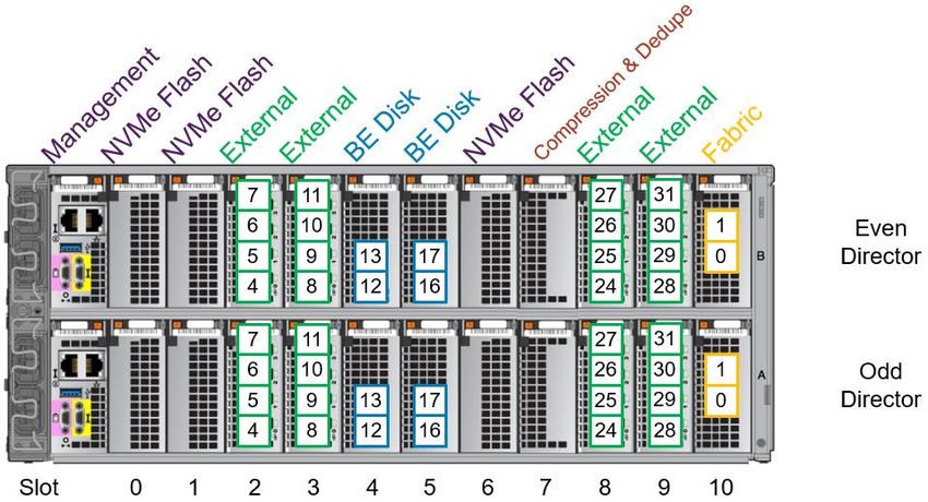
Revisions

Revisions
                                Date                     Description
                 May 2018                Initial release
                 October 2018            Update
                 September 2019 PowerMaxOS 5978 Q3 2019 release updates
                 September 2020 PowerMaxOS 5978 Q3 2020 release updates

Acknowledgments
               Author: Michael Bresnahan

The information in this publication is provided “as is.” Dell Inc. makes no representations or warranties of any kind with respect to the information in this
publication, and specifically disclaims implied warranties of merchantability or fitness for a particular purpose.

Use, copying, and distribution of any software described in this publication requires an applicable software license.

Copyright © 2018–2020 Dell Inc. or its subsidiaries. All Rights Reserved. Dell Technologies, Dell, EMC, Dell EMC and other trademarks are trademarks
of Dell Inc. or its subsidiaries. Other trademarks may be trademarks of their respective owners. [9/15/2020] [Technical White Paper] [H17064.4]

2         Dell EMC PowerMax: Reliability, Availability, and Serviceability | H17064.4
Table of contents

Table of contents
    1    Introduction ...................................................................................................................................................................6
    2    Dell EMC PowerMax system family overview ..............................................................................................................7
    3    PowerMax engine and director components ................................................................................................................8
         3.1      Channel front-end redundancy .........................................................................................................................10
         3.2      Global memory technology overview................................................................................................................12
    4    PowerMax NVMe back end ........................................................................................................................................13
         4.1      Smart RAID.......................................................................................................................................................13
         4.2      RAID 5 ..............................................................................................................................................................14
         4.3      RAID 6 ..............................................................................................................................................................14
         4.4      RAID 1 ..............................................................................................................................................................14
         4.5      Drive sparing.....................................................................................................................................................15
         4.6      Data at Rest Encryption ....................................................................................................................................17
         4.7      T10 Data Integrity Field ....................................................................................................................................17
         4.8      End-to-end efficient encryption .........................................................................................................................18
         4.9      Drive monitoring and correction........................................................................................................................19
    5    InfiniBand fabric switch ...............................................................................................................................................20
    6    Redundant power subsystem .....................................................................................................................................21
         6.1      Vaulting .............................................................................................................................................................22
         6.2      Power-down operation ......................................................................................................................................23
         6.3      Power-up operation ..........................................................................................................................................23
    7    Remote support ..........................................................................................................................................................24
         7.1      Supportability through the management module control station ......................................................................24
         7.2      Secure Service Credential, secured by RSA ....................................................................................................25
    8    Component-level serviceability...................................................................................................................................26
         8.1      Dell Technologies internal QE testing ..............................................................................................................26
    9    Non-Disruptive Upgrades ...........................................................................................................................................28
         9.1      PowerMaxOS upgrades ...................................................................................................................................28
         9.2      eNAS upgrades ................................................................................................................................................28
         9.3      Hardware upgrades ..........................................................................................................................................28
    10 TimeFinder and SRDF replication software ...............................................................................................................30
         10.1 Local replication using TimeFinder ...................................................................................................................30
         10.2 PowerMaxOS Q3 2020 release SnapVX updates............................................................................................30
         10.3 Remote replication using SRDF .......................................................................................................................31
         10.4 PowerMaxOS Q3 2020 release SRDF updates ...............................................................................................33

3           Dell EMC PowerMax: Reliability, Availability, and Serviceability | H17064.4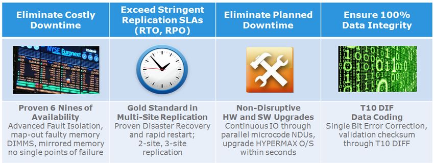
Table of contents

    11 Unisphere for PowerMax and Solutions Enabler .......................................................................................................35
          11.1 Unisphere for PowerMax system health check ................................................................................................35
          11.2 Unisphere alerts................................................................................................................................................36
          11.3 Solutions Enabler commands ...........................................................................................................................37
    12 Summary ....................................................................................................................................................................40
    A     Technical support and resources ...............................................................................................................................41
          A.1      Related resources ............................................................................................................................................41

4            Dell EMC PowerMax: Reliability, Availability, and Serviceability | H17064.4
Executive summary

Executive summary
           Today’s mission-critical environments demand more than redundancy. They require non-disruptive
           operations, non-disruptive upgrades and being “always online.” They require high-end performance, handling
           all workloads, predictable or not, under all conditions. They require the added protection of increased data
           availability provided by local snapshot replication and continuous remote replication.

           Dell EMC™ PowerMax storage arrays deliver these needs. The introduction of NVMe drives raises the
           performance expectations and possibilities of high-end arrays. A simple, service level-based provisioning
           model simplifies the way users consume storage, taking the focus away from the back-end configuration
           steps and allowing them to concentrate on other key roles.

           While performance and simplification of storage consumption are critical, other features also create a
           powerful platform. Redundant hardware components and intelligent software architecture deliver extreme
           performance while also providing high availability. This combination provides exceptional reliability, while also
           leveraging components in ways that decrease the total cost of ownership of each system. Important
           functionality such as local and remote replication of data, used to deliver business continuity, must cope with
           more data than ever before without impacting production activities. Furthermore, at the end of the day, these
           challenges must be met while continually improving data center economics.

           Reliability, availability, and serviceability (RAS) features are crucial for enterprise environments requiring
           always-on availability. PowerMax arrays are architected for six-nines (99.9999%) availability. The many
           redundant features discussed in this document are factored into the calculation of overall system availability.
           This includes redundancy in the back-end, cache memory, front-end, and fabric, as well as the types of RAID
           protections given to volumes on the back-end. Calculations may also include time to replace failed or failing
           FRUs (field replaceable units). In turn, this also considers customer service levels, replacement rates of the
           various FRUs and hot sparing capability in the case of drives.

                         PowerMax RAS highlights

5      Dell EMC PowerMax: Reliability, Availability, and Serviceability | H17064.4
Introduction

1              Introduction
               PowerMax arrays include enhancements that improve reliability, availability, and serviceability. This makes
               PowerMax arrays ideal choices for critical applications and 24x7 environments demanding uninterrupted
               access to information.

               PowerMax array components have a mean time between failure (MTBF) of several hundred thousand to
               millions of hours for a minimal component failure rate. A redundant design allows systems to remain online
               and operational during component replacement. All critical components are fully redundant, including director
               boards, global memory, internal data paths, power supplies, battery backup, and all NVMe back-end
               components. Periodically, the system tests all components. PowerMaxOS reports errors and environmental
               conditions to the host system as well as to the Customer Support Center.

               PowerMaxOS validates the integrity of data at every possible point during the lifetime of the data. From the
               point at which data enters an array, the data is continuously protected by error detection metadata, data
               redundancy, and data persistence. This protection metadata is checked by hardware and software
               mechanisms anytime data is moved within the subsystem, allowing the array to provide true end-to-end
               integrity checking and protection against hardware or software faults. Data redundancy and persistence
               allows recovery of data where the integrity checks fail.

               The protection metadata is appended to the data stream, and contains information describing the expected
               data location as well as CRC representation of the actual data contents. The expected values found in
               protection metadata are stored persistently in an area separate from the data stream. The protection
               metadata is used to validate the logical correctness of data being moved within the array anytime the data
               transitions between protocol chips, internal buffers, internal data fabric endpoints, system cache, and system
               disks.

               PowerMaxOS supports industry standard T10 Data Integrity Field (DIF) block cyclic redundancy code (CRC)
               for track formats. For open systems, this enables a host-generated DIF CRC to be stored with user data and
               used for end-to-end data integrity validation. Additional protections for address or control fault modes provide
               increased levels of protection against faults. These protections are defined in user-definable blocks supported
               by the T10 standard. Address and write status information is stored in the extra bytes in the application tag
               and reference tag portion of the block CRC.

               The objective of this technical note is to provide an overview of the architecture of PowerMax arrays and the
               reliability, availability, and serviceability (RAS) features within PowerMaxOS.

6       Dell EMC PowerMax: Reliability, Availability, and Serviceability | H17064.4
Dell EMC PowerMax system family overview

2          Dell EMC PowerMax system family overview
           The Dell EMC PowerMax 2000 and Dell EMC PowerMax 8000 are the first Dell EMC hardware platforms with
           end-to-end Non-Volatile Memory Express (NVMe); from servers to PowerMax drives (SCM/Flash). PowerMax
           end-to-end NVMe delivers the best response times for high demand applications of today and tomorrow.

           NVMe is the protocol that runs on the PCI Express (PCIe) transport interface, used to efficiently access
           storage devices based on Non-Volatile Memory (NVM) media, including today’s NAND-based flash along with
           future, higher-performing, Storage Class Memory (SCM) media technologies such as 3D XPoint and Resistive
           RAM (ReRAM). NVMe also contains a streamlined command set used to communicate with NVM media,
           replacing SCSI and ATA. NVMe was specifically created to fully unlock the bandwidth, IOPS, and latency
           performance benefits that NVMe offers to host-based applications which are currently unattainable using the
           SAS and SATA storage interfaces.

           32 Gb/s FC-NVMe I/O modules for host connectivity accelerate network bandwidth for massive consolidation.
           The NVMe back-end consists of a 24-slot NVMe DAE using 2.5” form factor drives connected to the Brick
           through dual-ported NVMe PCIe Gen3 (eight lane) back-end I/O interface modules, delivering up to 8 GB/sec
           of bandwidth per module.

           SCM drives based on Intel® Optane™ dual port technology are available for open systems and mainframe
           applications. Dell and Intel combine forces to define enterprise storage media for the next decade. SCM
           technology delivers unmatched levels of performance and consolidation for high value, high demand
           workloads of today and tomorrow.

           In addition to the all-NVMe storage density and scale which provide high back-end IOPS and low latency, the
           Dell EMC PowerMax arrays also introduce a more powerful data reduction module capable of performing
           inline hardware data compression, deduplication, and adaptive tiering to lower TCO by using auto data
           placement.

           Highlights of the PowerMax 2000 system include:

                •   1 to 2 engines per system
                •   12-core Intel Broadwell CPUs yielding 48 cores per engine
                •   Up to 2 TB of DDR4 cache per engine
                •   Up to 64 FE ports per system
                •   Up to 1 PBe per system of PCIe Gen3 NVMe storage

           Highlights of the PowerMax 8000 system include:

                •   1 to 8 engines per system
                •   18-core Intel Broadwell CPUs yielding 72 cores per engine
                •   Up to 2 TB DDR4 cache per engine
                •   Up to 256 FE ports per system
                •   Up to 4 PBe per system of PCIe Gen3 NVMe storage

           The primary benefits that the PowerMax platforms offer Dell EMC customers are:

                •   Massive scale with low latency NVMe design
                •   More storage IOPS density per system in a much smaller footprint
                •   Applied machine learning to lower TCO by using intelligent data placement
                •   Data efficiency and data reduction capabilities with inline dedupe and compression

7      Dell EMC PowerMax: Reliability, Availability, and Serviceability | H17064.4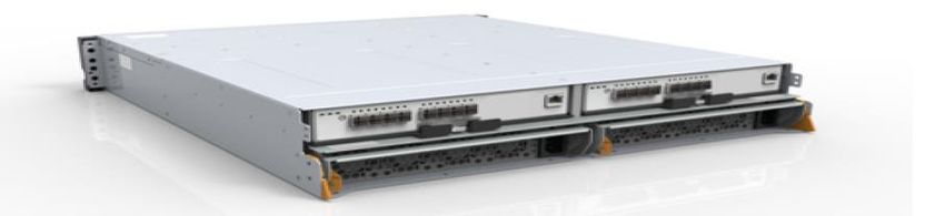
PowerMax engine and director components

3          PowerMax engine and director components
           The engine is the critical building block of PowerMax systems. It primarily consists of two redundant director
           boards that house global memory, front-end connectivity, back-end connectivity, internal network
           communications and environmental monitoring components. Each director board has a dedicated power and
           cooling system. Even single-engine configurations are fully redundant. A PowerMax system may have
           between one and eight engines depending on model and configuration.

           Table 1 lists the components within an engine, count per director, and defines their purposes.

                         PowerMax engine and director components
                     Director                 Count
                                                                                         Purpose
                    Component              (per director)
                   Power Supply                    2         Provide redundant power to a director
                         Fan                       5         Provide cooling for a director
               Management Module                   1         Manage environmental functionality
             NVMe Flash I/O Module             Up to 4       Safely store data from cache during the vaulting sequence.
               Front-end I/O Module            Up to 4       Provide front-end connectivity to the array. There are different
                                                             types of front-end I/O modules that allow connectivity to various
                                                             interfaces, including Fibre Channel SCSI, Fibre Channel NVMe,
                                                             iSCSI, FICON, SRDF, and embedded NAS (eNAS).
                PCIe Back-end I/O                  2         Connect the director boards to the back-end of the system,
                     Module                                  allowing I/O to the system’s drives.
                Compression and                    1         Perform inline data compression and deduplication
             Deduplication I/O Module
                 Fabric I/O module                 1         Provides connectivity between directors. In multi-engine
                                                             PowerMax 8000 systems, the fabric I/O modules are connected
                                                             to an internal InfiniBand switch.
                  Memory module                   16         Global memory component

           Figure 2 displays the front view of a PowerMax engine.

                         Front view of PowerMax 2000 and PowerMax 8000 engine

8      Dell EMC PowerMax: Reliability, Availability, and Serviceability | H17064.4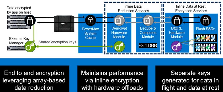
PowerMax engine and director components
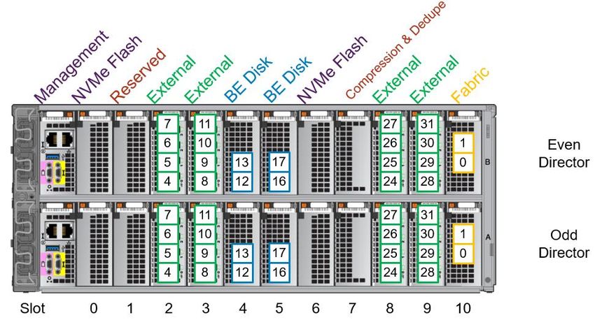
The following figures display back views of engine components, with logical port numbering.
Back view of PowerMax 2000 engine with logical port numbering
Back view of PowerMax 8000 multi-engine with logical port numbering
Back view of PowerMax 8000 single-engine with logical port numbering
9 Dell EMC PowerMax: Reliability, Availability, and Serviceability | H17064.4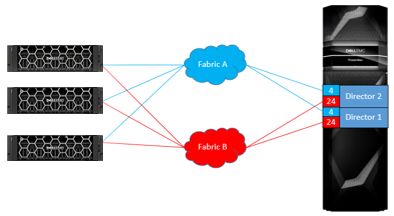
PowerMax engine and director components

           Note that a single-engine PowerMax 8000 system requires four NVMe Flash I/O modules per director
           compared to a multi-engine PowerMax 8000 which requires three NVMe Flash I/O modules per director. The
           four NVMe Flash I/O modules per director configuration will remain even if additional engines are added to
           the system. This must be considered when ordering new systems as the additional NVMe Flash I/O module
           reduces the number of external I/O modules, thus reducing the total number of external ports.

3.1        Channel front-end redundancy
           Channel redundancy is provided by configuring multiple connections from the host servers (direct connect) or
           Fibre Channel switch (SAN connect) to the system. With SAN connectivity, through Fibre Channel switches,
           each front-end port can support multiple host attachments, enabling storage consolidation across many host
           platforms. The multiple connections are distributed across separate directors to ensure uninterrupted access
           in the event of a channel failure. A minimum of two connections per server or SAN to different directors is
           necessary to provide full redundancy.

           Host connectivity to the front-end director ports should be spread across physical components for the most
           efficient form of redundancy.

           The following are recommended for connecting a host or cluster:

                •   2 to 4 front-end paths are configured in the port group for masking and zones to the host (single
                    initiator zoning is recommended).
                •   For cabling options, one approach is to connect all even-numbered ports to fabric A and all odd-
                    numbered ports to fabric B.
                •   In single engine systems with this approach, select 2 I/O ports spanning both SAN fabrics on each
                    director, with each port being on a separate I/O module.

                    Example: Port 4 and 24 on both directors 1 and 2.

                •   In a multi-engine system, distributing the paths further across directors spanning different engines
                    spreads the load for performance and ensures fabric redundancy.

                    Example: Port 4 in directors 1, 2, 3 and 4.

                         SAN connectivity in a single engine environment

10     Dell EMC PowerMax: Reliability, Availability, and Serviceability | H17064.4
PowerMax engine and director components
3.1.1 FC-NVMe front-end redundancy
Recommendation is to follow the same guidelines outlined for previously supported protocols.
The following are recommended for connecting a host or cluster:
• 2 to 4 front-end paths are configured in the port group for masking and zones to the host (single
initiator zoning is recommended).
• For cabling options, one approach is to connect all even-numbered ports to fabric A and all odd-
numbered ports to fabric B.
• In single engine systems with this approach, select 2 I/O ports spanning both SAN fabrics on each
director, with each port being on a separate I/O module.
Example: Port 4 and 24 on both directors 1 and 2.
In a multi-engine system, distributing the paths further across directors spanning different engines spreads
the load for performance and ensures fabric redundancy.
NVMe devices are supported with PowerPath 7.0 releases providing enhance multi-pathing with flake path
and congestion controls that yield higher IOPS over native operating-system multipathing.
3.1.2 Dell EMC PowerPath Intelligent Multipathing Software
Dell EMC PowerPath is a family of software products that ensures consistent application availability and
performance across I/O paths on physical and virtual platforms.
It provides automated path management and tools that enable you to satisfy aggressive service-level
agreements without investing in additional infrastructure. PowerPath includes PowerPath Migration Enabler
for non-disruptive data migrations and PowerPath Viewer for monitoring and troubleshooting I/O paths.
Dell EMC PowerPath/VE is compatible with VMware vSphere and Microsoft Hyper-V-based virtual
environments. It can be used together with Dell EMC PowerPath to perform the following functions in both
physical and virtual environments:
• Standardize Path Management: Optimize I/O paths in physical and virtual environments
(PowerPath/VE) as well as cloud deployments.
• Optimize Load Balancing: Adjust I/O paths to dynamically rebalance your application environment
for peak performance.
• Increase Performance: Leverage your investment in physical and virtual environment by increasing
headroom and scalability.
• Automate Failover and Recovery: Define failover and recovery rules that route application requests
to alternative resources in the event of component failures or user errors.
For more information about PowerPath, refer to the Dell EMC PowerPath Family Product Guide.
11 Dell EMC PowerMax: Reliability, Availability, and Serviceability | H17064.4PowerMax engine and director components
3.2 Global memory technology overview
Global memory is a crucial component in the architecture. All read and write operations are transferred to and
from global memory. Transfers between the host processor and channel directors can be processed at much
greater speeds than transfers involved with hard drives. PowerMaxOS uses complex statistical prefetch
algorithms which can adjust to proximate conditions on the array. Intelligent algorithms adjust to the workload
by constantly monitoring, evaluating, and optimizing cache decisions.
PowerMax arrays can have up to 2 TB of mirrored DDR4 memory per engine and up to 16 TB mirrored per
array. Global memory within an engine is accessible by any director within the array.
Dual-write technology is maintained by the array. Front-end writes are acknowledged when the data is written
to mirrored locations in the cache. In the event of a director or memory failure, the data continues to be
available from the redundant copy. If an array has a single engine, physical memory mirrored pairs are
internal to the engine. Physical memory is paired across engines in multi-engine PowerMax 8000 arrays.
3.2.1 Physical memory error verification and error correction
PowerMaxOS can correct single-bit errors and report an error code once the single-bit errors reach a
predefined threshold. To protect against possible future multi-bit errors, if single-bit error rates exceed a
predefined threshold, the physical memory module is marked for replacement. When a multi-bit error occurs,
PowerMaxOS initiates director failover and calls out the appropriate memory module for replacement.
When a memory module needs to be replaced, the array notifies Dell Support and a replacement is ordered.
The failed module is then sent back to Dell Support for failure analysis.
12 Dell EMC PowerMax: Reliability, Availability, and Serviceability | H17064.4PowerMax NVMe back end
4 PowerMax NVMe back end
The PowerMax architecture incorporates an NVMe back end that reduces command latency and increases
data throughput while maintaining full redundancy. NVMe is an interface that allows host software to
communicate with a nonvolatile memory subsystem. This interface is optimized for Enterprise and Client
solid-state drives (SSDs), typically attached as a register-level interface to the PCI Express interface.
The NVMe back-end subsystem provides redundant paths to the data stored on solid-state drives. This
provides seamless access to information, even in the event of a component failure or replacement.
Each PowerMax Drive Array Enclosure (DAE) can hold 24 x 2.5” NVMe SSDs. The DAE also houses
redundant Canister Modules (Link Control Cards) and redundant AC/DC power supplies with integrated
cooling fans. Figure 7 and Figure 8 show the front and back views of the PowerMax DAE.
PowerMax DAE (front)
PowerMax DAE (back)
The directors are connected to each DAE through a pair of redundant back-end I/O modules. The back-end
I/O modules connect to the DAEs at redundant LCCs. Each connection between a back-end I/O module and
an LCC uses a completely independent cable assembly. Within the DAE, each NVMe drive has two ports,
each of which connects to one of the redundant LCCs.
The dual-initiator feature ensures continuous availability of data in the unlikely event of a drive management
hardware failure. Both directors within an engine connect to the same drives using redundant paths. If the
sophisticated fencing mechanisms of PowerMaxOS detect a failure of the back-end director, the system can
process reads and writes to the drives from the other director within the engine without interruption.
4.1 Smart RAID
Smart RAID provides active/active shared RAID support for PowerMax arrays. Smart RAID allows RAID
groups to be shared between back-end directors within the same engine. Each back-end director has access
to every hard drive within the DAE but each TDAT on that hard drive will be primary to only one back-end
director.
Smart RAID helps in cost reduction by allowing a smaller number of RAID groups while improving
performance by allowing two directors to run I/O concurrently to the same set of drives.
Figure 9 illustrates Smart RAID connectivity between directors, spindles, and TDATs.
13 Dell EMC PowerMax: Reliability, Availability, and Serviceability | H17064.4PowerMax NVMe back end
Smart RAID connectivity
4.2 RAID 5
RAID 5 is an industry-standard data protection mechanism with rotating parity across all members of the
RAID 5 set. In the event of a hard drive failure, the missing data is rebuilt by reading the remaining drives in
the RAID group and performing XOR calculations.
PowerMax systems support two RAID 5 configurations:
• RAID 5 (3+1) – Data striped across 4 drives (3 data, 1 parity)
• RAID 5 (7+1) – Data striped across 8 drives (7 data, 1 parity)
4.3 RAID 6
RAID 6 enables the rebuilding of data if two drives fail within a RAID group. Our implementation of RAID 6
calculates two types of parity. This is important during events when two drives within the same RAID group
fail, as it still allows the data in this scenario to be reconstructed. Horizontal parity is identical to RAID 5 parity,
which is calculated from the data across all disks in the RAID group. Diagonal parity is calculated on a
diagonal subset of data members. For applications without demanding performance needs, RAID 6 provides
the highest data availability.
PowerMax systems support RAID 6 (6+2) with data striped across 8 drives (6 data, 2 parity).
4.4 RAID 1
RAID 1 is an industry-standard data protection consisting of two drives containing exact copies, or mirrors, of
the data. There is no parity required as both RAID members have full copies of the data allowing the system
to retrieve data from either disk. Dell EMC PowerMax implements RAID 1 (1 + 1) mirroring the data across
two drives.
RAID 1 is available on PowerMax arrays with the PowerMaxOS Q3 2020 release and later.
14 Dell EMC PowerMax: Reliability, Availability, and Serviceability | H17064.4PowerMax NVMe back end
4.5 Drive sparing
PowerMaxOS supports Universal Sparing to automatically protect a failing drive with a spare drive. Universal
Sparing increases data availability of all volumes in use without loss of any data capacity, transparently to the
host, and without user intervention.
When PowerMaxOS detects a drive is failing, the data on the faulty drive is copied directly to a spare drive
attached to the same engine. If the faulty drive has failed, the data is rebuilt onto the spare drive through the
remaining RAID members. When the faulty drive is replaced, data is copied from the spare to the new drive.
4.5.1 Spare drive count
PowerMax systems have one spare drive in each engine. The spare drives reside in dedicated DAE slots.
The spare drive type is the same as the highest capacity and performance class as the other drives in the
engine.
Modern, solid state drives have a longer life than spinning disks of the past and have advanced feedback
mechanisms that allow for proactive sparing and replacement before a failure occurs. The PowerMax spare
drive count requirement was determined after thorough analysis and there is no need to configure additional
spare drives.
4.5.2 Solutions Enabler commands
Solutions Enabler provides tools to view information related to spare drives in PowerMax arrays.
The symcfg list –v output reports total values for Configured Actual Disks, Configured Spare Disks and
Available Spare Disks in the system.
The Number of Configured Actual Disks field reports only non-spare configured disks, and Number
of Configured Spare Disks field reports only configured spare disks.
The following shows the command symcfg -sid list -v:
Symmetrix ID: 000197600XYZ (Local)
Time Zone : Eastern Standard Time
Product Model : PowerMax_8000
Symmetrix ID : 000197600XYZ
Microcode Version (Number) : 5978 (175A0000)
--------------------< TRUNCATED >-------------------------
Number of Configured Actual Disks : 64
Number of Configured Spare Disks : 2
Number of Available Spare Disks : 2
15 Dell EMC PowerMax: Reliability, Availability, and Serviceability | H17064.4PowerMax NVMe back end
The symdisk list –dskgrp_summary –by_engine reports spare coverage information per Disk Group
per Engine. The -detail and -v options will provide additional information.
The Total and Available spare disk counts for each Disk Group include both spare disks that are in the same
Disk Group in the same Engine, as well as shared spare disks in another Disk Group in the same Engine that
provide acceptable spare coverage. These shared spares are also included in the total disk count for each
Disk Group in each Engine. Therefore, the cumulative values of all Disk Groups in all Engines in this output
should not be expected to match the values reported by the symcfg list –v command that were
described in the previous example.
Total Disk Spare Coverage percentage for a Disk Group is the spare capacity in comparison to usable
capacity shown in the output.
The following shows the command symdisk -sid list –dskgrp_summary –by_engine:
Disk Hyper Usable Capacity Spare Coverage
------------------------ ------- ------------------- -----------------
Flgs Speed Size Total Total Avail
Grp Eng Cnt LT (RPM) (MB) Disk (%) (MB) Disk (%) Disk (%)
---- --- ---- ---- ----- ------- ---- --- ---------- ---- --- ---- ---
1 1 9 IE 0 29063 8 89 14880255 1 12 1 100
2 1 25 IE 0 29063 24 96 44640765 1 4 1 100
2 2 33 IE 0 29063 32 97 59521020 1 3 1 100
---- --- ----------
Total 64 97 119042040
Legend:
Disk (L)ocation:
I = Internal, X = External, - = N/A
(T)echnology:
S = SATA, F = Fibre Channel, E = Enterprise Flash Drive, - = N/A
Spare Coverage as reported by the symdisk list –v and symdisk show commands indicates whether
the disk currently has at least one available spare; that is, a spare disk that is not in a failed state or already
invoked to another disk.
The following shows the command symdisk -sid list –v:
Symmetrix ID : 000197600XYZ
Disks Selected : 66
Director : DF-1C
Interface : C
Target ID : 0
Spindle ID : 0
--------------------< TRUNCATED >-------------------------
Spare Disk : N/A
Spare Coverage : True
16 Dell EMC PowerMax: Reliability, Availability, and Serviceability | H17064.4PowerMax NVMe back end
4.6 Data at Rest Encryption
Data at Rest Encryption (D@RE) protects data confidentiality by adding back-end encryption to the entire
array. D@RE provides hardware-based, on-array, back-end encryption. Back-end encryption protects
information from unauthorized access when drives are removed from the system.
D@RE provides encryption on the back-end that incorporate XTS-AES 256-bit data-at-rest encryption. These
I/O modules encrypt and decrypt data as it is being written to or read from a drive. All configured drives are
encrypted, including data drives, spares, and drives with no provisioned volumes.
D@RE incorporates RSA™ Embedded Key Manager for key management. With D@RE, keys are self-
managed, and there is no need to replicate keys across volume snapshots or remote sites. RSA Embedded
Key Manager provides a separate, unique Data Encryption Key (DEK) for each drive in the array, including
spare drives.
By securing data on enterprise storage, D@RE ensures that the potential exposure of sensitive data on
discarded, misplaced, or stolen media is reduced or eliminated. If the key used to encrypt the data is secured,
encrypted data cannot be read. In addition to protecting against threats related to physical removal of media,
media can readily be repurposed by destroying the encryption key used for securing the data previously
stored on that media.
D@RE:
• Is compatible with all PowerMaxOS features.
• Allows for encryption of any supported local drive types or volume emulations.
• Delivers powerful encryption without performance degradation or disruption to existing applications or
infrastructure.
D@RE can also be deployed with external key managers using Key Management Interoperability Protocol
(KMIP) that allow for a separation of key management from PowerMax arrays. KMIP is an industry standard
that defines message formats for the manipulation of cryptographic keys on a key management server.
External key manager provides support for consolidated key management and allows integration between a
PowerMax array with an already existing key management infrastructure.
For more information about D@RE, see the following documents:
• Dell EMC PowerMax Family Security Configuration Guide
• Dell EMC VMAX3 and VMAX All Flash Data at Rest Encryption White Paper
4.7 T10 Data Integrity Field
PowerMaxOS supports industry standard T10 Data Integrity Field (DIF) block cyclic redundancy code (CRC)
for track formats. For open systems, this enables a host-generated DIF CRC to be stored with user data and
used for end-to-end data integrity validation. Additional protections for address and control fault modes
provide increased levels of protection against faults. These protections are defined in user-definable blocks
supported by the T10 standard. Address and write status information is stored in the extra bytes in the
application tag and reference tag portion of the block CRC.
PowerMaxOS further increases data integrity with T10-DIF+ which has additional bits for detecting stale data
address faults, control faults and sector signature faults that are not detected in a standard T10-DIF. T10-
DIF+ is performed every time data is moved; across the internal fabric, to or from drives, and on the way back
to the host on reads.
17 Dell EMC PowerMax: Reliability, Availability, and Serviceability | H17064.4PowerMax NVMe back end
On the backend, the T10-DIF codes for the expected data is stored and the checksums are verified when the
data is read from the host. In addition, a one-byte checksum for each 8 K of data is kept in the track table (not
stored with the data) that is used for independent validation of the data against the last version written to the
array. This provides protection against situations such as:
• Detecting reads from the wrong block: The data and checksum stored together are fine, but it was
from the wrong address. In this case, the additional checksum will not match.
• RAID disagreement: Each data block and the parity block of the RAID group have valid checksums
and no errors, but the parity does not match with the data. In this case, each of the data blocks can
be validated to determine if a data block or the parity block are stale.
4.8 End-to-end efficient encryption
The PowerMaxOS Q3 2020 release introduced the availability of end-to-end efficient encryption which
increases security by encrypting data at the host level while also looking for maximum data reduction on the
PowerMax array.
The functionality is provided by integration with the following Thales Security software:
• Vormetric Transparent Encryption (VTE) – Agent or driver which runs on the customers’ hosts.
• Data Security Manager (DSM) – Key Manager available as an appliance and in a software version
that can be run on the customer’s server.
Thales Security software can be obtained directly from Thales Security (https://www.thalesesecurity.com/) or
through Dell.
End-to-end efficient encryption also requires a specific type of front-end I/O module per PowerMax director.
End-to-end efficient encryption can be added to pre-existing PowerMax arrays that are D@RE enabled and
have a free front-end I/O slot per director to accommodate the addition of the dedicated I/O module
Configuring end-to-end efficient encryption on an array allows encryption to be set on selective volumes at the
volume level, including selective volumes within a Storage Group.
The encryption-capable attribute is set during volume creation. This attribute cannot be set or unset on
existing volumes. However, setting this attribute does not require the volume to participate in encryption.
Volumes with the attribute set then need to be guarded to participate in encryption.
Guarding a volume requires a VTE enabled host and access to set policy on the DSM. Guarding an
encryption capable volume activates encryption for all I/O and will encrypt all new data written to the volume,
not data that already resides on the volume.
A guarded volume can later be unguarded. Any new I/O will not be encrypted. Existing data on the volume is
not unencrypted. Any encrypted data read back to the host will remain in its encrypted state.
18 Dell EMC PowerMax: Reliability, Availability, and Serviceability | H17064.4PowerMax NVMe back end
Figure 10 is an overview of the end-to-end efficient encryption operational flow.
End-to-end efficient encryption
For more information about PowerMax end-to-end efficient encryption, see the DSM Deployment Guide.
4.9 Drive monitoring and correction
PowerMaxOS monitors media defects by both examining the result of each data transfer and proactively
scanning the entire drive during idle time. If a block is determined to be bad, the director:
• Rebuilds the data in physical memory if necessary.
• Remaps the defective block to another area on the drive set aside for this purpose.
• Rewrites the data from physical memory back to the remapped block on the drive.
The director maps around any bad blocks detected, thereby avoiding defects in the media. The director also
keeps track of each bad block detected. If the number of bad blocks exceeds a predefined threshold, the
primary MMCS invokes a sparing operation to replace the defective drive and then automatically alerts
Customer Support to arrange for corrective action.
19 Dell EMC PowerMax: Reliability, Availability, and Serviceability | H17064.4InfiniBand fabric switch
5 InfiniBand fabric switch
Multi-engine PowerMax 8000 systems employ two 18-port InfiniBand fabric switches to carry control,
metadata, and user data through the system. This technology connects all engines in the system to provide a
powerful form of redundancy and performance. This allows the engines to share resources and act as a
single entity while communicating.
For redundancy, each director has a connection to each switch. Each switch has redundant, hot pluggable
power supplies. Figure 11 and Figure 12 show the front and back views of the InfiniBand switches.
Front view of InfiniBand switch
Back view of InfiniBand switch
Note: Since the purpose of the dynamic virtual matrix is to create a communication interconnection between
all engines, single-engine systems and dual-engine PowerMax 2000 systems do not require a fabric switch.
20 Dell EMC PowerMax: Reliability, Availability, and Serviceability | H17064.4Redundant power subsystem
6 Redundant power subsystem
A modular power subsystem features a redundant architecture that facilitates field replacement of any of its
components without any interruption in processing.
The power subsystem has two power zones for redundancy. Each power zone connects to a separate
dedicated or isolated AC power line. If AC power fails on one zone, the power subsystem continues to
operate through the other power zone. If any single power supply module fails, the remaining power supplies
continue to share the load. PowerMaxOS senses the fault and reports it as an environmental error.
Each director is configured with a management module that provides low-level, system-wide communications
and environmental control for running application software, monitoring, and diagnosing the system. The
management modules are responsible for monitoring and reporting any environmental issues, such as power,
cooling, or connectivity problems.
Environmental information is carried through two redundant Ethernet switches. Each management module
connects to one switch, except for the MMCS modules in Engine 1 which connect to both Ethernet switches.
Management module A connects to Ethernet switch A, and management module B connects to Ethernet
switch B. Each management module also monitors one of the system standby power supplies (SPS) through
an RS232 connection. Standard PowerMax 8000 racks have LED bars that are connected to the
management modules and are used for system or bay identification during service activities.
Figure 13 illustrates management module connectivity.
LED Bar
Management module connectivity
The internal Ethernet connectivity network monitors and logs environmental events across all critical
components and reports any operational problems. Critical components include director boards, global
memory, power supplies, power line input modules, fans, and various power switches. The network’s
environmental control capability can monitor each component’s local voltages, ensuring optimum power
delivery. Temperature of director boards and memory are also continuously monitored. Failing components
can be detected and replaced before a failure occurs.
21 Dell EMC PowerMax: Reliability, Availability, and Serviceability | H17064.4Redundant power subsystem
The AC power main is checked for the following:
• AC failures
• Power loss to a single power zone
• DC failures
• Current sharing between DC supplies
• DC output voltage
• Specific notification of overvoltage condition
• Current from each DC supply
• Voltage drops across major connectors
Figure 14 illustrates the internal Ethernet connectivity.
Internal Ethernet connectivity
6.1 Vaulting
As cache size has grown, the time required to move all cached data to a persistent state has also increased.
Vaulting is designed to limit the time needed to power off the system if it needs to switch to a battery supply.
Upon complete system power loss or transitioning a system to an offline state, PowerMaxOS performs a vault
of cache memory to dedicated I/O modules known as flash I/O modules. The flash I/O modules use NVMe
technology to safely store data in cache during the vaulting sequence.
Lithium-ion standby power supply (Li-ion SPS) modules provide battery backup functionality during the vault
operation. Two SPS modules are configured per engine. The SPS modules also provide back-up power to the
InfiniBand switches in applicable configurations.
6.1.1 Vault triggers
State changes that require the system to vault are referred to as vault triggers. There are two types of vault
triggers: internal availability triggers and external availability triggers.
6.1.1.1 Internal availability triggers
Internal availability triggers are initiated when global memory data becomes compromised due to component
unavailability. Once these components become unavailable, the system triggers the Need to Vault (NTV)
state, and vaulting occurs. There are three internal triggers:
Vault flash availability: The NVMe flash I/O modules are used for storage of metadata under normal
conditions, as well as storing any data that is being saved during the vaulting process. PowerMax systems
22 Dell EMC PowerMax: Reliability, Availability, and Serviceability | H17064.4Redundant power subsystem
can withstand failure and replacement of flash I/O modules without impact to processing. However, if the
overall available flash space in the system is reduced to the minimum to be able to store the required copies
of global memory, the NTV process triggers. This is to ensure that all data is saved before a potential further
loss of vault flash space occurs.
Global memory (GM) availability: When any of the mirrored director pairs are both unhealthy either logically
or environmentally, NTV triggers because of GM unavailability.
Fabric availability: When both the fabric switches are environmentally unhealthy, NTV triggers because of
fabric unavailability.
6.1.1.2 External availability triggers
External availability triggers are initiated under circumstances when global memory data is not compromised,
but it is determined that the system preservation is improved by vaulting. There are three external triggers:
Input power: If power is lost to both power zones, the system vaults.
Engine trigger: If an entire engine fails, the system vaults.
DAE trigger: If the system has lost access to the whole DAE or DAEs, including dual-initiator failure, and loss
of access causes configured RAID members to become non-accessible, the system vaults.
6.2 Power-down operation
When a system is powered down or transitioned to offline, or when environmental conditions trigger a vault
situation, a vaulting procedure occurs. First, the part of global memory that is saved reaches a consistent
image (no more writes). The directors then write the appropriate sections of global memory to the flash I/O
modules, saving multiple copies of the logical data. The SPS modules maintain power to the system during
the vaulting process for up to 5 minutes.
6.3 Power-up operation
During power-up, the data is written back to global memory to restore the system. When the system is
powered-on, the startup program does the following:
• Initializes the hardware and the environmental system
• Restores the global memory from the saved data while checking the integrity of the data. This is
accomplished by taking sections from each copy of global memory that was saved during the power-
down operation and combining them into a single complete copy of global memory. If there are any
data integrity issues in a section of the first copy that was saved, then that section is extracted from
the second copy during this process.
• Performs a cleanup, data structure integrity, and initialization of needed global memory data
structures
At the end of the startup program, the system resumes normal operation when the SPS modules are
recharged enough to support another vault operation. If any condition is not safe, the system does not resume
operation and calls Customer Support for diagnosis and repair. In this state, Dell Support can communicate
with the system and find out the reason for not resuming normal operation.
23 Dell EMC PowerMax: Reliability, Availability, and Serviceability | H17064.4Remote support
7 Remote support
Remote support is an important and integral part of Dell EMC Customer Support. Every PowerMax system
has two integrated Management Module Control Stations (MMCS) that continuously monitor the PowerMax
environment. The MMCS modules can communicate with the Customer Support Center through a network
connection to the Secure Remote Support Gateway.
Through the MMCS, the system actively monitors all I/O operations for errors and faults. By tracking these
errors during normal operation, PowerMaxOS can recognize patterns of error activity and predict a potential
hard failure before it occurs. This proactive error tracking capability can often prevent component failures by
fencing off, or removing from service, a suspect component before a failure occurs.
To provide remote support capabilities, the system is configured to call home and alert Dell Support of a
potential failure. An authorized Dell Support Engineer can run system diagnostics remotely for further
troubleshooting and resolution. Configuring Dell EMC products to allow inbound connectivity also enables Dell
Support to proactively connect to the systems to gather needed diagnostic data or to attend to identified
issues. The current connect-in support program for the system uses the latest digital key exchange
technology for strong authentication, layered application security, and a centralized support infrastructure that
places calls through an encrypted tunnel between Customer Support and the MMCS located inside the
system.
Before anyone from Customer Support can initiate a connection to a system at the customer site, that person
must be individually authenticated and determined to be an appropriate member of the Customer Support
team. Field-based personnel who might be known to the customer must still be properly associated with the
specific customer’s account.
An essential part of the design of the connectivity support program is that the connection must originate from
one of several specifically designed Remote Support Networks at Dell Technologies. Within each of those
Support Centers, the necessary networking and security infrastructure has been built to enable both the call-
home and call-device functions.
7.1 Supportability through the management module control station
Each PowerMax system has two management module control stations (MMCS) in the first engine of each
system (one per director). The MMCS combines the management module and control station (service
processor) hardware into a single module. It provides environmental monitoring capabilities for power,
cooling, and connectivity. Each MMCS monitors one of the system standby power supplies (SPS) through an
RS232 connection. Each MMCS is also connected to both internal Ethernet switches within the system as
part of the internal communications and environmental control system.
The MMCS also provides remote support functionality. Each MMCS connects to the customer’s local area
network (LAN) to allow monitoring of the system, as well as remote connectivity for the Dell EMC Customer
Support team. Each MMCS can also be connected to an external laptop or KVM source.
The MMCS located in director 1 is known as the primary MMCS, and the MMCS located in director 2 is known
as the secondary MMCS. The primary MMCS provides all control station functionality when it is operating
normally, while the secondary MMCS provides a subset of this functionality. If the primary MMCS fails, the
secondary MMCS is put in an elevated secondary state, which allows more functionality for the duration of
this state. Both MMCS are connected to the customer network, giving the system the redundant ability to
report any errors to Dell Support, as well as allowing Dell Support to connect to the system remotely.
24 Dell EMC PowerMax: Reliability, Availability, and Serviceability | H17064.4Remote support
The MMCS is used in the following support and maintenance tasks:
• PowerMaxOS upgrade procedures
• Hardware upgrade procedures
• Internal scheduler tasks that monitor the health of the system
• Error collection, logging, and reporting through the call-home feature
• Remote connectivity and troubleshooting by Dell EMC Customer Support
• Component replacement procedures
The MMCS also controls the LED bars on the front and back of each standard PowerMax 8000 rack. These
can be used for system identification purposes by remote and on-site Dell Technologies service personnel.
Figure 15 illustrates MMCS connectivity.
LED Bar
MMCS connectivity
7.2 Secure Service Credential, secured by RSA
The Secure Service Credential (SSC) technology applies exclusively to service processor activities and not
host-initiated actions on array devices. These service credentials describe who is logging in, the capabilities
they have, a time period that the credential is good for, and the auditing of actions the service personnel
performed which can be found in the symaudit logs. If these credentials are not validated, the user cannot log
in to the MMCS or other internal functions. SSC covers both on-site and remote login.
Some of the security features are transparent to the customer, such as service access authentication and
authorization by Dell Support and SC (user ID information) restricted access (MMCS and Dell Support internal
functions). Access is definable at a user level, not just at a host level. All user ID information is encrypted for
secure storage within the array.
MMCS-based functions honor Solutions Enabler Access Control settings per authenticated user to limit the
view or control of non-owned devices in shared environments such as SRDF-connected systems.
25 Dell EMC PowerMax: Reliability, Availability, and Serviceability | H17064.4Component-level serviceability
8 Component-level serviceability
PowerMax systems provide full component-level redundancy to protect against a component failure and
ensure continuous and uninterrupted access to information. This non-disruptive replacement capability allows
the Customer Support Engineer to install a new component, initialize it if necessary, and bring it online without
stopping system operation, taking unaffected channel paths offline, or powering the unit down.
A modular design improves serviceability by allowing non-disruptive component replacements, should a
failure occur. This low parts count minimizes the number of failure points.
PowerMax systems feature non-disruptive replacement of all major components, including:
• Engine components:
- Director boards
- I/O Modules
> Fibre Channel (front-end)
> Embedded NAS (eNAS)
> PCIe (back-end)
> Flash (Vault)
> SRDF Compression
> Inline Compression and Deduplication
> Fabric
- Management modules or management module control stations
- Power supplies
- Fans
• Drive Array Enclosure (DAE) components:
- NVMe drives
- Link Control Cards (LCC)
- Power supplies
- PCIe cables
• Cabinet Components
- InfiniBand switches
- Ethernet switches
- Standby Power Supplies (SPS)
- Power Distribution Units (PDU)
8.1 Dell Technologies internal QE testing
The Dell Technologies Quality Engineering (QE) teams perform thorough testing of all FRUs. Each FRU is
tested multiple times for each code level with very specific pass or fail criteria.
Standard tests perform verification of the GUI-based scripted replacement procedures that are used by Dell
Technologies field personnel. The tests are designed to verify the replaceability of each FRU without any
adverse effects on the rest of the system, and to verify the functionality and ease-of-use of the scripted
procedures. These tests are straightforward replacement procedures performed on operational components.
26 Dell EMC PowerMax: Reliability, Availability, and Serviceability | H17064.4You can also read