Oracle Communications - EAGLE EIR User's Guide - Release 46.9 - Oracle Help Center
←
→
Page content transcription
If your browser does not render page correctly, please read the page content below
Oracle® Communications
EAGLE EIR User's Guide

   Release 46.9
   F27983-01
   August 2020
Oracle Communications EAGLE EIR User's Guide, Release 46.9

F27983-01

Copyright © 1993, 2020, Oracle and/or its affiliates.

This software and related documentation are provided under a license agreement containing restrictions on
use and disclosure and are protected by intellectual property laws. Except as expressly permitted in your
license agreement or allowed by law, you may not use, copy, reproduce, translate, broadcast, modify, license,
transmit, distribute, exhibit, perform, publish, or display any part, in any form, or by any means. Reverse
engineering, disassembly, or decompilation of this software, unless required by law for interoperability, is
prohibited.

The information contained herein is subject to change without notice and is not warranted to be error-free. If
you find any errors, please report them to us in writing.

If this is software or related documentation that is delivered to the U.S. Government or anyone licensing it on
behalf of the U.S. Government, then the following notice is applicable:

U.S. GOVERNMENT END USERS: Oracle programs (including any operating system, integrated software,
any programs embedded, installed or activated on delivered hardware, and modifications of such programs)
and Oracle computer documentation or other Oracle data delivered to or accessed by U.S. Government
end users are "commercial computer software" or “commercial computer software documentation” pursuant
to the applicable Federal Acquisition Regulation and agency-specific supplemental regulations. As such,
the use, reproduction, duplication, release, display, disclosure, modification, preparation of derivative works,
and/or adaptation of i) Oracle programs (including any operating system, integrated software, any programs
embedded, installed or activated on delivered hardware, and modifications of such programs), ii) Oracle
computer documentation and/or iii) other Oracle data, is subject to the rights and limitations specified in the
license contained in the applicable contract. The terms governing the U.S. Government’s use of Oracle cloud
services are defined by the applicable contract for such services. No other rights are granted to the U.S.
Government.

This software or hardware is developed for general use in a variety of information management applications.
It is not developed or intended for use in any inherently dangerous applications, including applications that
may create a risk of personal injury. If you use this software or hardware in dangerous applications, then you
shall be responsible to take all appropriate fail-safe, backup, redundancy, and other measures to ensure its
safe use. Oracle Corporation and its affiliates disclaim any liability for any damages caused by use of this
software or hardware in dangerous applications.

Oracle and Java are registered trademarks of Oracle and/or its affiliates. Other names may be trademarks of
their respective owners.

Intel and Intel Inside are trademarks or registered trademarks of Intel Corporation. All SPARC trademarks are
used under license and are trademarks or registered trademarks of SPARC International, Inc. AMD, Epyc,
and the AMD logo are trademarks or registered trademarks of Advanced Micro Devices. UNIX is a registered
trademark of The Open Group.

This software or hardware and documentation may provide access to or information about content, products,
and services from third parties. Oracle Corporation and its affiliates are not responsible for and expressly
disclaim all warranties of any kind with respect to third-party content, products, and services unless otherwise
set forth in an applicable agreement between you and Oracle. Oracle Corporation and its affiliates will not
be responsible for any loss, costs, or damages incurred due to your access to or use of third-party content,
products, or services, except as set forth in an applicable agreement between you and Oracle.
Contents

1   Introduction
    Overview                                                     1-1
    References                                                   1-1
    Acronyms and Terminology                                     1-1

2   Feature Description
    Equipment Identity Register Overview                         2-1
    EIR Call Flows                                               2-2
        EIR List Determination                                   2-5
    EIR Protocol                                                 2-6
        Check_IMEI Message Handling                              2-7
    EIR List Log File                                            2-8
    Additional EIR Data Files                                   2-10
    EIR S13/S13' Interface Support (Diameter EIR/DEIR)          2-11
        EIR S13 Connection States                               2-11
        S13 Supported Messages                                  2-13
        S13 Supported AVPs                                      2-14
        EIR S13/S13' Interface Support - ECA Message Encoding   2-17
        EIR S13/S13' Interface Support Result Codes             2-18
    DEIR on SLIC Network Redundancy Enhancement                 2-18
    Hardware Requirements                                       2-21
    MPS/EPAP Platform                                           2-25

3   EAGLE EIR Commands
    EAGLE Commands for EIR                                       3-1
        EAGLE EIR GSM Options Commands                           3-1
        EAGLE EIR Service Selector Commands                      3-4
        EAGLE Feature Control Commands                           3-4
        EIR S13/S13' Interface Support Commands                  3-5

                                                                  iii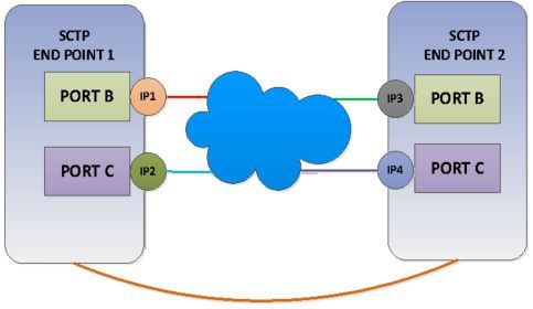
4   EIR Configuration
    Introduction                                                                    4-1
    EPAP Entity Provisioning                                                        4-1
    System Prerequisites                                                            4-1
    EIR Feature Prerequisites                                                       4-2
    EIR Configuration Procedure                                                     4-3
    Enabling and Turning On the EIR Feature                                         4-4
    Provisioning the EIR Local Subsystem                                            4-5
        Adding the EIR Subsystem Application                                        4-6
        Removing the EIR Subsystem Application                                      4-7
    Changing the State of a Subsystem Application                                   4-8
        Taking the Subsystem Application Online                                     4-9
        Taking the Subsystem Application Offline                                   4-10
    Provisioning the EIR Service Selectors                                         4-11
        Adding an EIR Service Selector                                             4-11
        Removing a Service Selector                                                4-12
        Changing an Existing Non-EIR Service Selector to an EIR Service Selector   4-13
    Changing the EIR Options                                                       4-15
    Configuring EIR S13/S13’ Interface Support (Diameter EIR/DEIR)                 4-16
    Configuring DEIR on SLIC                                                       4-17
    Activating the EIR Local Subsystem                                             4-18

5   Maintenance
    EIR Alarms                                                                      5-1
    EIR UIMs                                                                        5-2
    Maintenance Commands                                                            5-5
        rept-stat-sccp                                                              5-6
    EAGLE Debug Commands                                                            5-7
    Status Reporting and Problem Identification                                     5-8
        EPAP Status and Alarm Reporting                                             5-9

6   EIR Measurements
    EIR Measurements                                                                6-1

                                                                                     iv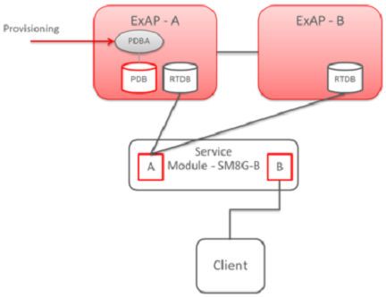
My Oracle Support (MOS)
      My Oracle Support (MOS) is your initial point of contact for any of the following
      requirements:
      •    Product Support:
           The generic product related information and resolution of product related queries.
      •    Critical Situations
           A critical situation is defined as a problem with the installed equipment
           that severely affects service, traffic, or maintenance capabilities, and requires
           immediate corrective action. Critical situations affect service and/or system
           operation resulting in one or several of these situations:
           –   A total system failure that results in loss of all transaction processing capability
           –   Significant reduction in system capacity or traffic handling capability
           –   Loss of the system’s ability to perform automatic system reconfiguration
           –   Inability to restart a processor or the system
           –   Corruption of system databases that requires service affecting corrective
               actions
           –   Loss of access for maintenance or recovery operations
           –   Loss of the system ability to provide any required critical or major trouble
               notification
           Any other problem severely affecting service, capacity/traffic, billing, and
           maintenance capabilities may be defined as critical by prior discussion and
           agreement with Oracle.
      •    Training Need
           Oracle University offers training for service providers and enterprises.
      A representative at Customer Access Support (CAS) can assist you with MOS
      registration.
      Call the CAS main number at 1-800-223-1711 (toll-free in the US), or call the Oracle
      Support hotline for your local country from the list at Oracle Support Contacts. The
      emergency response provides immediate coverage, automatic escalation, and other
      features to ensure that the critical situation is resolved as rapidly as possible.
      When calling, make the selections in the sequence shown below on the Support
      telephone menu:
      1.   Select 2 for New Service Request
      2.   Select 3 for Hardware, Networking and Solaris Operating System Support
      3.   Select one of the following options:
           •   For Technical issues such as creating a new Service Request (SR), Select 1
           •   For Non-technical issues such as registration or assistance with MOS, Select
               2

      You will be connected to a live agent who can assist you with MOS registration and
      opening a support ticket.

                                                                                                 5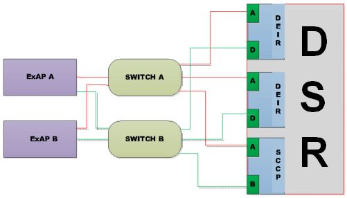
MOS is available 24 hours a day, 7 days a week, 365 days a year.

                                                                   6
What's New in This Guide
The Oracle Communications EAGLE EIR User's Guide has been updated with the
enhancement of EIR List Log Format, in Release 46.9. For more details, see EIR List
Log File.
71
Introduction
This chapter provides a brief description of the EIR feature of the Oracle
Communications EAGLE. The chapter also includes the scope, audience, and
organization of the manual; how to find related publications; and how to contact Oracle
for assistance.
Overview
This manual describes the Equipment Identity Register (EIR) feature of Oracle
Communications EAGLE. The EIR feature is used to reduce the number of GSM
mobile handset thefts by providing a mechanism to assist network operators in
preventing stolen or disallowed handsets from accessing the network. This control
is accomplished by comparing the International Mobile Equipment Identity (IMEI) that
is provided during handset registration to a set of three lists provided by the network
operator:
• Black - Mobile Stations (MS) on the Blacklist will be denied access to the network
• White - MSs on the Whitelist will be allowed access to the network
• Gray - MSs on the Graylist will be allowed on the network, but may be tracked
EIR is an optional feature on EAGLE, and can be turned on but not off after the feature
is enabled using a feature access key. EIR is mutually exclusive with LNP in the
system, unless the Dual ExAP Configuration feature is enabled.
References
Refer the following documents for EIR feature related configurations:
• Application B Card Hardware and Installation Guide
• Hardware Reference Guide
• Commands User's Guide
• Administration Guide for EPAP
Acronyms and Terminology
The following table provides information about the acronyms and the terminology used
in the document.
Table 1-1 Acronyms and Terminology
Acronym Definition
EIR Equipment Identity Register
EPAP EAGLE Application Processor Provisioning
1-1Chapter 1
Acronyms and Terminology
Table 1-1 (Cont.) Acronyms and Terminology
Acronym Definition
IMEI International Mobile Equipment Identity
IMSI International Mobile Subscriber Identity (IMSI)
MS Mobile Stations
MSISDN Mobile Station International ISDN Number
SIM Subscriber Identity Module
NPP Numbering Plan Processor
RTDB Real Time Database
1-22
Feature Description
This chapter provides a functional description of the EIR feature, including network
perspectives, assumptions and limitations, a database overview, Service Module card
provisioning and reloading, EIR user interface, and an audit overview.
Equipment Identity Register Overview
A handset theft problem exists in GSM networks in many countries. A person obtains a
legitimate subscription to a network, and then obtains a legitimate IMSI, MSISDN, and
SIM card. The person initially buys an inexpensive handset and then steals a better
handset from another subscriber. After the handset is stolen, the thief replaces the
SIM card with a legitimate SIM card. Because the SIM card and subscriber information
contained on the SIM card (IMSI, MSISDN) are legitimate, the phone will operate and
the network operator cannot determine that the subscriber is using a stolen handset.
In addition to individual handset theft, organized groups stealing entire shipments of
mobile handsets from warehouses and sell these handsets on the Black Market.
The Equipment Identity Register (EIR) is a network entity used in GSM networks that
stores lists of IMEI numbers, which correspond to physical handsets (not subscribers).
The IMEI is used to identify the actual handset, and is not dependent upon the
International Mobile Subscriber Identity (IMSI), Mobile Station International ISDN
Number (MSISDN), or the Subscriber Identity Module (SIM). The IMSI, MSISDN, and
SIM are all subscriber-specific, and move with the subscriber when purchasing a new
handset. The IMEI is handset-specific.
The EIR feature can be used to reduce the number of GSM mobile handset thefts by
providing a mechanism that allows network operators to prevent stolen or disallowed
handsets from accessing the network. This control is accomplished by comparing
the International Mobile Equipment Identity (IMEI) that is provided during handset
registration to the following set of three lists provided by the network operator:
• Black - Mobile Stations (MS) on the Blacklist are denied access to the network
• Gray - MSs on the Graylist are allowed on the network, but may be tracked
• White - MSs on the Whitelist are allowed access to the network
The EPAP Real Time Database (RTDB) stores the Whitelist, Graylist, and Blacklist of
IMEI numbers. The RTDB is downloaded to Service Module cards in EAGLE. When
a subscriber roams to a new MSC or VLR location, the handset attempts registration
with the MSC or VLR. Before the MSC registers the subscriber with the VLR, it may
send a query to the EAGLE for EIR status of the handset. EAGLE returns a response
indicating whether the IMEI is allowed, disallowed, or not valid. If the IMEI is allowed,
the MSC completes registration; otherwise, registration is rejected.
The RTDB may also contain associations between individual IMEIs and IMSIs. This
can provide a further level of screening by directly associating a particular IMEI with a
particular IMSI. This association is used in the following way:
• If an IMEI is found on a Blacklist, an additional check of the IMSI could then be
made.
2-1Chapter 2
EIR Call Flows
• If the IMSI from the handset matches the IMSI provisioned with the IMEI, this
would override the Blacklist condition, and allow registration to continue. This
could be used to protect against mistaken Blacklist entries in the database, or to
prevent unauthorized "handset sharing". This association could also be used in
other ways.
The IMSI Range Logic Support feature includes an IMSI range check logic prior to an
IMEI lookup in the database. This check prevents low ARPU users from using certain
devices, in addition to the EIR stolen handset check.
The EIR feature is mutually exclusive with LNP, unless the Dual ExAP Configuration
feature is enabled.
EIR Call Flows
When a handset roams into a new MSC/VLR area, it attempts a registration procedure
with the VLR. In a network without the EIR function, this procedure results in the VLR
sending a location update message to the HLR, providing the HLR with the current
MSC location of the Mobile Station (MS)/handset. When the EIR function is deployed
in a network, this registration procedure is interrupted in order to validate the IMEI
of the MS/handset attempting to register before completing the registration procedure
and updating the HLR.
In the network with EIR, the MSC/VLR sends a MAP_CHECK_IMEI message to the
EAGLE requesting EIR processing before sending a location update to the HLR. This
message contains, at a minimum, the IMEI of the MS attempting registration. It may
also contain the IMSI of the subscriber whose SIM card is currently being used in the
MS/handset. Upon receipt of this message, the EIR feature searches the White, Gray,
and Black Lists for a match on the IMEI. The EIR feature then returns a response to
the MSC. Depending upon the result of the search, the response contains either the
Equipment Status of the MS/handset (whether the IMEI for the MS/handset is allowed
or not, based on its status in the White, Gray, or Black Lists), or a User Error (invalid or
unknown IMEI). The MSC then either continues the registration procedure (if the IMEI
is allowed), or rejects it (if the IMEI is disallowed, invalid, or unknown).
If the IMSI is also included in the message, EIR attempts to match this IMSI to one
provisioned with the IMEI before sending a response to the MSC. A match on IMSI in
this case overrides any Black List condition found based on the IMEI match alone, and
causes a response of MS allowed.
Figure 2-1 illustrates the steps of the following EAGLE EIR call flow process.
1. The MS/handset roams into a new serving MSC/VLR area, and begins the
registration procedure with the Base Station (BS).
2. The BS begins the registration procedure with MSC/VLR.
3. Before allowing the MS/handset to register on the network, and before updating
the HLR with the new MSC information, the MSC launches a MAP_CHECK_IMEI
message to the EAGLE for EIR feature processing. This message is either MTP-
routed directly to the point code of the EAGLE and the EIR local subsystem, or is
GT-routed and the EAGLE performs global title translation on the message to its
own point code and the EIR local subsystem.
4. EIR retrieves the IMEI and/or IMSI from the message and searches the EIR
information in the RTDB for a match. See Table 2-1 and Table 2-2. This search
may result in the IMEI being on one or more of the White, Gray, or Black Lists,
or it may result in an invalid or unknown IMEI (no match). It may also result in
2-2Chapter 2
EIR Call Flows
an invalid IMSI-IMEI combination. Based on the results of the search, the EAGLE
returns a MAP_CHECK_IMEI_ack containing either the Equipment Status (IMEI
allowed or not allowed), or a User Error (invalid or unknown IMEI).
5. (Not shown). The MSC either rejects or completes the registration attempt,
depending on the information returned from EIR.
Figure 2-1 EIR Call Flow
The RTDB EIR information contains lists of IMEIs, and an indication as to the list
where they are located. There are two types of IMEIs: Individual IMEIs (Table 2-1) and
ranges of IMEIs (Table 2-2). The Individual IMEIs are searched first. The IMEI entries
in this list may also contain an association to an IMSI. If no individual IMEI match is
found, IMEI ranges are searched.
EIR can support up to 32 million individual IMEIs. A total of up to 100,000 IMEI ranges
are supported. The maximum EAGLE RTDB capacity for all EPAP service features,
including EIR, G-Flex, and G-Port, is 120 million individual numbers. Entries for these
other services (MSISDNs for G-Port or IMSIs for G-Flex), reduce the available capacity
for IMEIs. Also, if IMSIs are entered for the IMSI Check of EIR, those entries also
reduce the available IMEI capacity.
Note:
Database capacity can be expanded by using the EPAP Data Split feature
and/or the EAGLE MNP Data Base Support for 240M DN feature.
For extended database capability, refer to the 120M DN and 120M
IMSIs via Split Database feature (Part Number: 893-0398-01) in Database
Administration - GTT User's Guide.
2-3Chapter 2
EIR Call Flows
Table 2-1 Example of Individual IMEIs
IMEI IMSI (optional) White List Gray List Black List
12345678901234 49586725689412 No No Yes
5
23456789012345 No Yes No
6
49876523576823 No Yes Yes
68495868392048 49586756587423 Yes Yes No
6
29385572695759 Yes Yes Yes
As shown in Table 2-1, it is possible for a given IMEI to be on more than one list
(on the White List, and also on the Gray and/or Black List). The logic illustrated by
Table 2-2 is used to determine which answer to return in the CHECK_IMEI response,
determined by which list or lists the IMEI is on. Table 2-2 also shows three possible
EIR Response Types. The EIR Response Type is a system-wide EIR option that is
configured by the user. The combination of the setting of the EIR Response Type, the
list or lists in which the IMEI is located, and the optional IMSI check determines the
response that is returned to the querying MSC.
Table 2-2 Logic for IMEIs in Multiple Lists
Presence in List EIR Response Type
White Gray Black Type 1 Type 2 Type 3
X in White List in White List in White List
X X in Gray List in Gray List in Gray List
X X X in Black List in Black List in Black List
X X in Black List in Black list in Black List
X in Gray List in Gray List unknown
X X in Black List in Black List unknown
X in Black List in Black List unknown
in White List unknown unknown
Example Scenarios
Example 1
1. A CHECK_IMEI is received with IMEI = 49876523576823, no IMSI in message.
2. An individual IMEI match is found (Table 2-1, entry 3), indicating that the IMEI is on
the Gray and Black Lists. The EIR Response Type is set to Type 3, and an IMSI is
not present.
3. Table 2-2 indicates that the required response is Unknown.
4. EIR formulates a CHECK_IMEI error response with Error = 7
unknownEquipment.
Example 2
Example 2 is the same as Example 1, except that the setting of the EIR Response
Type is re-provisioned by the operator to Type 2.
2-4Chapter 2
EIR Call Flows
1. A CHECK_IMEI is received with IMEI = 49876523576823, no IMSI in message.
2. An individual IMEI match is found (Table 2-1, entry 3), indicating that the IMEI is on
the Gray and Black Lists. The EIR Response Type is set to Type 2, and an IMSI is
not present.
3. Table 2-2 indicates that the required response is Black listed.
4. EIR formulates a CHECK_IMEI response with Equipment Status = 1
blackListed.
Example 3
1. A CHECK_IMEI is received with IMEI = 12345678901234, and IMSI =
495867256894125.
2. An individual IMEI match is found (Table 2-1, entry 1) indicating that the IMEI is on
the Black List.
3. The EIR Response Type is set to Type 1.
4. Table 2-2 indicates that the normally required response would be Black listed,
however; because an IMSI is present in the message, and the IMEI is on the Black
List, the IMSI is compared to the IMSI entry in the database for this IMEI.
5. In this case, the IMSI in the RTDB matches the IMSI in the query, thus the Black
Listed condition is cancelled.
6. EIR formulates a CHECK_IMEI response with Equipment Status = 0
whiteListed.
Example 4
1. A CHECK_IMEI is received with IMEI = 12345678901234, and IMSI =
495867256894125.
2. An individual IMEI match is found (Table 2-1, entry 1), indicating that the IMEI is on
the Black List.
3. The EIR Response Type is set to Type 1.
4. Table 2-2 indicates that the normally required response would be Black listed,
however; because an IMSI is present in the message, and the IMEI is on the Black
List, the IMSI is compared to the IMSI entry in the RTDB for this IMEI.
5. In this case, the IMSI in the RTDB does not match the IMSI in the query, the Black
Listed condition is maintained.
6. EIR formulates a CHECK_IMEI response with Equipment Status = 1
blackListed.
EIR List Determination
If the EIR Global Response configuration option is set (with the eirgrsp parameter of
the chg-gsmopts command) to a value other than off, the IMEI is treated as being
on the list indicated by the EIR Global Response option, regardless of the actual status
of the IMEI. No list logic processing is performed on the IMEI.
If the EIR Global Response option is set to off, the individual IMEIs are searched
first. If no match is found, the range IMEIs are searched next. If the IMEI is found
only on the White List after either search, the list logic processing is complete, and the
White List status of the IMEI is sent to the MSC.
2-5Chapter 2
EIR Protocol
Black List Processing
If the IMEI is found on the Black List after either search, list logic processing continues
based on the EIR Response Type, set by the eirrsptype parameter of the chg-
gsmopts command. If the EIR Response Type is type 3, and the IMEI is not also
found on the White List, the status of the IMEI is unknown.
If the IMEI is also found on the White List, or if the EIR Response Type is either type
1 or 2, the value of the IMSI Check option, set with the eirimsichk parameter of the
chg-gsmopts command, is checked. If the IMSI check option is on, and the IMSI is
present in the message, the RTDB is searched for the IMSI. If there is a match for
the IMSI, the status of the IMEI is determined to be “White with Override.” If there is
no match for the IMSI, the status of the IMEI is determined to be “Black with IMSI
Match Failed.” If the value of the IMSI Check option is off, the status of the IMEI is
determined to be "on the Black List".
Gray List Processing
If the IMEI is found on the Gray List after either search, list logic processing continues
based on the EIR Response Type, set by the eirrsptype parameter of the chg-
gsmopts command. If the EIR Response Type is type 3, and the IMEI is not also
found on the White List, the status of the IMEI is unknown.
If the IMEI is also found on the White List, or if the EIR Response Type is either type 1
or 2, the status of the IMEI is determined to be "on the Gray List".
EIR Protocol
The EAGLE supports the EIR capability point code type and a local subsystem that
is entered into the MAP table. The EIR local subsystem has a mate subsystem, and
a concerned point code group assigned to it. ANSI, ITU-I, and ITU-N point codes are
supported in the MAP table. The EIR subsystem cannot be set to Load Shared mode
(as end nodes do not perform load sharing), but is set to Dominant or Solitary mode.
Messages for Local Subsystems
The message arrives at the EIR subsystem as Rt-on-SSN or Rt-on-GT. If the message
arrives as Rt-on-SSN, it must contain either the EAGLE true point code or the EIR
capability point code in the DPC field of the message, and EAGLE EIR subsystem
number in the Called Party Subsystem field of the message. If EIR query has the
EAGLE capability point code for the DPC, then the EAGLE processes the message,
but is not able to divert this message in the event of subsystem failure.
If a message arrives at the EIR subsystem as Rt-on-GT, it should also contain a
service selector that translates to the EIR subsystem. These messages also contain
one of EAGLE capability point codes in the DPC field. The EAGLE also processes the
message if it has the EAGLE true point code for the DPC, but it is not able to divert
these messages in the event of subsystem failure.
If the EIR local subsystem is offline and the mated subsystem is available, the Routing
Indicator is used to determine whether to reroute:
• If the message arrived Rt-on-SSN, the message is not rerouted to the mate. In
this case, EAGLE is acting as an end node, and end nodes do not reroute. If the
return on error option is set, the EAGLE generates a UDTS, otherwise it discards
the message.
2-6Chapter 2
EIR Protocol
• If the message arrived on Rt-on-GT, the message is rerouted to the mated
subsystem. In this case, the EAGLE is acting as both STP and SCP, and STPs do
reroute messages.
Multiple Local Subsystems
The EAGLE supports provisioning Capability Point Codes (CPCs) for two or more
local subsystems, allowing local subsystems for two or more EPAP-related features to
operate at the same time in the system. For example, local subsystems for the ATINP
feature and the EIR feature can coexist in the system.
Though queries meant for any local system are still be processed if they are sent
with DPC = STP CPC, it is strongly recommended not to use the STP CPC for such
queries. Instead, the CPC for the appropriate subsystem should be used as the DPC
of the message. For instance, for LNP queries use the LNP CPC, not the STP CPC;
for EIR queries, use the EIR CPC, and so on.
MTP and SCCP Management to Support EIR
If the EIR local subsystem is offline, the EAGLE sends SSPs that cause the Rt-on-
SSN message to be diverted to the mate subsystem. These do not cause the Rt-on-
GT messages to be diverted. In order to make other nodes divert Rt-on-GT traffic to
the mate, the EAGLE sends response method TFPs to the OPC of the message, when
messages arrive Rt-on-GT for one of the EIR Capability Point Codes and the result
of translation is the EAGLE EIR subsystem. This TFP should cause the OPC to divert
traffic to the mate. If a message arrives Rt-on-GT for the EAGLE True Point Code, the
EAGLE does not generate a TFP. Therefore, nodes that send Rt-on-GT traffic to the
EAGLE should use an EIR Capability Point Code, not the EAGLE True Point Code.
If the EAGLE receives an RSP (Route Set Test Message - Prohibited) for an EIR
Capability Point Code, and the EIR subsystem is offline, the EAGLE does not reply.
If the EAGLE receives an RSR (Route Set Test Message - Restricted) for an EIR
Capability Point Code, and the EIR subsystem is offline, the EAGLE replies with a
TFP concerning the Capability Point Code. When the EIR subsystem is online, RSRT
replies to both RSRs and RSPs for an EIR Capability Point Code with a TFA.
Check_IMEI Message Handling
When the CHECK_IMEI message is received by protocol, the, IMSI (if active) and
SVN are parsed from the MSU. Because different vendors place the IMSI information
in different locations within the message, the decoder searches for the IMSI in multiple
locations.
Once the required data is parsed, a lookup is performed in the RTDB to determine the
response type for the IMEI/IMSI combination.
The appropriate response message is sent to the originating MSC.
Encoding Errors
When a Response is generated, it is sent based on the CgPA information in
the incoming message. However, some conditions may prevent the EAGLE from
generating the response. Most of the errors involve GTT on the CgPA; if the incoming
data is Rt-on-SSN, the number of potential errors is much smaller.
Whenever an encoding error is detected, the Response message is discarded.
2-7Chapter 2
EIR List Log File
Data Collection
See EIR Measurements for a description of the measurements collected for the EIR
feature.
The rept-stat-sccp command output displays EIR subsystem status, EIR
summary and card statistics, and CPU usage related to EIR. See rept-stat-sccp.
EIR List Log File
The EIR feature allows for detection and logging of subscribers using handsets that
have been White Listed, Black Listed, or Grey Listed by a service provider. These
messages are generated by the EAGLE and forwarded to the MPS platform for later
retrieval. Messages may be forwarded from any of the provisioned Service Module
cards. Messages are received and logged independently by both MPS servers.
The files are located in the/var/TKLC/epap/free filesystem and named as follows:
eirlog_hostname.csv
Where:
hostname = the hostname of the MPS server that recorded the log.
Each entry in the EIR log file contains information about the caller and handset, a
timestamp documenting the time the server received the log entry, and a unique
identifier used for comparison with the mate server. See EIR List Log Format for more
information about the format of the file and the fields within the file.
The log file is available via Secure FTP using the appuser user.
The EIR log file contains the last 2 million entries received from the EAGLE. This file
may be deleted through the EPAP GUI Manage Files & Backups screen.
EIR Log File Serviceability
The file system used by EIR Log Files is approximately 35 GB in size and is used for
all of the following in addition to storing EIR log files:
• UI Configuration database backup
• Provisioning database backup
• Real-time database backup
• System log file captures
When the file system reaches 80% of it's total capacity a minor alarm is raised. A
major alarm is raised at 90%. All of the files in this partition are managed from the
Debug->Manage Logs & Backups screen on the GUI.
EIR Log entries are delivered to and stored on the MPS using a "best effort" approach.
The following three major factors impact the successful delivery of a log entry:
• Service Module card connectivity: Service Module cards have a limited buffer for
storage of EIR log entries. If the data cannot be delivered, it is discarded.
• UDP Broadcast: A Service Module card broadcasts a log entry to both MPS
servers. Although experience shows this broadcast method on a private network to
be highly reliable, it is not guaranteed.
2-8Chapter 2
EIR List Log File
• MPS server availability: If an MPS server is down or unreachable, log entries are
not collected and stored. Hourly log entries may be later compared with those
collected on the mate MPS server using the entry's unique identifier.
EIR List Log Format
The export IMEI Black List hits file consists of CSV entries separated by newlines.
Each entry contains the following fields:
• Time/Date stamp: This field represents the time at which the MPS server received
the entry from the Service Module card. The time is generated by the MPS using
the configured system time. It is formatted as yyyyMMddhhmmss (year, month,
day, hour, minute, second).
• Source Identifier: This field is an IP address that uniquely identifies the Service
Module card that sent the log entry. This field can be used in combination with the
Source Sequence Number to correlate log entries with those on the mate MPS
server.
• Source Sequence Number: This field is an integer that uniquely identifies the entry
per source Service Module card. This field can be used in combination with the
Source Identifier to correlate log entries with those on the mate MPS server.
• IMSI: International Mobile Subscriber Identity for this entry
• IMEI: International Mobile Equipment Identity for this entry
• Response Code: These response codes are possible (2 and 4 are invalid values):
– 0: Indicates that the IMEI is Black Listed.
– 1: Indicates that the IMEI is Gray Listed.
– 2: Indicates that the IMEI is White Listed.
– 3: Indicates that the IMEI was Black Listed, but the IMSIs matched resulting in
a White List Override.
– 5: Indicates that the IMEI was Black Listed and the IMSIs did not match
resulting in Black List Continues.
– 6: Indicates that the IMEI was not Black/Gray/White Listed, resulting in White
List.
• Point Code Type: Point code type of the message originator. Following point code
types are possible:
– Host: indicates the origin-host
– ANSI: indicates ANSI point code
– ITUI: indicates ITU International point code
– ITUN: indicates a 14-bit ITU National point code
• Point Code or Hostname: Point code of the message originator (OPC) or
hostname present in the origin-host of the diameter message.
For example, If an MPS server receives entry id 1234 on July 15, 2003, at exactly
4:36 PM from a Service Module card provisioned at address 192.168.120.1 indicating
that Black Listed subscriber 9195551212 using handset 12345678901234 has been
2-9Chapter 2
Additional EIR Data Files
detected and the originator of the message is from the ANSI point code 3-3-1, the
following log entry is created:
20030715163600,192.168.61.1,1234,9195551212,12345678901234,0,ANSI,3-3-1
Additional EIR Data Files
This feature makes significant use of the /var/TKLC/epap/free file system. The
following files may be present:
Table 2-3 Additional Files
Data Type Size Creation Cleanup
UI Configuration < 1K each On demand at Manual
database backup upgrade
Provisioning database Up to 12 GB each On demand at Manual
backup depending on the upgrade
amount of customer
data and the size of
the transaction logs
Real-time database 4 GB each On demand at Manual
backup upgrade
System log file 5-20 MB or more On demand by Manual
captures depending on core customer service
files, and overall life of
system.
EIR Export Depends on the Manual by customer Manual
amount of customer
data. Less than
100MB per million
instances
EIR Auto Export (new Depends on the Scheduled by Automatic after
for EIR) amount of customer customer transferred to
data. Less than customer
100MB per million
instances
PDBI Import Determined by Manual (FSTP) Manual
customer need
PDBI Auto Import Determined by Manual (FSTP) Automatic after data
(new for EIR) customer need imported
PDBI Auto Import If no errors, very Automatic Automatic after
results (new for EIR) small. May be up to transferred to
double the PDBI Auto customer
Import file size worst
case
EIR blacklist logs (new Assuming no more Automatic Automatic. There
for EIR) than 360,000 updates should be
per hour from the approximately 25 logs
EAGLE, each file is no at most.
more than 25MB
2-10Chapter 2
EIR S13/S13' Interface Support (Diameter EIR/DEIR)
EIR S13/S13' Interface Support (Diameter EIR/DEIR)
Equipment Identity Register (EIR) is a database containing records of all mobile
stations that are allowed or banned in a network. Generally, the banned mobile
stations have been declared lost or stolen. Each mobile station is identified by its
International Mobile Equipment Identity (IMEI). When a mobile station is detected
by the network, the Mobility Management Entity (MME) or Serving GPRS Support
Node (SGSN) requests the IMEI of the mobile station, which is sent to the EIR for
authorization.
The EIR S13/S13' Interface Support feature allows EIR to support the S13 and
S13' Diameter interfaces for these messages. By supporting the S13/S13' interfaces,
Diameter requests can be received by an EAGLE card and processed by EIR, and
then a response transmitted back to the requester.
EIR S13/S13' Interface Support Limitations
• An E5-SM8G-B or SLIC card running DEIR64 GPL (S13 card) is required to
support the EIR S13/S13' Interface Support feature.
• If the S13 card loses EPAP connection, the cable of the S13 card must be
manually moved to the other EPAP and the S13 card must be reprovisioned with
the address of the new EPAP.
• An S13 card can process traffic using a stale database.
• If the Signaling network interface on an S13 card goes down, the S13 traffic
corresponding to that interface is affected.
• An external load balancer is needed to support load-balancing of Diameter
messages.
• Relay and proxy modes are not included.
• The response is returned on the same Diameter connection on which the request
was received.
• The EIR S13/S13' Interface Support feature does not support E5-MS or FTRA for
the new commands associated with the EIR S13/S13' Interface Support feature
(Diameter EIR/DEIR).
• Maximum diameter message length supported by current EIR S13/S13's Interface
implementation is 448 bytes.
EIR S13 Connection States
S13 Diameter connections maintain a state machine on the S13 Card. The states in
Table 2-4 are maintained for each diameter connection.
Table 2-4 S13 State
State Description
CLOSED SCTP association is set to OPEN=NO and
SCTP socket is closed.
INACTIVE SCTP connection is not established. Initial
state
2-11Chapter 2
EIR S13/S13' Interface Support (Diameter EIR/DEIR)
Table 2-4 (Cont.) S13 State
State Description
OPEN SCTP Connection is established. Ready to
accept Capability Exchange Request
ACTIVE Ready to process ECR messages
CLOSING Transit state to process outstanding messages
before moving to Inactive state
PENDING Waiting for remote to send DWA
An event on the S13 diameter connection causes the transitions between these states.
Table 2-5 depicts the events that cause a state transition and action taken on a
particular event.
The S13 Diameter connection is CLOSED initially when OPEN is set to NO for the
associated SCTP connection. When OPEN is changed to YES using the chg-assoc
command, the Diameter connection is set to INACTIVE state, and attempts to change
the SCTP connection status to UP by exchanging SCTP related messages (INIT/INIT-
ACK). When the SCTP connection is established, the Diameter connection moves
to the OPEN state and waits for a CER message from the peer. If an Invalid CER
or any message other than CER is received in the OPEN state, the message is
discarded and the SCTP connection is closed by sending an abort to the peer. If
a Valid CER is received in the OPEN state, a CEA response is formatted per the
connection configuration and is sent to the peer. The Diameter connection moves to
the ACTIVE state and is able to receive and process ECR messages. If the SCTP
connection is locally closed (by changing OPEN=NO), the corresponding Diameter
connection sends a DPR to the peer and waits for an Acknowledgement (DPA) from
the peer, and the Td timer is started. The SCTP connection continues to process the
outstanding messages on the Diameter connection until the DPA message is received
or the Td timer expires. In both cases, the Diameter connection and SCTP connection
are closed. If the diameter connection is in the INACTIVE state or the OPEN state,
manually closing the local connection moves the state back to CLOSED.
Table 2-5 S13 Event and State Transition Table
Current State Event Action New State
Any State Transport Connection Stop Any running INACTIVE
disconnected timer
INACTIVE Receive Any message Discard Message INACTIVE
INACTIVE Transport Connection None OPEN
established
INACTIVE Manually Close Local None CLOSED
Connection
OPEN Invalid CER Send CEA with Error INACTIVE
Cause Disconnect
Transport
OPEN Any Message other Silently Discard INACTIVE
than CER Message Disconnect
Transport
OPEN Valid CER Send CEA with ACTIVE
SUCCESS Start Tw
timer
2-12Chapter 2
EIR S13/S13' Interface Support (Diameter EIR/DEIR)
Table 2-5 (Cont.) S13 Event and State Transition Table
Current State Event Action New State
OPEN Manually Close Local None CLOSED
Connection
ACTIVE ECR message Send ECA Restart Tw ACTIVE
timer
ACTIVE DWR message Send DWA Restart Tw ACTIVE
timer
ACTIVE Any message other Discard Message and ACTIVE
than ECR / DWR / send error response
DWA / DPR
ACTIVE CER message Silently discard ACTIVE
message
ACTIVE Invalid DPR message Send DPA with Error ACTIVE
Cause
ACTIVE Valid DPR message Send DPA Stop INACTIVE
all timers Disconnect
Transport
ACTIVE Tw timer Expiry #1 Send DWR Restart Tw ACTIVE
timer
ACTIVE Tw timer Expiry #2 Send DWR Restart Tw PENDING
timer
ACTIVE Manually Close Local Send DPR Stop Tw CLOSING
Connection timer Start Td timer
CLOSING ECR message Send ECA message CLOSING
CLOSING DPA message Disconnect Transport INACTIVE
CLOSING DPR message Disconnect Transport INACTIVE
CLOSING None Wait for Td Disconnect CLOSED
Transport
PENDING DWA Message Restart Tw Timer ACTIVE
PENDING ECR Message Send ECA Restart Tw ACTIVE
Timer
PENDING Tw timer Expiry #3 Send DPR Stop Tw CLOSING
timer Start Td timer
PENDING DPR Message Send DPA Stop INACTIVE
all timers Disconnect
Transport
PENDING Manually Close Local Send DPR CLOSING
Connection Stop Tw timer
Start Td timer
S13 Supported Messages
Diameter messages are classified as requests or responses. The Diameter request
and response messages in Table 2-6 are processed by the EAGLE. The S13 card
processes only these messages and sends a 3001 response for all unsupported
Diameter request messages.
2-13Chapter 2
EIR S13/S13' Interface Support (Diameter EIR/DEIR)
Table 2-6 S13 Messages supported by EAGLE
Message Name Short Name Command Code EAGLE Description
Behavior
Capability CER 257 Receive Exchanged
Exchange between peers to
Request discover the
Capability CEA 257 Send identity and
Exchange capabilities of the
Answer peer.
Disconnect-Peer- DPR 282 Recv/Send - Both These messages
Request are exchanged
Disconnect-Peer- DPA 282 Recv/Send - Both between peers
Answer when they agree
to disconnect the
transport layer
connection.
Device- DWR 280 Recv/Send - Both These messages
Watchdog- check the status
Request of connection
Device- DWA 280 Recv/Send - Both between two
Watchdog- peers when no
Answer traffic has been
exchanged
between them.
ME-Identity- ECR 324 Receive These messages
Check-Request are exchanged on
ME-Identity- ECA 324 Send S13/S13'
Check-Answer interface between
MME/SGSN and
EIR database to
track the lost/
stolen handset.
S13 Supported AVPs
The Diameter Attribute Value Pairs (AVPs) supported on the S13 card are shown in
Table 2-7.
Table 2-7 AVPs Supported by S13
AVP Name AVP Code Description
AUTH-APPLICATION-ID 258 This AVP contains the list of
application IDs supported. The
value of the Auth-Application-
Id AVP in ECR/ECA must
match the Application Id
present in the Diameter
message header.
2-14Chapter 2
EIR S13/S13' Interface Support (Diameter EIR/DEIR)
Table 2-7 (Cont.) AVPs Supported by S13
AVP Name AVP Code Description
AUTH_SESSION_STATE 277 This AVP is present in the
ECR message and specifies
whether the state for a
particular session is to be
maintained. These values are
supported:
• STATE_MAINTAINED 0
• NO_STATE_MAINTAINED
1
DESTINATION_REALM 283 This AVP contains the Realm
to which the message is to be
routed. This is a mandatory
AVP in an ECR message. The
value is checked against the
local Realm value configured
in the IPHOST table.
DISCONNECT_CAUSE 273 This AVP is included in a DPR
request message to inform
the peer of the reason for
its intention to shut down the
transport connection. It is of
type Enum and supports these
values:
• Rebooting - 0
• Busy - 1
• Do_not_want_to_talk_to_
you - 2
Disconnect cause to be
specified in outgoing DPR
message is configured in
DEIROPTS table.
EQUIPMENT_STATUS 1445 This mandatory AVP in the
ECA message contains the
status of equipment after
performing EIR database
lookup (Blacklist, Whitelist,
Greylist, or Unknown).
ERROR-MESSAGE 281 The Error message AVP
contains the human readable
text of error result code to be
sent to the peer.
FAILED_AVP 279 This is a grouped AVP
and provides the debugging
information when a request is
rejected or not fully processes
due to erroneous information
in a specified AVP.
HOST_IP_ADDRESS 257 This AVP contains IP
addresses of the originator of
the Diameter message.
Note: Only one instance of
this AVP is supported. All
other instances are discarded.
2-15Chapter 2
EIR S13/S13' Interface Support (Diameter EIR/DEIR)
Table 2-7 (Cont.) AVPs Supported by S13
AVP Name AVP Code Description
IMEI 1402 This AVP contains the IMEI of
the specific equipment.
ORIGIN_HOST 264 The Origin Host AVP contains
the hostname of the originator
of the Diameter message. The
value is checked against the
remote host value configured
in the IPHOST table.
ORIGIN_REALM 296 This AVP contains the Realm
of the originator of the
Diameter message. The value
is checked against the remote
Realm value configured in the
IPHOST table.
PRODUCT_NAME 269 This AVP contains the vendor
assigned name of the product.
Product Name to be specified
in outgoing message is
configured in DEIROPTS
table.
Note: This is a mandatory
AVP in CER.
PROXY-INFO 284 If any Proxy-Info AVP is
present in the request, it is
added to the answer message
in the same order as it is
present in the request.
ROUTE-RECORD 282 If this AVP is present in the
request, it is added to the
answer message in the same
order as it is present in the
request.
RESULT_CODE 268 This AVP indicates whether
a particular request was
completed successfully or an
error occurred.
SESSION-ID 263 If this AVP is present in
the request message, copy
the same session ID in the
response message.
TERMINAL_INFORMATION 1401 The mandatory grouped AVP
of the ECR message contains
IMEI and software version.
The IMEI AVP value is used
for EIR database lookup.
USER_NAME 1 This AVP contains the IMSI
of the specific equipment. The
IMSI value along with IMEI is
used for database lookup.
2-16Chapter 2
EIR S13/S13' Interface Support (Diameter EIR/DEIR)
Table 2-7 (Cont.) AVPs Supported by S13
AVP Name AVP Code Description
VENDOR_ID 266 This AVP contains the
predefined IANA value
assigned to the Diameter
Software vendor. For CEA
message outgoing from
EAGLE, this parameter is set
to 0.
VENDOR_SPECIFIC_APPLIC 260 This grouped AVP in the
ATION_ID CEA message contains these
AVPs:
• vendor-id avp - Vendor Id
to be specified in outgoing
message is 10415.
• auth-application-id - auth-
application-id to be
specified in outgoing
message is configured
in DEIROPTS table as
APPLID.
EIR S13/S13' Interface Support - ECA Message Encoding
After the Equipment status is determined, the ECA message with the following details
is send to the originator of the request.
• Common information
• Session-ID, Route-record or Proxy-Info AVP: If the Session-ID, Route-record or
Proxy-Info AVP is present in the ECR message, they are appended in the same
order as presented in the request message. A maximum of ten Route-record and
Proxy-Info AVPs can be copied from the request message.
• Result-Code and Equipment-Status AVPs: Result-Code and Equipment-Status
AVPs are populated as shown in Table 2-8.
Table 2-8 Mapping of EIR database Response and ECR Result
ME-Check-Identity Response
EIR Response Result Code Equipment-Staus
in Whitelist DIAMETER_SUCCESS WHITELISTED (0)
in Blacklist DIAMETER_SUCCESS BLACKLISTED (1)
in Graylist DIAMETER_SUCCESS GREYLISTED (2)
Unknown* DIAMETER_ERROR_EQUIP NA
MENT_UNKNOWN
2-17Chapter 2
DEIR on SLIC Network Redundancy Enhancement
EIR S13/S13' Interface Support Result Codes
Table 2-9 Supported Result Codes
Error-Message AVP Values
Result Code
Value Readable Value Text String
2001 DIAMETER_SUCCESS diameter success
3001 DIAMETER_COMMAND_ diameter Command not supported
UNSUPPORTED
3004 DIAMETER_TOO_BUSY diameter is busy
3007 DIAMETER_APPLICATIO diameter application not supported.
N_UNSUPPORTED Note: Only EIR Application ID is supported.
3008 DIAMETER_INVALID_HD invalid bits in diameter header
R_BITS
3010 DIAMETER_UNKNOWN_ unknown peer
PEER
5001 DIAMETER_AVP_UNSUP diameter avp not supported
PORTED
2001 DIAMETER_SUCCESS diameter success
3001 DIAMETER_COMMAND_ diameter Command not supported
UNSUPPORTED
3004 DIAMETER_TOO_BUSY diameter is busy
3007 DIAMETER_APPLICATIO diameter application not supported.
N_UNSUPPORTED Note: Only EIR Application ID is supported.
5004 DIAMETER_INVALID_AVP invalid avp value
_VALUE Note: Received invalid IMEI or IMSI value .
5005 DIAMETER_MISSING_AV missing avp
P
5006 DIAMETER_RESOURCES Diameter Resource Exceeded
_EXCEEDED
5009 DIAMETER_AVP_OCCUR diameter avp occurs too many times
S_TOO_MANY_TIMES
5010 DIAMETER_NO_COMMO no common application
N_APPLICATION
5011 DIAMETER_UNSUPPORT diameter version not supported
ED_VERSION
5014 DIAMETER_INVALID_AVP invalid avp length
_LENGTH
5015 DIAMETER_INVALID_ME invalid message length
SSAGE_LENGTH
5422 DIAMETER_ERROR_EQU unknown equipment
IPMENT_UNKNOWN
DEIR on SLIC Network Redundancy Enhancement
Before the DEIR on SLIC Network Redundancy Enhancement, the Diameter EIR
(DEIR) application architecture used a single network connection to the EPAP and a
single connection to the signaling network, as shown in Figure 2-2.
2-18Chapter 2
DEIR on SLIC Network Redundancy Enhancement
Figure 2-2 DEIR Network Connectivity without SLIC Card
The DEIR on SLIC Network Redundancy Enhancement introduces network
communication redundancy.
Overview
With the DEIR on SLIC Network Redundancy Enhancement, four network interfaces
are supported; two interfaces for EPAP communication and two interfaces for
signaling. One SLIC card with the DEIR application can connect to two EPAP and
two signaling networks at the same time. As shown in Figure 2-3, interfaces A and
D are used for EPAP connectivity and interfaces B and C are used for the signaling
networks.
Figure 2-3 SLIC Card Network Redundancy Model
2-19Chapter 2
DEIR on SLIC Network Redundancy Enhancement
Private Network Redundancy
To support private network redundancy, the SLIC card running the DEIR application
connects to EPAP using ports A and D, as shown in Figure 2-4.
Figure 2-4 SLIC Card Private Network Redundancy
The RTDB data is downloaded in the same manner as it is done on SM8G-B cards,
through either the A switch or the B switch. However, with SLIC cards, upon failure of
one switch or port (for example, switch A or a SLIC card's A port), all SLIC cards can
be switched to receive data over the other switch and port (for example, Switch B and
SLIC port D).
Signaling Network Redundancy
To support signaling network redundancy, a SLIC card with the DEIR application
connects to signaling networks using interfaces B and C, as shown in Figure 2-5.
Figure 2-5 SLIC Card Signaling Network Redundancy
If one interface/switch goes down, traffic switches to another port/switch, as the SLIC
card running the DEIR application supports multi-homing (see Multi-Homing Support).
2-20Chapter 2
Hardware Requirements
Multi-Homing Support
SCTP multi-homing provides a level of fault tolerance against network failures by
using alternate paths through the IP network between two endpoints, as shown in
Figure 2-6.
By enabling the redundant port in this feature, the SCTP protocol now provides SCTP
multi-homing endpoint support; that is, when an SCTP association is formed it lists
both the IP addresses for the respective interfaces (B and C). As a multi-homed
association endpoint, SCTP data is allowed to flow on either of the Ethernet interfaces
and thus provides more robust network connectivity.
Figure 2-6 Multi-Homed SCTP Association
DEIR supports SCTP IETF multi-homed server associations using both interfaces B
and C on a SLIC card. The presence of an assigned local host (lhost) and an
alternate local host (alhost) indicates that an association is multi-homed and capable
of utilizing both Ethernet interfaces for association operations.
The lhost parameter of the ent-assoc and chg-assoc commands is used to
represent the IP address that corresponds to either the B or C port of the SCTP
association end point. Multi-homed endpoints are SCTP associations configured with
both the lhost and alhost parameters. In this case, the lhost represents an IP
address corresponding to one interface (B or C) while the alhost represents an IP
address corresponding to the other interface of the same end point.
Hardware Requirements
EPAP-related features that perform an RTDB lookup require Service Module cards
(E5-SM8G-B or SLIC cards) running the SCCPHC application (for MAP-based EIR)
or E5-SM8G-B/SLIC cards running the DEIR64 application (for Diameter-based EIR).
The EAGLE can be equipped with up to 32 (31+1) Service Module cards.
Features that do not perform an RTDB lookup require Service Module cards only for
GTT processing that might be performed for the feature. These features can coexist in
systems with EPAP, but do not require an EPAP connection.
Front Panel LED Operation
On the E5-SM8G-B card, Ethernet Interface A is used for EPAP/ELAP (ExAP)
connectivity and Ethernet Interface B is used for the Signaling Network. Table 2-10
2-21Chapter 2
Hardware Requirements
and Table 2-11 describe LED operations for the Ethernet Interfaces on E5-SM8G-B
cards.
Table 2-10 E5-SM8G-B Faceplate IP Interface/Logical Link Status LED
Operation for Port A
ExAP Connection
ExAP Connection PORT A LED ACT A LED
IP Interface Status Status
IP port not configured N/A Off Off
Card inhibited
Cable removed and/or N/A Red Red
not synched
Sync and/or act- IP connection down Green (100 Mbps) / Red
ip-lnk Amber (1 Gbps)
IP connection up Green (100 Mbps) / Green
Amber (1 Gbps)
dact-ip-lnk N/A Green Red
Table 2-11 E5-SM8G-B Faceplate IP Interface/Logical Link Status LED
Operation for Port B
Signaling Connection
Link/Connection PORT B LED ACT B LED
IP Interface Status Status
IP port not configured N/A Off Off
Card inhibited
Cable removed and/or N/A Red Red
not synched
Sync Not configured Green Red
Sync and/or act- All are OOS-MT- Green Red
ip-lnk DISABLED or OOS-
MT
At least one Green Red
connection is down
(OOS-MT-DISABLED
or OOS-MT)
All configured Green Green
connections are Active
dact-ip-lnk N/A Green Red
With the SLIC card, the port A and D Ethernet interfaces are used for ExAP
connectivity and the port B and C Ethernet interfaces are used for the signaling
network.
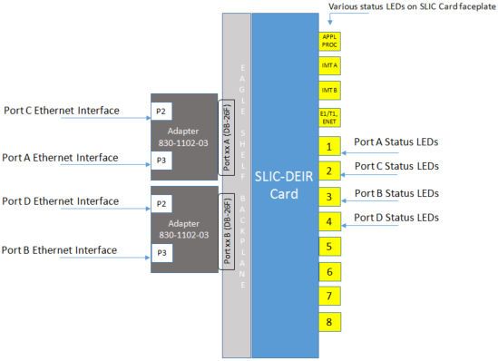
As shown in Figure 2-7, backplane DB26 ports A and B are labeled on the backplane
for each slot of the shelf (that is, Port A and Port B).
Backplane adaptors (part number 830-1102-03) are attached to backplane ports A and
B. The adaptor connected to backplane port A supports the port A Ethernet interface
through adaptor port P3, and the port C Ethernet interface through adaptor port P2.
Similarly, the adaptor connected to backplane port B supports the port B Ethernet
2-22Chapter 2
Hardware Requirements
interface through adaptor port P3, and the port D Ethernet interface through adaptor
port P2.
Figure 2-7 SLIC DEIR Card - Ethernet Interface Connections and Status LEDs
Figure 2-7 also shows the status LEDs 1 through 4 that are on the SLIC faceplate, and
their associations with the various Ethernet Interface ports. The status LEDs on the
SLIC faceplate are pictured in Figure 2-8.
2-23Chapter 2
Hardware Requirements
Figure 2-8 SLIC Faceplate Status LEDs
Table 2-12 and Table 2-13 describe LED operations for the Ethernet Interfaces on
SLIC cards.
Table 2-12 SLIC Faceplate IP Interface/Logical Link Status LED Operation for
Port A and D (Represented by LEDs 1 and 4 Respectively)
ExAP Connection
ExAP Connection PORT LED LINK LED
IP Interface Status Status
IP port not configured N/A Off Off
Card inhibited
2-24Chapter 2
MPS/EPAP Platform
Table 2-12 (Cont.) SLIC Faceplate IP Interface/Logical Link Status LED
Operation for Port A and D (Represented by LEDs 1 and 4 Respectively)
ExAP Connection
ExAP Connection PORT LED LINK LED
IP Interface Status Status
Cable removed and/or N/A Red Red
not synched
Sync and/or act-ip-lnk IP connection down Green (100 Mbps) / Red
Amber (1 Gbps)
IP connection up Green (100 Mbps) / Green
Amber (1 Gbps)
dact-ip-lnk N/A Green Red
Table 2-13 SLIC Faceplate IP Interface/Logical Link Status LED Operation for
Port B and C (Represented by LEDs 3 and 2 Respectively)
Signaling Connection
Link/Connection PORT LED LINK LED
IP Interface Status Status
IP port not configured N/A Off Off
Card inhibited
Cable removed and/or N/A Red Red
not synched
Sync Not configured Green Red
Sync and/or act-ip-lnk All are OOS-MT- Green Red
DISABLED or OOS-
MT
At least one Green Red
connection is down
(OOS-MT-DISABLED
or OOS-MT)
All configured Green Green
connections are Active
dact-ip-lnk N/A Green Red
MPS/EPAP Platform
Oracle provides the Multi-Purpose Server (MPS) platform as a subsystem of the
Oracle Communications EAGLE. The MPS provides support for EPAP-related features
that perform Real Time Database (RTDB) lookups.
The MPS is composed of hardware and software components that interact to create a
secure and reliable platform. For details about the MPS hardware, refer to Application
B Card Hardware and Installation Guide. The MPS provides the means of connecting
the customer provisioning application with the EAGLE and accepts the customer
number portability data, while accommodating numbers of varying lengths.
The Oracle Communications EAGLE Application Processor (EPAP) is software
that runs on the MPS hardware platform. EPAP collects and organizes customer
2-25You can also read