Application for controlling PICkit multipro-grammers - Janne Partanen Bachelor's thesis Bachelor of Engineering Information Technology/Game ...
←
→
Page content transcription
If your browser does not render page correctly, please read the page content below
.

                      Janne Partanen

    Application for controlling PICkit multipro-
                     grammers

                      Bachelor’s thesis

                  Bachelor of Engineering

          Information Technology/Game Programming

                         June 2020
Tekijä/Tekijät                             Tutkintonimike          Aika

Janne Partanen                             Insinööri (AMK)         Kesäkuu 2020
Opinnäytetyön nimi
                                                                   46 sivua
Ohjelma PICkit-moniohjelmoijien hallintaan                         15 liitesivua

Toimeksiantaja

Produal Oy
Ohjaaja

Teemu Saarelainen
Tiivistelmä

Tämän opinnäytetyön tavoitteena oli kehittää ja ottaa käyttöön ensimmäinen toimiva versio
ohjelmasta, joka ohjaa PICkit-moniohjelmoijia käyttämällä hyväkseen Microchipin kehittä-
mää komentorivi-käyttölittymää. Ohjelmaan luotiin lisäksi graafinen käyttöliittymä ja ohjelma
ohjelmoitin Pythonilla. Opinnäytetyön toimeksiantajana toimi Produal Oy ja ohjelman kehi-
tys tapahtui joulukuusta 2019 maaliskuuhun 2020. Produal Oy on yritys, jonka erikoisuu-
tena on rakennuksissa olevien muuttujien, kuten hiilidioksidia tai lämpötilaa mittaavien tuot-
teiden luonti. Nämä tuotteet ohjaavat rakennusautomaation niihin liittyviä osia.

Opinnäytetyön tarkoituksena on tarjota tietoa ohjelman kehitysprosessista ja ominaisuuk-
sista. Ohjelma tarjoaa Produalin tuotantotyöntekijöille tavan hallita yrityksen moniohjelmoi-
jia mahdollisimman vähällä käyttäjäsyötteellä ja antaa moniohjelmoijille joustavuutta, joka
sallii niiden käytön kaikille Produalin tuotteille. Opinnäytetyö kuvaa myös yleiset ohjelmisto-
tuotannon periaatteet, joita käytetään ohjelmistoa luotaessa, ja kuinka niitä käytetiin opin-
näytetyöohjelman luonnissa.

Opinnäytetyö saatiin valmiiksi Produalin vaatimusten mukaisesti. Kaikki Produalin kanssa
sovitut ominaisuudet toteutettiin ohjelmaan ja Produalin tuotantotiimi on ottannut ohjelman
käyttöönsä.

Opinnäytetyön litteet ovat salassapidettäviä.
Asiasanat

Python, PICkit, ohjelma, graafinen käyttöliittymä, työpöytä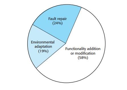
Author (authors)                             Degree                  Time

Janne Partanen                               Bachelor of Engineer- June 2020
                                             ing

Thesis title
                                                                    46 pages
Application for controlling PICkit multiprogrammers                 15 pages of appendices
Commissioned by

Produal Ltd.
Supervisor

Teemu Saarelainen
Abstract

The objective of this thesis was to develop and deploy the first operational version of an ap-
plication that can control PICkit multiprogrammers by using Microchip’s own command line
interface. A graphical user interface was created for the application and the programming
was done with Python. The thesis was commissioned by Produal Ltd, and the development
process of the application took place from December 2019 to March 2020. Produal Ltd is a
company that specializes in the creation of products that measure variables in buildings,
such as CO2 and temperature and control the related parts of building automation.

This thesis provides insight into the development process and features of the application.
The application provides Produal’s production employees with a way to control the com-
pany’s multiprogrammers with minimal user input and flexibility that allows the multipro-
grammers to be used for all of Produal’s products. This thesis also describes, in general,
software engineering practices used when creating an application and more specifically the
practices used in the creation of the commissioner’s application.

The application was finished according to the specifications that were made in cooperation
with Produal. All the features that were agreed upon with Produal were implemented into
the application, and the application has been taken into use by Produal’s production team.

The appendices of the thesis are confidential.

Keywords

Python, PICkit, application, GUI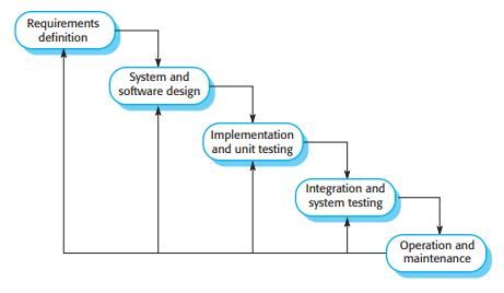
Table of Contents

TERMS AND ABBREVIATIONS ....................................................................................................................... 6

1       INTRODUCTION ............................................................................................................................................. 8

2       SOFTWARE ENGINEERING PRACTICES ....................................................................................... 9

    2.1        Requirements specification .............................................................................................................. 11

    2.2        Design ......................................................................................................................................................... 17

    2.3        Implementation ....................................................................................................................................... 21

    2.4        Testing ........................................................................................................................................................ 23

    2.5        Deployment and maintenance ........................................................................................................ 25

    2.6        Use of software engineering principles in the commissioner’s application................ 27

3       TOOLS AND TECHNOLOGIES ............................................................................................................. 28

    3.1        PICkit debuggers and programmers ............................................................................................ 29

    3.2        MPLAB X IDE, IPE and IPECMD .................................................................................................. 29

    3.3        Python ......................................................................................................................................................... 29

    3.4        Kivy............................................................................................................................................................... 30

4       IMPLEMENTATION ..................................................................................................................................... 31

    4.1        The GUI (Graphical User Interface) ............................................................................................. 31

    4.2        Programming a Produal product and programming PICkit ............................................... 35

    4.3        Adding a new product.......................................................................................................................... 39

5       TESTING AND DEPLOYMENT ............................................................................................................. 40

6       FUTURE IMPROVEMENTS .................................................................................................................... 41

7       CONCLUSION ................................................................................................................................................ 42

REFERENCES ........................................................................................................................................................ 43

LIST OF FIGURES................................................................................................................................................. 46

LIST OF LISTINGS ................................................................................................................................................ 46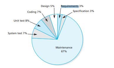
APPENDICES

             APPENDIX 1. PICKIT MULTIPROGRAMMER USER MANUAL ...................
             APPENDIX 2. SOURCE CODE .....................................................................
6

TERMS AND ABBREVIATIONS

ATM                       Automatic Teller Machine. A machine
                          that can be used to retrieve physical
                          money.

CNL                       Current Number in Loop. Refers to the
                          current number in the loop that creates
                          subprocesses from 1 to the chosen num-
                          ber of PICkits.
FURPS+                    An abbreviation that means: Functional-
                          ity, Usability, Reliability, Performance,
                          Supportability. Refers to non-functional
                          system properties. Marsic (2012, 75.)
GUI                       Graphical User Interface. An interface
                          that directs the software through an inter-
                          active interface where selections are
                          made using a mouse (Bell 2005, 54-55)

HEX files                 Files that contain data in a hexadecimal
                          format typically used by programmable
                          logic devices, such as microcontrollers.
IDE                       Integrated Development Environment.
                          Programming environments that combine
                          different parts to one suite, like building
                          executable files and editing the source
                          code
IEEE                      Institute of Electrical and Electronics En-
                          gineers
IPE                       Refers to MPLAB X IPE
IPECMD                    Command line interface included with the
                          MPLAB X IPE created by Microchip
                          Technology Inc. Provides the same func-
                          tionalities as the MPLAB X IPE but is
                          used through the command line.
microSDHC                 micro Secure Digital High Capacity. A
                          type of memory card based on Flash
                          memory that offers higher data capacity
                          (4-16 GB) compared to normal SD cards
                          (64 MB-2 GB) (GSMArena no date a;
                          GSMArena no date b).
7
MPLAB X IDE Integrated Development Environment
created by Microchip Technology Inc.
Used to develop applications for Micro-
chip’s microcontrollers (Microchip 2019).
MPLAB X IPE Integrated Programming Environment
created by Microchip Technology Inc. Al-
lows for the simple use of programming
features (Microchip 2020a).
PICkit PICkit is a series of physical in-circuit de-
bugger and programmer products pro-
duced by Microchip Technology Inc for
the purpose of programming microcon-
trollers (Microchip 2020b).
PICkit multiprogrammer Multiple PICkits connected to a computer
through a USB hub
SDD Software Design Description/Document.
The SDD provides a model of the soft-
ware that is being developed (IEEE-SA
Standards Board).
SRS Software Requirements Specification
document. A document that is meant to
provide developers a detailed description
about the system that is to be imple-
mented (Sommerville 2016, 126-127)
SVN Subversion. A version control system that
is used to manage and track changes to
assets in a project.
USB Universal Serial Bus. A type of computer
port used to connect devices, such as
printers and keyboards to a computer
(TechTerms no date).8 1 INTRODUCTION The objective of this thesis was to develop a program that allows controlling PICkit multiprogrammers directly from the user's computer. The thesis was commissioned by Produal Ltd, a company that specializes in the creation of products that measure variables in buildings, such as CO2, temperature etc. and control the related parts of building automation (About us). The company has offices in seven countries and employs approximately 100 people (Basic Facts). The development cycle of the application took place from December 2019 to the end of March 2020. The commissioner’s production staff wanted to have a way to reprogram the PICkits in their multiprogrammers (which are multiple PICkits connected to a computer through an USB hub) and be able to pro- gram their products directly. PICkits are physical in-circuit debugger and pro- grammer products produced by Microchip Technology Inc for the purpose of programming microcontrollers (Microchip 2020b). The problem the production staff faced was that should they want to change the software contained inside PICkits, they needed to take the multiprogrammers apart and reprogram the PICkits one by one manually by using MPLAB X IPE. Therefore, they wanted an application that could accomplish the aforementioned tasks with minimal effort from the production employees. This thesis aims to illustrate the development process and features of the ap- plication using the Python programming language in conjunction with Micro- chip’s own command line interface for PICkit debuggers/programmers and a graphical user interface library as well as the general practices of software de- velopment. The application provides a way to program and direct the opera- tion of PICkit multiprogrammers through MPLAB’s IPECMD command line in- terface. The application was created with the intention of having it used by Produal’s production employees. The program also aimed to lessen the time used in the reprogramming of the PICkit debuggers by allowing them to be programmed easily with minimal input from the user. The application also allows the pro- duction employees to focus on other tasks while the application is running as
9

the graphical feedback the application provides will tell them when the pro-
gramming is complete, and the application can also be used to directly pro-
gram Produal’s products.

The first chapter focuses on the basic software engineering practices and how
they were followed in the creation of the commissioner’s application. The
structure of the chapter’s contents are primarily based on Sommerville’s
(2016) book. The second chapter covers the development tools and technolo-
gies that were used in the development of the application. The third chapter
describes the implementation of the application itself. The fourth chapter is fo-
cused on the testing and deployment process of the application. The fifth
chapter introduces features that could be possibly added to updated versions
of the application. The final chapter discusses the author’s personal reflection
on the project, focusing on what could have been done better, what was done
well, what goals were achieved for the application and what the author learned
during the development process.

Some of the pictures in this thesis are only partially presented and some de-
tails of the implementation process are intentionally. This is due to a confiden-
tiality and non-disclosure agreement made between the author and Produal
Ltd to prevent revealing any sensitive information about the company’s operat-
ing methods.

2   SOFTWARE ENGINEERING PRACTICES

This chapter describes the general steps in software engineering that are
used when developing an application and the use of these principles in the
making of the commissioner’s application. The following sub-chapters gener-
ally describe the steps in the waterfall model of software development, where
one step usually produces a specified output such as documents before mov-
ing on to the next step in the model (Sommerville 2016, 48). Though the com-
missioner’s application development did not follow all the principles of the wa-
terfall model, it is an appropriate reference since, after all the software inter-
acted with hardware which, according to Sommerville (2016, 49), justifies the
use of the waterfall model. The waterfall model was also chosen for the com-
missioner’s application because it presents a logical development path in
10

which each step produces something that can be used in the next step and, in
general, following the model helps ensure that the client receives the product
they desire.

The most common steps in the waterfall model are:
   1.   Requirements specification
   2.   Design
   3.   Implementation
   4.   Testing
   5.   Deployment
   6.   Maintenance
There can be more steps, and each of these steps involve specific processes
that produce outputs. One step that often takes place before requirements
specification involves defining how the process of developing an idea for a
software application could be approached. Also, it should be determined if it is
possible or worth the effort to start processing an idea further for example by
comparing the costs to the benefits provided by the software. This step took
place during the development cycle of the commissioner’s application. There
is no single correct waterfall model. For example, Sommerville defines the
steps in the waterfall model as follows (Figure 1).

Figure 1: Waterfall model (Sommerville 2016, 47).
11

2.1   Requirements specification

The software developmental cycle generally begins with the process of deter-
mining what the user wants the software to do. This process is called require-
ments specification.

As Sommerville (2016, 102-103) states, there are two types of requirements
involved in the requirements specification process. The first type is user re-
quirements. These requirements are usually statements that aim to tell what
the software should do and what kind of constraints it should have. Depending
on the user making the requirement statement, they can vary from broad de-
scriptions to extremely detailed specifications,since very often the more tech-
nically minded writer, the more detailed the requirement statement. The sec-
ond type of requirements are system requirements. These types of require-
ments describe in detail the flow of defining how a feature set in the user re-
quirement should function in relation to the rest of the system.

System requirements are further divided into two subcategories: functional
and non-functional requirements. Functional requirements specify aspects re-
lated to the program’s functions, such as the features it should have, how it
should behave and how it should respond to different inputs. They can also
state what the software should not do. In short, they determine what the soft-
ware should and should not do. (Sommerville 2016, 105.) Non-functional re-
quirements, on the other hand, tend to specify the attributes of the software
that help define how the product works. For example, the operating speed and
capacity are non-functional requirements. (Functional Requirements vs Non-
Functional Requirements: Key Differences no date.) Marsic (2012, 75) de-
scribes the concept of FURPS+ with regards to the non-functional properties
of a system in the following way:

       Functionality lists additional functional requirements that might be con-
       sidered, such as security, which refers to ensuring data integrity and
       authorized access to information
       Usability refers to the ease of use, esthetics, consistency, and docu-
       mentation—a system that is difficult and confusing to use will likely fail
       to accomplish its intended purpose
       Reliability specifies the expected frequency of system failure under cer-
       tain operating conditions, as well as recoverability, predictability, accu-
       racy, and mean time to failure
12
Performance details the computing speed, efficiency, resource con-
sumption, throughput, and response time
Supportability characterizes testability, adaptability, maintainability,
compatibility, configurability, installability, scalability, and localizability
Also, all requirements must be testable, meaning they must be specified in a
way that makes writing tests for them easy since if tests cannot be written for
the different requirements, the requirements become difficult if not impossible
to implement (Marsic 2012, 76).
Bell (2005, 38) provides a description of the components of a good require-
ment specification:
• Implementation free - the specification only describes what is needed
• Complete - nothing is missing from the specification
• Consistent - the requirements do not contradict each other
• Unambiguous - the specification cannot be misinterpreted
• Concise - no requirement is repeated
• Minimal - no unnecessary elements in the specification
• Understandable - both developer and user can understand the require-
ment specification
• Achievable – the requirement can be implemented
• Testable – tests can be made for the requirement
Eliciting the requirements refers to the process of gathering the user and sys-
tem requirements through different methods. In part, this stage is complete
when plans are made for creating software as some of the functional require-
ments are already outlined before the software development process even be-
gins. There are three different ways that specifications are created:
1. Requirement elicitation, where the developer and the user/client con-
verse about the requirements and clarify them, with the result creating
a specification (Bell 2005, 40).
2. Requirement analysis, where the developer/analyst refines the require-
ments gathered from the client. Analysis also involves the creation of
user scenarios that tell how the user interacts with different parts of the
system (Marsic 2012, 69).
3. Requirement definition, where only the requirement specification must
be written.
In general, there are two different ways a requirement specification might be
written. The first is specification in natural language, which involves writing out
plainly in the writer's own language what they want the specified feature to do.
However, this method of writing the specifications has the risk of being very
vague about what is needed. In order to mitigate this, it is recommended that
the specification written in a natural language is easy to read for someone13 who might not understand technical language, differentiates mandatory and optional requirements with “shall” and “should” respectively and includes the reason for the requirement. (Sommerville 2016, 121-122.) The second way a specification might be written is a structured approach. The structured approach to writing requirements helps remove some of the vague- ness that simply writing out the specification can bring.The usage of this method requires the creation of templates to provide the structure of the speci- fication. (Sommerville 2016, 123.) In his book, Sommerville (2016, 123) states that “the specification may be structured around the objects manipulated by the system, the functions performed by the system, or the events processed by the system.” This approach to writing specifications makes it easier for mul- tiple people to write requirements as they follow the same structure and for the developer to understand the requirement. However, the structured approach does not work as well for requirements that have their full scope defined dur- ing the implementation process. Use cases define how different types of users interact with the program using a diagram to show the different users or user types and functionalities in the system. It is recommended that each use case is documented with a detailed written description about what the logical process of the use case is (Sommer- ville 2016, 125). One example of a use case diagram is shown in Figure 2.
14

Figure 2: Commissioner’s application use case model.
Use cases can also be described in a separate document called a use case
document. The use case document consists of the following elements (Project
Management Docs):
   •   The name of the use case.
   •   A description of the reason for the use case and expected outcome.
   •   Actors, i.e people who interact with the use case. These can be pri-
       mary, i.e they are the ones who initiate the use case, or secondary, i.e
       those who participate in its completion.
   •   Preconditions that must be fulfilled before the use case can be exe-
       cuted.
   •   Postconditions that describe the system status after the use case is
       complete. Postconditions can also describe what happens if the use
       case is unsuccessfully executed.
   •   Flow, or a sequential description about the normal flow of the use
       case’s functions.
   •   Alternative flow, or special conditions that are not part of the main flow.
       They are the result of exceptions in the primary flow.
   •   Exceptions, describing any errors that can occur during the execution
       of the use case.
   •   Requirements, or descriptions of non-functional or special requirements
       that are needed for the use cases execution.
15 An example the contents of a use case document (Figure 3): Figure 3: Use case sample document (Project Management Docs). The final product of the requirements specification stage of the software engi- neering process is the software requirements specification document or in short SRS. This aims to provide developers with a detailed description about the system that is to be implemented. When the software is developed outside of one’s own company, the document should be as detailed as possible as this lessens the chance of errors being made during the outsourced imple- mentation. However, it can be less detailed if the development for the software is done within one’s own company. (Sommerville 2016, 126-127.) One exam- ple of the contents of the software requirements specification document that is based on IEEE 1998 standard for requirements is provided by Sommerville (Figure 4).
16

Figure 4: SRS document contents (Sommerville 2016, 128).

The requirements specification stage for the software engineering process
ends with the validation of the software requirements. The validation of the re-
quirements simply means that the developer confirms with the client that the
requirements define the kind of software that the client wants (Sommerville
2016, 129).

Different kinds of check procedures for the requirements can take place at the
validation stage. These include checking that the requirements meet the
needs of the client, they do not contradict each other, the requirements docu-
ment includes all requirements and constraints for system functions, the re-
quirements can actually be implemented, and finally, that tests can be written
for the requirement. There are also techniques that can be used to validate
the requirements. These include analyzing the requirements for errors, creat-
ing prototypes of the software, and seeing if it is possible to create test cases
for the software. (Sommerville 2016, 129.)
17

2.2       Design

In the design phase, the requirements created in the requirements specifica-
tion stage are used to create documentation that the developer can use to im-
plement the requirements (Cooling 2019). In this stage, the individual compo-
nents of the software and their relations and interaction with each other are
defined (Sommerville 2016, 197).

Depending on the scope of the software, the importance of this stage varies.
For smaller applications, this stage and the implementation stage are the only
actual stages that are used in the creation of the software while larger applica-
tions tend to include all the other steps as well. (Sommerville 2016, 197). In
general, like the requirements specification stage, the design stage consists of
multiple different types of design procedures that can take place. These are as
follows: interface design, architectural or large-scale design and detailed de-
sign (Bell 2005, 23). The end output of the design process is called SDD or
software design document aka software design description. The SDD provides
a model of the software that is being developed (IEEE-SA Standards Board).
In the SDD, the software is split to different components, and the relationships
between the components are defined. The SDD should consist of at least the
following parts (IEEE-SA Standards Board):
      •    An introduction
      •    Decomposition description that describes the software components and
           their functions.
      •    Dependency description where the relationships between the compo-
           nents are described
      •    Interface description which provides designers, programmers and test-
           ers with information on how to use the different functions of the soft-
           ware component
      •    Detailed design description which contains the information that pro-
           grammers need before implementation
18
An example of the contents of an SDD (Figure 5):
Figure 5: SDD table of contents (IEEE-SA Standards Board).
Sommerville (2016, 199-201) introduces a stage of the design process that
can come before the others and calls it system context and interactions de-
sign. During this stage, the developer creates models that define how the soft-
ware interacts with its environment. The two types of models that can be cre-
ated at this stage are:
• System context models that describe other systems that exist in the en-
vironment for which the software is developed.
• Interaction models that show how the software interacts with its operat-
ing environment. One interaction model type is a use case model that is
described in chapter 2.1.
Sommerville (2016, 201) also recommends that the models should not contain
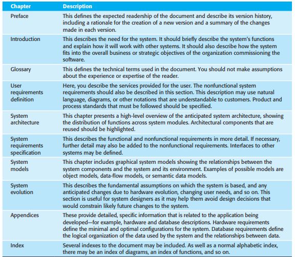
too many details.19 In the architectural design stage, the developer designs as the name suggests the architecture of the software that is to be implemented. During this stage of the developmental process, the software that is to be implemented is broken down into individual components, and the interaction between them are de- fined. (Sommerville 2016, 201.) A tool that can be used during the architec- tural design stage is a class diagram as it shows the different components and their interactions (Figure 6) Figure 6: Class diagram example (Visual Paradigm no date). Database design is a design process step that could be considered part of ar- chitectural design. In this step, the database for the software is designed, in- cluding the software’s data structure and its representation. This step is not al- ways necessary as it depends on whether the software uses an existing data- base or if it requires the creation of a new one. (Sommerville 2016, 57.) An en- tity relationship diagram is a good tool for database design as it provides a vis- ual aid concerning the different entities in the software that contain data and how they relate to each other. An example of an entity relationship diagram is shown in Figure 7.
20

Figure 7: ER-diagram example (Lucidchart no date).

In the interface design stage, the user interface is designed to be as easily us-
able as possible for the end user (Bell 2005, 53). There are three types of in-
terfaces that a program can use (Bell 2005, 54-55):
   •   Command line interface that runs commands through the command
       line.
   •   Menu interfaces that use choices to run commands. For example, an
       ATM uses a menu interface.
   •   Graphical User Interface (GUI) that directs the software through an in-
       teractive interface where selections are made using a mouse.

When designing the user interface, the developer should keep in mind the dif-
ferent kinds of users that might use the software and as such the interface
should be designed in a way that accounts for the differences between users.
Alternatively, an interface can be created from the start to be used in different
ways (Bell 2005, 56). In his book, Bell (2005, 57) describes three principles
that should be kept in mind during the designof the user interface:
   •   Learnability - the interface is easy to learn how to use.
   •   Flexibility - the interface must account for different ways of using it.
   •   Robustness – the interface must properly inform the user about what is
       going on.
This design stage can also include prototyping the interface to see if it meets
the requirements set for the interface (Bell 2005, 64). The detailed design
stage involves creating the detailed designs for the different modules and
components of the software (Bell 2005, 24).
21
2.3 Implementation
The implementation stage is a vital part of the software engineering process
as it is during this phase that the software is actually programmed. The imple-
mentation stage is linked deeply with the requirement specification and design
stages as they provide the framework upon which the developer starts to cre-
ate the software. If the previous stages have provided output that follows most
of the practices discussed in the respective chapters of this thesis, the devel-
opers’ job becomes much easier as they do not have to spend time seeking
clarification about the clients’ intentions. The implementation is based around
documents and outputs made in the previous steps, such as the use case dia-
grams and documents, class diagrams and design documents.
According to Sommerville (2016, 212), there are three aspects of the imple-
mentation stage that are not usually covered in programming texts:
1. Reuse. The developer should use as much existing code as possible.
2. Configuration management. The developer should keep track of the
versions of the components created during the development process,
so the wrong component version is not used during development.
3. Host-target development. The software is developed on one computer
(host system) and the executable file is run on another computer (target
system).
There are numerous different ways to approach the programming of the soft-
ware. In this thesis, two approaches are examined: object-oriented and struc-
tured. In the object-oriented approach to programming, methods and variables
that are linked to each other are encapsulated together in a class. Classes
themselves are in essence abstractions which allow the developer to reuse
pieces of code. In an object-oriented approach, variables are, in general, pri-
vate, and methods are public. The user interacts with the methods, and the
methods interact with the variables. (Bell 2005, 200-208; Kent 2014, 169.) A
key component of object-oriented programming is the concept of inheritance.
If the objects that are being created are very similar, but one is a specialized
case of the other, the former has inherited from the latter. In his book, Kent
(2014, 169) provides an example of how inheritance works: a class called22
RawTurtle (Figure 8) was created first and then a subclass called Turtle was
created (Figure 9). Turtle inherits the attributes from the RawTurtle class.
Figure 8: Main class (Kent 2014, 170).
Figure 9: Subclass (Kent 2014, 169).
In the structured approach to programming, it is said that programs are com-
posed of only three components (Bell 2005, 88):
• Sequences i.e the program instructions which are written in the order
they are executed.
• Selections. If-then-else program statements.
• Repetitions. While-do program statements.
In the structured approach, a program has only one start and exit point and it
can consist of multiple components that follow this approach (Bell 2005, 88;
Bell 2005, 97). In addition to these two approaches, there are many other
ways to program a software product.23
2.4 Testing
Testing has two main purposes in the software engineering process. The first
is to confirm that the requirements set during the requirements specification
stage are satisfied (validation testing), and the second is to finds flaws, or
bugs that stop the software from functioning as specified (defect testing)
(Sommerville 2016, 227). In addition, a software product also tends to go
through the following types of testing:
• Development testing where the software is tested during development
• Release testing where the completed version of the software is tested
• User testing where the users test the software in their own environ-
ment. (Sommerville 2016, 231.)
As mentioned before, development testing takes place during the develop-
ment process of the software and has three separate stages. The first of these
testing stages is unit testing. In unit testing, the tester focuses on testing the
software’s individual components and functions. (Sommerville 2016, 233.)
The second type of development testing is integration testing in which numer-
ous software components are integrated to form complete systems and
tested. There are three different ways to approach integration testing. The first
is the big bang approach, in which all the parts of the final system are tested
without prior unit testing. This approach presents the risk of not being able to
locate the component causing an error in the software. The second approach
involves first doing unit testing and then performing the big bang testing. The
third approach to integration testing is incremental testing. In this approach, a
component of the software is tested before another component is linked to it
and this is repeated until all the components have been tested. This approach
provides a way to find faults in the components more easily. Since the compo-
nents are combined one at a time, the latest of the added components is the
most likely cause of any faults. (Bell 2005, 277.)
The last type of development testing is system testing where the entirety of
the software system is tested. The purpose of system testing also tends to be
to detect defects within the program (Sommerville 2016, 245).24
Release or acceptance testing is rather like system testing, although with
some key differences. During release testing, a completed version of the soft-
ware is tested instead of a version that is still in development. Also, during re-
lease testing, the software is tested to see that it meets all the users’ require-
ments while system testing tends to test simply the general functionality of the
program.
The last of the main testing phases is user testing. User testing tends to take
place during system testing. During this phase, the intended users of the soft-
ware test it in their own environments. User testing is an important part of the
development process as even if the software development and release testing
were performed, the users’ actions and operating environments can cause be-
haviors that were not detected before or identify bugs that were not found dur-
ing the preceding stages. (Sommerville 2016, 249.) Sommerville (2016, 249)
describes three different types of user tests that can be performed:
• Alpha testing where the users test the software during development, so
this type of testing overlaps with development testing. Alpha testing
tends to be performed by only a selected group of people.
• Beta testing where the software is released for a wider audience and
their feedback on possible flaws or bugs is gathered.
• Acceptance testing which is the final testing before the software is re-
leased. During this stage, it is determined if the software meets all set
requirements and is in acceptable condition.
An important aspect of testing is the V-model of software development. It is
also known as a plan-based software process. In the V-model, there are test-
ing related tasks for all the stages of software development except for the im-
plementation stage (Figure 10).
Figure 10: V-model example (Sommerville 2016, 60).25 During the requirements specification and design stages, this entails the crea- tion of test plans for the integration and user test phases. If the V-model is used, these plans are what direct the testing of the software. (Sommerville 2016, 59-60.) Testing also involves the creation of test cases which are written specifications about what kind of input should be given to the program and what kind of output is expected. The general process of testing which is fol- lowed from development testing to user testing begins with the creation of test cases and ends in a test report. While test cases cannot be generated auto- matically, the execution of the test cases can be automated as seen in the testing process flowchart in Figure 11. (Sommerville 2016, 230; Figure 11.) Automated testing can save a great amount of resources and time that can then be allocated to other matters. Figure 11: Testing process flow (Sommerville 2016, 230). 2.5 Deployment and maintenance The deployment stage is the phase of the development process where the completed software is released to its users. When the software has been com- pleted and it has passed the acceptance tests and the users, developers and testers so agree, the software is released for its intended users. The maintenance stage takes place after the product is released. It encom- passes actions that modify the software or help maintain its functionality. There are two types of maintenance that are used. The first type is remedial maintenance which focuses on fixing the flaws found in the software after its release. The second is adaptive maintenance that involves either adding new features to the software or modifying the current software to account for changes in its operating environment, such as operating system and hard- ware. (Bell 2005, 11.)
26

In general, maintenance tends to be the most expensive part of the software
development process. As seen in Figure 12, the cost of maintenance can take
well over half of the total costs of the entire development cycle, and Figure 13
shows that the addition or modification of features is the costliest of all mainte-
nance processes.

Figure 12: Software development cost graph (Bell 2005, 12).

Figure 13: Maintenance cost distribution (Sommerville 2016, 272).

There are numerous factors that cause the cost of maintenance to rise to such
high levels. One factor is the age of the software. This is due to the fact that
any changes made to the software are likely to change the structure of its
code which in turn makes it harder to understand and modify. Another reason
is that if maintenance and development duties are separated between differ-
ent parties, the developers have no incentive to make their code maintainable
27

since they will not be responsible for its maintenance. If people not involved in
the development of the software are assigned to maintain it, they must put in
time and effort to understand the software before they can properly do any-
thing with it. This also leads to increased maintenance costs. (Sommerville
2016, 272-273.)

2.6   Use of software engineering principles in the commissioner’s appli-
      cation

The commissioner’s application did not follow all the different principles de-
scribed in the previous chapters. This is largely due to the software being
much smaller in scale compared to large-scale software, which tend to follow
the principles more closely. The use of the principles in the creation of this
particular application is described below stage by stage.

The requirements specification stage was short due to the limited functionality
of the software. The requirements specification was mostly made during a
meeting with representatives from Produal. Their desired requirements for the
application were documented in a text file to serve as as a basis for the actual
specification.

The design stage mostly entailed the making of a general outline concerning
what different components each of the functional requirements should contain
and how they could be created. This allowed the application to have a general
architectural design outline. The details of the design outline became more
specified as progress was made with the development process. The design
process also contained the interface design phase as the commissioner’s ap-
plication contains a GUI. The interface design phase was conducted by proto-
typing the GUI and refining its visual appearance in meetings with the team
leaders from Produal.

The implementation stage followed the structured programming approach.
The implementation consisted of different classes which contained the differ-
ent application functions. Thus, the program is object-oriented, even if it also
features elements of modular programming due to the functions basically be-
ing subroutines for specific tasks.
28 During the testing phase of the application, the three main testing types were all involved. The development testing mostly took the form of component test- ing due to the application’s programming functionalities relying upon the GUI. More specifically, the primary function takes the form of a command line argu- ment that must be based on the choices made in the GUI. The system testing showed no obvious flaws. The release and acceptance testing was done in Produal’s production environment, and the tests showed some performance and GUI issues which made it imperative that the application was returned to the implementation stage to further optimize the program and fix the issues found with the GUI. After the identified issues were fixed, the application was deemed to meet the requirements and acceptable for deployment. A user manual was made during the deployment phase and it is presented in Appen- dix 1. In general, the operating procedure of the waterfall model was not strictly fol- lowed as some parts of the process overlapped with others. For instance, parts of the requirement specification process were done during the imple- mentation stage due to the client wanting new features that were not dis- cussed during the original meetings where the requirements were defined. The program was released for use in Produal’s production environment, and the application was installed on some of their computers. The application is currently in use at Produal and has been moved to the maintenance phase. A maintenance manual is currently under construction. 3 TOOLS AND TECHNOLOGIES This chapter describes the tools and technologies used in the creation of the commissioner’s application. Both physical hardware tools and different kinds of software languages and libraries were used in the creation of the applica- tion.
29

3.1     PICkit debuggers and programmers

PICkit is a series of physical in-circuit debugger and programmer products
produced by Microchip Technology Inc for the purpose of programming micro-
controllers (Microchip 2020b). The commissioner’s application supports two
types of PICkits, PICkit 3 and PICkit 4.

PICkit devices are powered through an USB port, and in the case of PICkit 4
they can be powered from the target device i.e.the microcontroller that the
PICkit programs. PICkits 3 and 4 have two modes for programming PICkits.
The first mode allows programming the target device directly through a com-
puter by using the MPLAB X IDE or IPE. The second mode involves the set-
ting of the PICkit to Programmer-to-Go mode. In order to set the PICkit to Pro-
grammer-to-Go mode either the IDE or IPE is used to create a device memory
image that is then uploaded to the device’s storage, in PICkit 3 to internal
memory and in PICkit 4 to an inserted MicroSDHC card. Files that are used to
create the image are usually HEX files. If the PICkit is in Programmer to Go-
mode, there is no need to use the IDE or IPE to program the target device
since in Programmer to Go-mode all the needed information is stored in the
PICkit. (Microchip 2020b.) However, one PICkit can only store one image at a
time.

3.2 MPLAB X IDE, IPE and IPECMD

MPLAB IDE X is an IDE (Integrated Development Environment) specifically
tailored to allow its user to control, debug and develop applications for Micro-
chip’s embedded controllers i.e. controllers designed for one task (Microchip
2019). MPLAB IPE is used for directing a PICkit device’s programming func-
tions, and in contrast is often used in a production setting (MPLAB X IDE
User’s Guide 2020). IPECMD is a command line interface that runs the same
programming functions as the IPE through the computer’s command line.

3.3     Python

Python is an interpreted, object-oriented and high level programming lan-
guage featuring high-level built-in data structures as well as dynamic typing
30

and binding that provide a platform for rapid application development. The
easy readability of its code reduces the maintenance costs. (What is Python.)

Python also provides developers with numerous advantages as described by
Parikh (2018), for example:
          o The simple syntax makes it simpler to learn than some other lan-
            guages.
          o Comparatively lower line count allows to perform the same tasks
            with less effort. For example, compared to C++, a task that takes
            7 lines can be done in 3 lines in Python.
          o Python’s large community gives access to ready libraries for al-
            most any kinds of tasks that need to be performed by a program.

Python was used as the exclusive programming language for the commis-
sioner’s application due to the large amount of online documentation regard-
ing various problems that might be faced, easy syntax and the ability to
quickly write code for prototype features and the extensive amount of libraries
for the tasks the application must be able to perform.

3.4   Kivy

Kivy is a graphical user interface library for Python. It allows the developer to
make user interfaces for many different platforms. Kivy is currently the only vi-
able way to make interfaces in Python for Android (Phillips 2014, 1).

Kivy has its own language syntax called kvlang that allows the user to rapidly
design interfaces for an application by simply writing it to a separate kv file
(Phillips 2014). Kvlang is an excellent tool for rapid deployment of GUIs as its
syntax is close to standard written English and thus has a minimal learning
curve. Kvlang also makes the code easier to manage since all data required
by the GUI is stored in one sub-file which can be called from the main file.
Phillips (2014) shows the following example on how to bring the classical
“Hello World” message to the screen (Listing 1):
31 Label: text: "Hello World" Listing 1: Kvlang "Hello World" example (Phillips 2014, 7) Kivy has numerous widgets that can be used, such as labels, buttons and spinners. The attributes of the widgets such as size, position or color can be modified freely by the user. A developer can also use kvlang to create their own custom widgets by combining existing widgets. (Phillips 2014, 9-10.) 4 IMPLEMENTATION In this chapter, the implementation of the different parts of the application is described, and explanations and reasons for the choice of solutions are pre- sented. In the subchapters, when individual keywords from the source code in Appendix 2 are referenced, they are identified in boldened Consolas font, size 12. 4.1 The GUI (Graphical User Interface) The development process for the application began with the design and crea- tion of the GUI as the other features are dependent on the elements contained in the GUI. The GUI was developed in cooperation with the production team leaders. The first design was created with the use of draw.io and presented to the team leaders to showcase the general visual appearance of the GUI and the place- ment of the elements contained within the GUI (Figure 14).
32

Figure 14: First concept of the GUI.

The GUI was further developed based on feedback gathered from subsequent
follow-up meetings with the team leaders until it the iteration seen in the final
version was achieved. The largest change made in the process was that the
choice for the amount of power the PICkits were to supply to the target device
was removed, as it was deemed better if the power setting was included in the
configuration file so that there would be no need to select it every time as the
products always use the same voltage when they are being programmed.

The final version of the GUI is presented in Figure 15. For the final version,
the “Add Product” and “Refresh the product list” buttons were added because
33

the scope of the functionalities was increased later in the developmental cycle.

Figure 15: Final GUI appearance.

In general, the GUI for the application consists of Spinner and Button widgets
from the Kivy library. The Spinners were chosen for the widgets used to dis-
play the lists of products and other options because their values could easily
be changed, which offers a far quicker way to create a dropdown-style selec-
tion method than Kivy’s own Dropdown widget. The Dropdown widget is a bet-
ter option if a developer needs different widgets in the dropdown menu. For
the commissioner’s application, only the ability to choose from different op-
tions was needed, a requirement which the Spinner widget met perfectly.

Kivy has multiple different layouts that can be used to arrange the GUI ele-
ments. The different screens for the application and their contents are defined
in their separate classes, each having their own layouts, which are defined as
the parent class for the screen. For example, the main menu could be defined
like this: class MainLayout(FloatLayout) (Appendix 2). For the main
menu, the FloatLayout was used since it allows the different GUI elements
to be freely moved around the screen. The different elements for the GUI are
initialized in the init function of the class in the following manner (Listing 2):
34

self.deviceprogram = Button(text="Program Product",
                          size_hint=(.2, .15),
                          pos=(550, 100))
Listing 2: Initialization of a GUI element (Appendix 2).
As seen from the above example, the widgets are initialized by defining their
text, size and position. The self-keyword seen before the widget’s name refers
to an instance of the class, in this case MainLayout, and is used to declare
parts of the class (Parker 2016, 222). After the different attributes of the widg-
ets are defined, they are added to the layout using Kivy’s addwidget com-
mand that takes the widget as an argument. For example, the “Program Prod-
uct”-button seen before is added with:

self.add_widget(self.deviceprogram)
Listing 3: Adding the GUI element (Appendix 2)

The main menu’s GUI also gives the user information about the product that is
about to be programmed by using Python’s Configparser library in the up-
datelabel function. The configparser is initialized in the MainLayout class.
(Appendix 2.) The updatelabel function opens the ProductList.ini configura-
tion file with the Configparser and reads the text from the currently selected el-
ement from the Choose Product Spinner (Appendix 2). As the “Choose Prod-
uct” Spinner’s values are taken directly from the section names in the configu-
ration file, the updatelabel function reads the product’s processor type and
power settings from the section corresponding to the product’s name. (Listing
4)
self.parser.read("ProductList.ini")
produalprocessor = self.parser.get(self.produalproduct.text, 'Processor')
produalpower = self.parser.get(self.produalproduct.text, 'Power')
produalhex = self.locatehex()
self.infobox.text = 'This will contain info on product to be programmed\n Chosen product:%s \n
Processor:%s \n HEX:%s\n PICKit Power output:%sV\n' % (self.produalproduct.text,
produalprocessor, produalhex, produalpower)

Listing 4: Updatelabel functionality (Appendix 2).

The locatehex function (Appendix 2) presented in Listing 4 uses Python’s
glob library in conjunction with the Configparser to locate the file for the cho-
sen product. In a similar fashion to the updatelabel function, the parser is
used to find the defined filepath in the configuration file.
35 This file path is then used as an argument for the glob function (Appendix 2) of the glob library to locate all the files that match the defined file path. Be- cause the glob library allows for the use of wildcard characters, the user can leave parts of the path open by using *. For instance, should the defined path be C://file*.png, the glob function would locate all PNG files with file in their name in the root C directory. The glob library was chosen because it allows the use of wildcard characters to help account for any future updates, since the path in the configuration file can simply use the * character to mark any parts of the filename that are likely to change when the product’s program is updated. As the glob function creates an array of all matches (glob – File- name pattern matching), the locate hex function sorts the matches by modifi- cation date and uses the most recent one. For the other screens in the application, Kivy’s Popup widget was used be- cause it allows the creation of other screens without having to use Kivy’s Screenmanager functionality to handle the transitions between the screens. The use of separate screens was considered unnecessary since, after all, the other screens are only used for a short moment. The Popup function creates a popup screen that contains the layout and elements as defined by the user. 4.2 Programming a Produal product and programming PICkit The main functionality of the application is to program Produal’s products by calling IPECMD through the command line using Python’s sub-process library. The programming functionality begins after the user has made all the choices in the main menu. After the user presses the “Program Product” button, the program calls the run_all function that first calls the popup function to create a Popup that contains the progress bar and the buttons for programming a product and returning to the main menu. (Appendix 2.) After the popup is called, run_all defines the length of the progress bar to be equal to the cho- sen number of PICkits multiplied by 100 (Listing 5).
36

maxprogress = int(self.pickitnumber.text) * 100
self.p.max = maxprogress
Listing 5: Setting the progress bar maximum value (Appendix 2)

An array called threads is created in run_all to store all the separate calls to
the programming function. Using a for-loop, separate threads for each number
in the range of 1 to the chosen number of PICkits are created and stored in
the array. The thread operator sends the current number in the loop and
maxprogress as arguments to the programmer function. Later in this chapter,
the current number in the loop will be referred to as CNL (Current number in
loop). (Appendix 2.) The end of the range is defined as the chosen number of
PICkits that is read from the corresponding GUI element plus one. The reason
1 is added to the number is due to the way Python’s range function works.
The range is calculated until it is the final value minus 1. For example, if a
range from 1 to 4 is defined, the actual numbers calculated are 1, 2 and 3.
(Python range () no date.) Threads were used to allow the different calls to the
programming function to be run as concurrently as possible.

After the array is filled with the correct number of threads, each of the threads
is started using a for loop. The for loop ensures that no other threads are run-
ning before starting a new thread. This leads to the functionality of the pro-
grammer function. The function first uses the Configparser (Chapter 4.1) to
read the chosen product’s processor type and power settings while adding a
message about which PICkit is running the function by utilizing the CNL sent
from the run_all function (Figure 16).
You can also read