Installation and Commissioning manual - Aries ground source heat p ump - WWW.GEBWELL.COM
←
→
Page content transcription
If your browser does not render page correctly, please read the page content below

Installation and Commissioning manual
    Aries ground source heat p ump

              WWW.GEBWELL.COM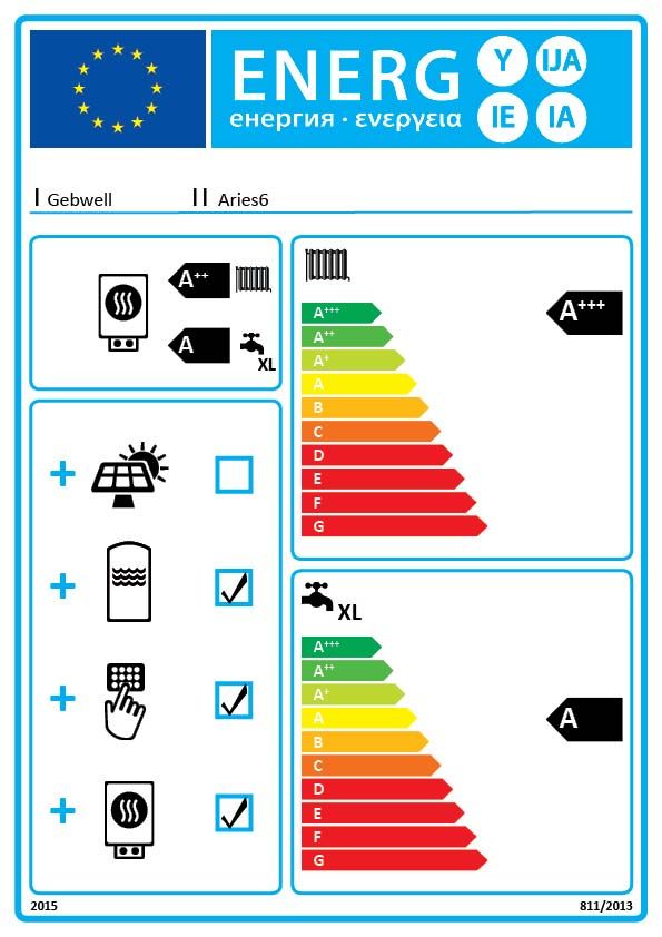
Contents
1      INSTALLATION RECORD: ............................................................................................................................................................................................ 7
2      GROUND SOURCE HEAT AND GROUND SOURCE COOLING .............................................................................................................................. 9

     2.1         Heat from the ground .............................................................................................................................................. 9
     2.2         Ground cooling ....................................................................................................................................................... 9
     2.3         Operating principle of a heat pump......................................................................................................................... 9
     2.4         Heating functions .................................................................................................................................................. 10
     2.5         Tips for making savings ........................................................................................................................................ 10
3      IMPORTANT: ................................................................................................................................................................................................................. 11

     3.1         Serial number ........................................................................................................................................................ 11
     3.2         Safety instructions................................................................................................................................................. 11
     3.3         Hazardous substances ........................................................................................................................................... 11
4      DELIVERY AND HANDLING...................................................................................................................................................................................... 11

     4.1         Content of the delivery ......................................................................................................................................... 11
     4.2         Optional accessories ............................................................................................................................................. 11
     4.3         Storage .................................................................................................................................................................. 11
     4.4         Transportation ....................................................................................................................................................... 11
     4.5         Handling the front door......................................................................................................................................... 12
     4.6         Detaching the cover of the control unit ................................................................................................................. 12
     4.7         Pulling out the compressor module....................................................................................................................... 12
     4.8         Removing the packaging....................................................................................................................................... 13
     4.9         Heat pump placement ........................................................................................................................................... 13
5      DIMENSIONS AND PIPE CONNECTIONS ................................................................................................................................................................ 15

     5.1         Pipe connections ................................................................................................................................................... 15
     5.2         Heat pump dimensions.......................................................................................................................................... 15
     5.3         Heat pump components ........................................................................................................................................ 16
     5.4         Heat pump sensors ................................................................................................................................................ 17
6      PIPE INSTALLATION ................................................................................................................................................................................................... 18

     6.1         Collector ............................................................................................................................................................... 18
     6.2         Heat supply circuit ................................................................................................................................................ 20
     6.3         Domestic hot water system ................................................................................................................................... 21
7      ELECTRICAL CONNECTIONS .................................................................................................................................................................................... 22

     7.1         General.................................................................................................................................................................. 22
     7.2         Power supply ........................................................................................................................................................ 22
     7.3         Connecting the sensors ......................................................................................................................................... 23
     7.4         Connecting the domestic hot water circulation pump ........................................................................................... 23
     7.5         Continuous alert .................................................................................................................................................... 23
     7.6         External control to the source pump ..................................................................................................................... 24
     7.7         Connecting accessories ......................................................................................................................................... 24
     7.8         Connecting an expansion card .............................................................................................................................. 24
     7.9         Heating control group (accessory) ........................................................................................................................ 24
8      FILLING .......................................................................................................................................................................................................................... 25

     8.1         Filling the heating and domestic hot water side .................................................................................................... 25
     8.2         Filling the collector ............................................................................................................................................... 25
     8.3         Pressurising the collector ...................................................................................................................................... 25
     8.4         Pressure-test of the collector ................................................................................................................................. 25
9      CHECK-UPS BEFORE STARTING THE HEAT PUMP ............................................................................................................................................. 26
10     STARTING UP THE HEAT PUMP FROM THE OPERATOR UNIT ......................................................................................................................... 26

     10.1        Purging the air from the accumulator coil ............................................................................................................ 26
11     STARTING UP FROM GEBWELL SMART APPLICATION..................................................................................................................................... 26

     11.1        Downloading the Gebwell Smart app ................................................................................................................... 26
     11.2        Obtaining maintenance rights ............................................................................................................................... 26
     11.3        Logging into the application ................................................................................................................................. 27
     11.4        Device identification ............................................................................................................................................. 28
     11.5        Connecting to the heat pump’s Wi-Fi network ..................................................................................................... 28

2                                                                                                                                                                    Aries Installation and Commissioning manual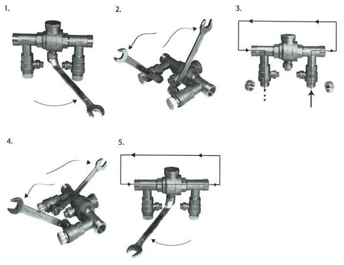
11.6        Entering heat pump’s Wi-fi settings on smart device............................................................................................ 29
     11.8        Operation without the collector and operating during construction ...................................................................... 33
     11.9        Purging the collector ............................................................................................................................................. 33
12     HEAT PUMP SETTINGS ............................................................................................................................................................................................... 33

     12.1        HEAT PUMP ........................................................................................................................................................ 33
       Time and date................................................................................................................................................................. 33
       Language selection......................................................................................................................................................... 33
     12.2        DOMESTIC HOT WATER .................................................................................................................................. 33
     12.3        HEATING ............................................................................................................................................................. 34
13     HEAT PUMP MAINTENANCE AND SERVICING .................................................................................................................................................... 36

     13.1        Inspections ............................................................................................................................................................ 36
     13.2        Drainage of the hot water tank (LVV1) ................................................................................................................ 36
     13.3        Drainage of the heating system ............................................................................................................................. 36
     13.4        Drainage of the collector ....................................................................................................................................... 36
14     FAILURES ...................................................................................................................................................................................................................... 37

     14.1        Alerts ..................................................................................................................................................................... 37
     14.2        Troubleshooting .................................................................................................................................................... 37
     14.3        Troubleshooting table............................................................................................................................................ 38
15     TECHNICAL DETAILS ................................................................................................................................................................................................. 41
16     EXAMPLE VALUES FOR HEAT PUMP SETTINGS FOR DIFFERENT HEATING NETWORKS ....................................................................... 42
17     SERVICE LOG................................................................................................................................................................................................................ 43
18     ENERGY LABEL ........................................................................................................................................................................................................... 44

APPENDIX 1: DECLARATION OF CONFORMITY
APPENDIX 2: ELECTRICAL DIAGRAM

v1-5 08072019                                                                                                                                                                                                                   3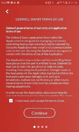
KEEP THE OPERATION INSTRUCTIONS IN THE IMMEDIATE VICINITY OF THE DEVICE!

Read the instructions carefully before installing, adjusting or servicing the device. Always follow the instructions. Ask the
installation technician to complete the installation log. The manufacturer’s warranty is only valid with an installation log.

Fill in the details below. If there are failures with the device, these details must be available.

    Ground source heat pump model:                                 Serial number:

    HVAC company:                                                  Name:

    Installation date:                                             Phone:

    Electrician:                                                   Name:

    Installation date:                                             Phone:

MARKING:
The CE mark is the manufacturer’s declaration that the product conforms to EU legal requirements. Gebwell Ltd affirms that
the product meets all of the requirements of relevant EU directives. The purpose of the CE mark is to facilitate the free
movement of goods on the internal market in Europe.

4                                                                                           Aries Installation and Commissioning manual
Gebwell Ltd.
Patruunapolku 5, 79100 LEPPÄVIRTA, tel 020 1230 800, info@gebwell.fi
issues the product,
Aries heat pump
a warranty regarding manufacturing and material faults, with the following contents.
Warranty period and start date The customer is obliged to perform a visual check on the product
before the installation, and it is not allowed to install a product
A two- (2) year warranty will be issued to this product, counting that is clearly faulty
from the product delivery date.
The warranty does not cover malfunctions, which have been
Two copies of the commissioning and warranty protocol will be caused by
delivered with the heat pump. The installer / reseller of the heat
pump fills the said protocol in and goes over it with the customer. the transportation of the product
Both Parties confirm they have gone over the protocol, and the carelessness of the product operator, the overload
accept the terms of warranty with their signature. The customer’s of the product, the failure of adhering to the operating
copy of the warranty protocol must be stored, and presented on
request. The other copy must be delivered to the factory within instructions or maintenance
1 month from the product commissioning date. The warranty is circumstances beyond the guarantor’s control, such
not valid in case the commissioning and warranty protocol has as voltage fluctuations (the maximum range of
not been filled in correctly, or if the factory copy has not been voltage fluctuations is +/- 10%), lightning, fire or
returned to the factory. accidents other than those caused by the repair work,
Warranty contents maintenance or structural changes done by authorised
resellers
The warranty extends to all manufacturing and raw material
faults that have occurred in this product during the warranty product installation or positioning on the operating
period, as well as the direct expenses related to the changing of site, which is in contradiction with the installation,
these devices. operating and maintenance manual, or otherwise
incorrect.
The buyer is responsible for any device malfunctions caused by
the storage conditions between the delivery and commissioning The warranty does not extend to the repair of defects that are
date (cf. installation, operating and maintenance manual; insignificant as far as the product’s operating condition is
storage). concerned, such as surface scratches. The warranty does not
5-year component warranty extend to the normal adjustments of the product as outlined in
the operating manual, operation training visits, maintenance and
In addition to the normal product warranty, a five- (5) year cleaning measures, or such work which is caused by the neglect
component warranty will be issued to the heat plate exchangers, of safety or installation regulations or the settlement of this on
starting from the product delivery date. the installation site.
The component warranty does not extend to the direct or indirect The warranty terms outlined in the joint recommendation of the
expenses caused by the changing of a component. Otherwise, all Association of Finnish Metal and Engineering Industries and the
terms and limitations of the product warranty apply for the Finnish Competition and Consumer Authority are observed to
component warranty, as well. such an extent which has not been separately mentioned above.
Warranty limits The warranty becomes void, if the product is
The warranty does not extend to the expenses (travel, power repaired or altered without Gebwell Ltd.’s permission
consumption, etc.) caused by a malfunctioning device, the used for a purpose, for which it has not been intended
buyer’s production loss, loss of earnings or other indirect
stored in a humid or otherwise unsuitable location
expenses.
(cf. installation, operating and maintenance manual).
This warranty has been given on the condition that the product
is working in normal operating conditions, and that the operating What to do if a malfunction occurs
instructions are followed carefully. The liability of the guarantor If a malfunction occurs during the warranty period, the customer
is limited according to these terms and conditions, and the must immediately (normally within 14 days) notify the
warranty does not extend to such damage as the product may authorised Gebwell reseller from whom the product was bought.
cause to another item or person. The notification must include which product has malfunctioned
The warranty does not extend to direct personal injuries or (product model, serial number), the details of the malfunction in
damage to property caused by the delivered product. as much detail as possible, as well as the circumstances when the
malfunction has developed and/or occurs. The warranty form,
The warranty presupposes that the installation has followed all correctly filled in at the handover time must be submitted on
valid regulations, generally accepted methods of installation and request. Appealing to a warranty-period notification is not valid
installation instructions given by the manufacturer of the after the warranty period is over, unless the notification has been
product. submitted in writing during the warranty period.
The warranty does not extend to or is not valid in case the The notification must be submitted immediately after the
product is used in any other way than required by the sizing. malfunction has been discovered. If the notification is not
v1-5 08072019 5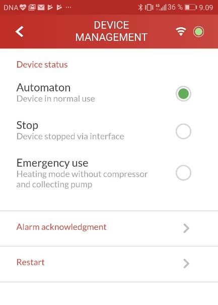
submitted immediately once the buyer has noticed the warranty terms carefully and find out the product’s
malfunction, or when the buyer should have noticed the model and serial numbers
malfunction, the buyer loses the right to appeal to this warranty. all parts belonging to a device must be included when
Maintenance service in Finland the device is returned
the returned product must be closed in such a way,
Maintenance work for this product, during the warranty period
and after the warranty period, is performed by the maintenance that handling it would not cause health or
organization authorised by the manufacturer, throughout the environmental hazards.
entire estimated economic life of the heat pump.
A device changed on the basis of the warranty is the property of
the device manufacturer. Gebwell Ltd. reserves the right to
decide how, where and who will perform the repair work or
How to submit a service request
change that is at the manufacturer’s responsibility.
All warranty repairs, service requests and orders for spare parts
Gebwell Ltd. is not liable for the breakdown of a wrongfully
will primarily be submitted directly to the authorised Gebwell
installed device.
reseller that sold/delivered the product. Before submitting a
service request, the following things must be taken into The device can only be repaired by a professional. Incorrect
consideration: repair work and settings can cause danger for the user, the
malfunction of the device, and weaken the efficiency of the
read the installation and maintenance manual device. The visit of a retailer or a service agent is not free of
carefully and think whether you have used the device charge even during the warranty period, in case the device has to
in accordance with the instructions in the manuals be repaired due to incorrect installation, repair or adjustment.
before submitting a warranty repair request, ensure
that the warranty period is still valid, read the
6 Aries Installation and Commissioning manual
1 INSTALLATION RECORD:
The heating system must be inspected in accordance with applicable regulations before commissioning. The inspection must
be performed by a qualified person. The installation log should be completed before the equipment is handed over to the end-
user. A completed installation log is a precondition for the validity of the warranty.
 Inspected       Description                                         Comment

                 COLLECTOR:
                 Circulation direction checked
                 System pressure-tested
                 System rinsed
                 System bled
                 Fluid quantity in the collector
                 Strainer checked/cleaned
                 Expansion tank
                 Initial pressure of the expansion tank (0.5 bar)
                 Strainer/flow direction
                 Safety valve checked
                 Shut-off valves checked
                 Length of the collector           m
                 - If there are several loops, record the lengths:                                          m

                                                                     Checked by                                  (date)

                 HEATING SYSTEM:
                 System filled
                 Accumulator coil filled / bled (coil
                 accumulator)
                 System pressure-tested
                 System rinsed
                 System bled
                 Safety valve
                 Diaphragm expansion tank
                 Initial pressure of the expansion tank
                 Strainer checked/cleaned
                 Pressure measuring device
                 Shut-off valves
                 Filling valve
                 Buffer accumulator
                 Heating circuit control set
                 Circulation water pumps
                 Rotation direction of pumps
                 Actuators

                                                                     Checked by                                  (date)

                 DOMESTIC HOT WATER:
                 System filled
                 System pressure-tested
                 System rinsed
                 Safety valve
                 Pressure measuring device
                 Buffer accumulator
                 Hot water circulation

                                                                     Checked by                                  (date)

v 1-4 05022019                                                                                                            7
Inspected   Description                                  Comment

                ELECTRICITY:
                Building fuses
                Heat pump fuses
                Phase sequence
                Power supply
                Regulation group(s)
                Supply water sensor(s)
                Room temperature sensor
                Outdoor temperature sensor

                                                             Checked by                             (date)

                CONTROLLER:
                Room set point for the heating circuit
                Heating curve gradient set
                Minimum set point for supply water to the
                heating circuit
                Maximum set point for supply water to the
                heating circuit

                                                             Checked by                             (date)

                GENERAL:
                Wiring in accordance with the installation
                instructions
                Connection seals
                Device started up in accordance with the
                instructions
                Operation of the machine monitored on site
                for 30 minutes

                                                             Checked by                             (date)

                GUIDANCE FOR THE END USER:
                Adding fluid to the collector
                Increasing the pressure of the heating
                system
                Setting the heating regulation curve
                App user interface guidance

                                                             Checked by                             (date)

8                                                                         Aries Installation and Commissioning manual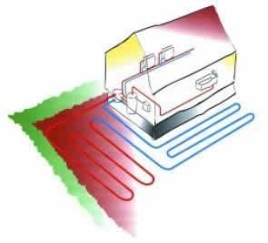
Watersystem as a heat source
2 GROUND SOURCE HEAT
AND GROUND SOURCE
COOLING
A well-designed ground source heating system with the
correct power values offers low operating costs and good
energy efficiency. The ground source heat pump enables
you to efficiently heat your indoor air and domestic hot
water. In the summer, the system can also cool indoor air
in an environmentally friendly way.
2.1 Heat from the ground
The ground source heat pump collects heat from the
ground and brings it into the building. Heat can be
collected using either a network of pipes embedded in a Further information about heat collection systems and
bored well, a heat collection pipe network installed close their designs can be found on the websites of Gebwell Ltd.
to the soil surface, or a network of pipes anchored to the and the Finnish Heat Pump Association (SULPU).
bottom of a body of water.
www.gebwell.com
www.sulpu.fi
Bored well as a heat source
2.2 Ground cooling
The low temperature of the brine can also be used to cool
your home. In the summer, free cooling energy can be
transferred from the ground using only a water circulation
pump. The ground source heating system can be
connected to the ventilation fan convector or an
underfloor heating/cooling system designed for cooling.
2.3 Operating principle of a heat pump
The heat pump consists of four main components
Evaporator
Compressor
Condenser
Expansion valve
Soil as a heat source The solar energy stored in the soil is collected by the brine
circulating in the heat collection pipe networks.
In the evaporator, the energy contained in the brine is
transferred to the refrigerant, which absorbs the heat
energy as it evaporates. The brine returns to the ground
approximately 3°C cooler than when it came. The brine
entering the heat pump can be no colder than -5°C.
The pressure and temperature of the refrigerant increase
in the compressor. The refrigerant also absorbs the heat
energy created by the compressor’s work.
The warm refrigerant is transferred into the condenser.
The condenser transfers the heat energy from the
refrigerant into the water circulating in the house’s heating
v 1-4 05022019 9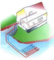
system, which distributes it to heat the building and the    Heating
domestic hot water with the help of a change-over valve.
The refrigerant condenses into a liquid state in the         The heat pump outputs heating water directly into the
condenser as it loses heat energy.                           building’s heating network. Automatic regulation
                                                             determines the set point for the supply water from the
The pressure of the refrigerant remains high as the liquid   heating circuit based on the set heating curve and the
refrigerant is transferred to the expansion valve. The       outdoor temperature measurement. The controller uses the
pressure of the refrigerant decreases in the expansion       set value for the supply water to determine the set point
valve, and the temperature drops to approximately -10°C.     for the heat pump, and the frequency-controlled
The expansion valve injects the correct amount of            compressor uses this value to set itself to the correct
refrigerant into the evaporator, where the heat energy       rotation speed in order to keep the temperature of the
transferred from the brine causes the refrigerant to         supply water at the set point. The room temperature sensor
evaporate.                                                   also affects the set point.
                                                             In order for the heat pump to operate at maximum
                                                             efficiency, the heating system and the collector must be
                                                             under ideal conditions. The difference between the
                                                             heating system’s output and return temperatures must be
                                                             5–8°C, and the difference between the collector’s output
                                                             and return temperatures must be 3–4°C. If the temperature
                                                             differences deviate from these values, the efficiency will
                                                             decrease, along with the savings. The heat pump’s
                                                             controller ensures the correct temperature difference for
                                                             the heat supply and the collection pump.
                                                             Factory settings:
                                                             Heating temperature difference: 5°C
                                                             Domestic hot water preparation temperature difference:
                                                             8°C
Figure: Functional description
                                                             Collector temperature difference: 3°C
1: Heat pump
2: Condenser                                                 2.5    Tips for making savings
3: Compressor                                                The heat pump is intended to generate the desired heat and
4: Evaporator                                                domestic hot water. The system attempts to meet these
                                                             desires by all available means within the limits of the set
5: Change-over valve                                         values.
6: Water circulation pump, heating/domestic hot water        Important factors affecting energy consumption are the
charge                                                       indoor temperature, the domestic hot water consumption,
7: Expansion valve                                           the temperature of the domestic hot water, the quality of
                                                             the house’s insulation, and the desired level of comfort.
9: Collection pump
                                                             Keep the aforementioned factors in mind when changing
9: Heat collection pipe, ground loop                         the device’s settings.
10: Heat collection pipe, bored well
11: Underfloor heating                                       IMPORTANT:
12: Radiator heating                                         Floor heating and radiator thermostats can have a negative
13: Hot water tank                                           impact on energy consumption. They reduce the flow rate
                                                             in the heating system, and the heat pump compensates for
                                                             this by raising the temperature of the network. This affects
                                                             the device’s operation by causing more electrical energy
2.4    Heating functions                                     to be consumed. Thermostats are only intended for
                                                             adjustments due to “free heat” (from the sun, people,
Domestic hot water                                           fireplaces, etc.)
The heat pump outputs domestic hot water based on the
tank’s operational measurement sensor (B3). The
temperature of domestic hot water can be selected from
the options, Eco, Normal or Comfort. This selection
affects the amount of hot domestic hot water. When
Comfort is selected, the heat pump also uses an electric
heater to heat domestic hot water.

10                                                                                Aries Installation and Commissioning manual
Refrigerant
3 IMPORTANT:
The heat pump contains a refrigerant that is harmful and
These installation instructions describe installation and hazardous to the environment. The refrigerant is in a
maintenance measures that should only be carried out by hermetically sealed refrigerant circuit in the compressor
a professional. module. If the refrigerant leaks into indoor premises, the
The installation instructions should be given to the room must be thoroughly ventilated.
customer in the manual folder. Heat collection liquid
3.1 Serial number The mixture of antifreeze agents, including ethanol, used
as the heat collection liquid are highly flammable. Avoid
The device’s serial number is on the ID plate, which is splashing the liquid on your skin.
attached on the cover panel of the control unit, as well as
on the back cover of the user manual.
Keep in mind that you will need to know the device’s
serial number whenever you contact the manufacturer, 4 DELIVERY AND
maintenance or support services. HANDLING
4.1 Content of the delivery
Gebwell Aries heat pump 1
Installation and maintenance manual 1
User instructions 1
Outdoor temperature sensor 1
Room temperature sensor 1
Safety valve for the heating circuit
G1/2” – 2.5 bar 1
Safety valve for the domestic hot water circuit
G1/2” – 10 bar 1
Power supply cable with plug (16A) 1
4.2 Optional accessories
Collector valve group
3.2 Safety instructions Installation set
Cooling extension for installation set
The following safety instructions must be kept in mind Heating pump extension for installation set
when handling, installing and operating the device. Heating control group
Only lift the device at the locations shown in the Domestic hot water buffer tank
instructions. Heating buffer tank
Domestic hot water circulation pump series
The metallic edges of the heat pump could injure your
Diaphragm expansion tank for the collector
hands when you are moving the unit. Use slash-
Diaphragm expansion tank for heating
resistant gloves to move the heat pump. Energy measurement
Always unplug the device before servicing.
Never jeopardise safety by bypassing safety devices.
The refrigeration compressor unit in the device must
4.3 Storage
only be serviced and repaired by a qualified person.
Do not rinse the heat pump with water. Before installation, the Aries heat pump should be stored
During installation, keep all of the device’s housing in its shipping package in a warm, dry place. If the device
panels intact to prevent water from splashing onto the is stored in a cold or humid environment, the electrical
device’s electrical components. components may get wet, causing failures in the operation
of the device at a later stage.
3.3 Hazardous substances
4.4 Transportation
Electricity
The panels on the exterior of the heat pump should be
The electrical components inside the heat pump carry a removed if the device is being brought into a confined
potentially fatal current. Unplug the device before you space, and replaced once the device has been moved
open the protective plate on the control unit or the inside. The heat pump can be tilted temporarily but it must
compressor module. not be left in a slanted position for long periods, even
during transportation. The maximum tilt angle for the heat
v 1-4 05022019 11pump is 45°. The heat pump should not be turned onto its
side. However, if it is necessary to turn the heat pump onto
its side for reasons such as transportation, the compressor
unit can be removed during transportation. However, the
heat pump must not be transported upside down. If it is
necessary to tilt the heat pump, the heat pump must be left
in the vertical position for at least two hours before
starting up to ensure that the lubricating oil in the
compressor flows into the right place. The heat pump
should only be lifted by the pallet. The device must be
transported to the place of installation on the pallet.
4.5 Handling the front door
The heat pump front door has to be removed during
operations inside the heat pump. To remove the front door,
lift it straight up. Lifting can be assisted with a foot at the 4.7 Pulling out the compressor module
bottom. To reinstall the door, lift the door so that the lip at
the bottom of the door goes into the slot on the bottom of The compressor module can be detached from the heat
the heat pump and the lip on the top of the door sits at the pump to facilitate transportation and servicing.
top of the heat pump. 1. Close the shut-off valves (VS1–VS4).
2. Open the insulation from beneath the shut-off valves
so that you can open the pipe system’s mounting nuts.
When you open the mounting nuts, hold on to the key
barrel for the flexible pipe underneath using the other
key.
3. Turn the shut-off valves of the collection pipes closest
to the edge into the horizontal position (the O-ring
seals permit this without squeaking).
4. Detach the two screws from the device frame of the
compressor module at the mounts on the front edge.
5. Pull the compressor module out using lifting straps
intended for this purpose.
6. Detach the pipes from the connections (valves VS1–
VS4).
4.6 Detaching the cover of the control unit
The cover of the control unit is attached with four hex
screws. You will need a 6-mm ring spanner or socket
wrench to open the cover.
12 Aries Installation and Commissioning manual7. Loosen the screws on the compressor unit mounts and The protective plastic can be retained to protect the heat
detach the compressor unit’s plugs from both the pump until it is started up.
electrical switchboard and the compressor unit.
Ensure that you have received the correct product with
the correct accessories.
Place the heat pump near the intended installation
location.
Lift the heat pump off the shipping pallet.
Use the adjustable feet to get the heat pump into a
horizontal and stable position.
Make sure the frame is not in contact with the
building’s structures, with the exception of the
adjustable feet.
4.9 Heat pump placement
8. Pull the compressor unit out.
The placement of the heat pump must take account of a
few factors related to safety, convenience and
serviceability.
The temperature of the placement location must be
between +5°C and +30°C. The installation space must be
4.8 Removing the packaging adequately ventilated. Water condenses on the cold
The product is packaged in protective plastic in such a sections of pipe in the collector if the space is very humid.
way that it can be installed without removing the plastic. The heat pump’s compressor (K1) generates a noise that
can be conducted along the structures of the house into
v 1-4 05022019 13other areas far away. It is advisable to use flexible components for pipe connections. The heat pump should be placed in a location where noise cannot be conducted in a way that adversely affects residential premises. If necessary, supplementary noise insulation can be installed in the wall structures between the heat pump’s installation location and residential premises, and additional rubber cushioning can be fitted beneath the heat pump’s feet. We recommend placing the heat pump in a separate utility services room. Noise can be prevented from travelling through structures by using solutions such as special floor structures in the area reserved for the heat pump. A cast floor that is separated from the building’s other areas can prevent noise from travelling through the floor and into residential premises. At least 700 mm of clearance should be reserved in front of the heat pump to allow the compressor unit to be pulled out for servicing. For the same reason, the device must not be installed below the floor surface. Adequate clearance should be left behind the heat pump to prevent vibrations from being transmitted onward. In addition, clearance of 600 mm should be reserved to the side of the heat pump if you would prefer to connect the collector’s pipes to either side of the heat pump rather than the top. When installing a factory-made installation group with the Aries heat pump, a clearance in accordance to the picture below should be reserved around the heat pump. Installation group installed on the side of the heat pump: Installation group installed onto the wall beside the heat pump: 14 Aries Installation and Commissioning manual
5 DIMENSIONS AND PIPE                                   5.2   Heat pump dimensions
  CONNECTIONS
5.1    Pipe connections

                                   Aries 6   Aries 12
BO1        Brine to the ground     28mm       28mm
BI2        Brine from the ground   28mm       28mm
WO1        Heating supply          22mm       28mm
WI2        Heating return          22mm       28mm
CI1        Cold water              22mm       22mm
HW2        Domestic hot water      22mm       22mm
HWC3 Hot water circulation         15mm       15mm

v 1-4 05022019                                                                       15
5.3 Heat pump components
TANK’S PROTECTIVE ANODE
DOOR LOCK
HOT WATER TANK (LVV1)
CONTROLLER
LINE PROTECTION
AUTOMATION CONTROL CENTRE
FLOW-THROUGH
RESISTOR (SV1)
SHUT-OFF VALVE CHANGE-OVER VALVE
(VS1/CHARGE OUTPUT) + ACTUATOR (VV1)
OVERHEATING PROTECTOR
FOR THE FLOW-THROUGH SHUT-OFF VALVE
RESISTOR (SV2) (VS2/CHARGE RETURN)
SHUT-OFF VALVE
SHUT-OFF VALVE
(VS4/BRINE FROM THE GROUND)
(VS3/BRINE TO THE GROUND)
INSIDE THE COMPRESSOR UNIT:
- HEAT SUPPLY PUMP (Q9)
- SOURCE PUMP (Q8)
- COMPRESSOR (K1)
- FREQUENCY CONVERTER (TM1)
- EXPANSION VALVE (PV1)
- EVAPORATOR (LS1)
- CONDENSER (LS2)
16 Aries Installation and Commissioning manual5.4 Heat pump sensors
Functional and measuring thermal sensors are installed in
the heat pump. The sensors are attached to components
and insulated from external heat. Some of the sensors are
located in the compressor unit module.
B2 Domestic hot water (tank)
B3 Domestic hot water (operation)
B21 Charge heating water supply (heating supply)
B71 Charge heating water return (heating return)
B91 Brine from the ground
B92 Brine to the ground
B81 Hot gas B2
B85 Suction gas
B21
B3
B91
B92
B85
B81
B71
v 1-4 05022019 176 PIPE INSTALLATION
6.1 Collector
When using PEM pipes 40 x 4.2 PN6.3.
Device Recommended Recommended
collector pipe active drilling
length (m) depth (m)
Aries 6 300 – 400 100 – 160
Aries 12 380 – 500 160 – 300
These figures are approximate example values. Before
commencing installation, the building’s heat requirement
should be precisely calculated. 1. Remove the cellular rubber insulation from the
end of the pipe
The maximum recommended length of one loop of the 2. Take note of the sensors when you make changes
collector is 400 m. If a longer heat collection pipe network
to the pipe network
must be installed, the networks should be divided into
3. Detach the collection pipes from the elbow fitting
several loops and connected in parallel. The connection
by pressing down on the plastic collar on the claw
should be made in such a way that it is possible to balance
coupling using a spanner.
the flows in the loops.
4. Detach the pipes from the top connection and turn
The collecting pipe network should steadily rise towards the elbow fitting in the desired direction.
the heat pump to prevent air pockets. If this is not possible, 5. If necessary, cut the pipe to the desired length.
purge valves should be installed at the high points. 6. Reattach the pipe by pressing on the elbow fitting
Insulate all of the collecting pipes in the building using
closed-cell insulation to prevent condensation.
Use rubber-insulated brackets for pipes.
Place the level expansion tank at the highest point on
the collector, on the inbound pipe before the heat
pump.
Mark the name of the brine liquid used on the level
expansion tank and in the installation log.
Install shut-off valves in pipe connections as close to
the heat pump as possible.
Make sure that the top of the heat pump and the
electrical equipment are entirely free of water during
operation.
Water may condense on the surface of the level
expansion tank. Locate the level expansion tank in a
place where condensed water is not able to drip onto
the heat pump.
Before installing the heat pump, rinse the collector pipe
Connect the collector’s valve group with the related
network to remove any impurities that may remain after
expansion tanks as shown in the diagram. The arrow
installation.
on the poppet seat indicates the flow direction. The
The collector connection must be selected before the valve group size is DN25. Do not connect pipes
device is put into position. The connection can be placed smaller than 28 mm.
on the right, left or behind instead of using a top The collector must be pressure-tested with 3 bars of
connection. At least 600 mm of clearance must be pressure and the test pressure must be sustained for at
reserved in the outbound direction. least 30 minutes.
Only connecting components designed for cold
conditions should be used in the collector.
18 Aries Installation and Commissioning manualConnection alternatives
Ground cooling
Ground cooling functions best when heat collection is
arranged using a bored well. During the summer, loops
The collector can be depressurised using the level installed in the soil or in lakes may be at such a high
expansion tank (EX1). The level expansion tank should be temperature that the required cooling power cannot be
installed at the highest point in the circuit so that air can obtained. Air within the collector should be allowed to
rise into the tank. Do not connect the expansion tank to freely rise to the expansion tank. Purging should always
a lateral branch as this may prevent air from rising take place at the highest point in the collector. If it is
freely. If the level expansion tank cannot be installed at necessary to connect the cooling radiator to the highest
the highest point in the circuit, the system must be made point in the circuit, purging should take place via the
pressurised (EX2). In such cases, a diaphragm expansion radiator.
tank should be used, and this is available as an accessory.
In cooling systems, the collector must be made Refrigeration can be controlled/regulated using the
pressurised. WPOL945C refrigeration accessory available for the heat
pump. Building automation or ventilation machines can
Connection to the side also control the heat pump’s internal source pump. See the
electrical diagrams for instructions.
Cooling outputs
Installing the collector onto several loops
If you are using several collector loops, every circuit must
have shut-off and control valves. Follow the valve
manufacturer’s instructions when you install control
valves. The valve must be installed in such a way that it is
easy to regulate and inspect, and it does not freeze. Purge
the circuits of air one at a time and regulate the flow rate
in relation to the lengths of the circuits. Try to use
collection loops of equal length.
v 1-4 05022019 19Control circuit Connecting the heating system
6.2 Heat supply circuit
The heating system controls the indoor temperature with
the help of the control regulator and radiators, underfloor
Buffer tank for the heating system
heating, ventilation or convector fans.
If the fluid volume of the heating system is too low in
Before installing the heat pump, rinse the pipe network
relation to the power of the heat pump, a heating buffer
in the building’s heating system to remove any
tank should be used. The internal heating circulation pump
impurities that may remain after installation.
acts as the heating system’s pump.
Install the required protective devices, strainer, shut-
off and non-return valves. The shut-off valves must be NOTE: Ensure the minimum flow rate of the device using
installed as close to the heat pump as possible. bypass valves or by leaving a sufficient number of open
It is advisable to install the heat pump in a closed circuits in the heating network. The minimum flow rates
heating system with a diaphragm expansion tank. for each device are shown in the Technical details table.
Make sure that the top of the heat pump and the
electrical equipment are entirely free of water during
operation.
The product must be protected from overpressure
using a safety valve. The opening pressure of the
safety valve can be a maximum of 2.5 bar and it should
be installed in the heating system’s return pipe. It is
advisable to lead the safety valve overflow pipe to the
nearest floor drain. The overflow pipe should be
installed in such a way that water is able to flow out of
the overflow pipe unobstructed.
If the device is connected to a system equipped with
thermostats, bypass valves should be installed in every
radiator or a few thermostats should be removed to
ensure an adequate flow rate. See the Technical details
table for the device’s minimum flow rate.
20 Aries Installation and Commissioning manualHeating system with an external heating water
circulation pump and buffer tank
If the heating system requires an external water circulation
pump, the pump must be dimensioned to correspond to the
needs of the heating system. If the fluid volume of the
heating system is too low in relation to the power of the
heat pump, a heating buffer tank should be used in the
heating system.
Water-circulating post-heating of ventilation should be
connected with a buffer tank as well as an external heating
water circulation pump to ensure that heat is supplied to
the ventilation device.
Connecting the installation set
Installation sets are available as accessories to make the
installation of the heat pump quicker and easier. Refer to
the connection instructions supplied with the installation
set.
6.3 Domestic hot water system
Before installing the heat pump, rinse the building’s
domestic hot water pipe network to remove any impurities
that may remain after installation.
Install shut-off valves in pipe connections as close to the
heat pump as possible.
Water must not be allowed to drip on top of the heat pump
and the electrical equipment during operation.
The domestic hot water system should be equipped with a
safety valve (max. 10 bar) and it should be installed in the
inbound cold water pipe as shown in the diagram. It is
advisable to lead the safety valve overflow pipe to the
nearest floor drain. The overflow pipe should be installed
in such a way that water is able to flow out of the overflow
Several heating systems pipe unobstructed.
If there are heating systems in the building using different The domestic hot water safety valve may leak almost
temperatures, such as radiator heating and underfloor constantly when domestic hot water is no longer
heating, an additional heating circuit should be used. The consumed in large volumes. The overflow is due to the
higher-temperature circuit should always be connected as heat expansion of cold water and pressure shocks. The
circuit 1 and the lower-temperature circuit should be safety valve can be prevented from leaking by installing
circuit 2. an expansion tank in the domestic hot water network to
level out pressure fluctuations and prevent pressure
shocks.
The heat pump’s domestic hot water tank is equipped with
a domestic hot water circulation connection. The
circulation flow should be precisely regulated to ensure
that the tank functions. If the flow is too high, it will
reduce the temperature layering in the heat pump’s
internal tank and weaken the operation of the system.
v 1-4 05022019 217 ELECTRICAL
CONNECTIONS
7.1 General
The heat pump is connected to a 400 V (50 Hz) electricity
network. The heat pump’s plug must not be placed in the
socket before the heat pump’s heating network has been
filled with water. This could cause damage to the electric
heater, pumps, protective devices or compressor.
All of the electrical devices except the outdoor
temperature sensor and the room temperature sensor are
connected at the factory. Only authorised electricians may
connect additional electrical accessories to the heat pump.
The heat pump must be disconnected before the
building’s insulation is tested.
The heat pump’s circuit diagram can be found at the
Tank for the domestic hot water system end of this manual.
The heat pump’s fuse should be type C (slow).
If domestic hot water consumption is high, the heat pump
may be supplemented with a buffer tank using electric Cabling for electrical accessories used with the heat
heating. The heat pump heats cold water in an internal pump should use the control unit lead-throughs at the
tank before feeding it to an external buffer tank. The back of the device.
external tank’s electric heater keeps the temperature at the
desired level. The external tank prepares the system for 7.2 Power supply
periods of peak consumption when more heat energy is
used. The power supply to the heat pump has been implemented
using a easy-to-connect 16 A electrical outlet plug
In case there is hot water circulation in the building, we connection (PT) and 2 m of cable. A 16 A electrical outlet
advise using a buffer tank. On some sites, connecting is required in the immediate vicinity of the heat pump. The
domestic hot water circulation to the heat pump may device must be unplugged during servicing. The socket
reduce the temperature layering in the heat pump’s must be in a location that makes the plug easy to detach if
internal tank and increase the number of times the necessary. Even though the house is equipped with fault
compressor is started up. current protection, there is no need to connect the heat
pump behind it, as heat pump is so called fixed device a
socket of its own.
22 Aries Installation and Commissioning manual7.3 Connecting the sensors
Connect the sensors according to the instructions below
before starting up the heat pump. The sensors are
delivered in the manual folder. The sensors have position
markings. Connect the sensors to the heat pump’s
controller. The controller is in the control unit behind the
cover plate.
Outdoor temperature sensor (B9)
Place the sensor in a shaded location on a wall facing north
or north-east. The sensor must not be installed near
windows or doors.
Connect the outdoor temperature sensor (B9) to the T1
7.4 Connecting the domestic hot water
connectors X9 and M on the controller. circulation pump
The domestic hot water circulation pump (Q4) can be
connected to the controller’s electrical control. According
to the factory settings, the water circulation pump operates
whenever the domestic hot water operating method is in
the ON state. The circulation pump’s control method can
be adjusted so that it operates according to a schedule. The
adjustment can be made using the heat pump’s user
interface.
NOTE: The maximum load current on the relay output is
1.5 A (230 V AC)
Room temperature sensor (B5)
Place the room temperature sensor in a central location in
the residential space. The room temperature sensor must
be connected to the controller before the heat pump is
started up.
The room temperature sensor measures the room
temperature, which is displayed on the heat pump’s user
interface, and it also regulates the room temperature. The
impact of the room temperature sensor on the indoor
temperature can be adjusted on the user interface.
Room temperature sensor placement:
The water circulation pump is connected to terminal strips
Q4:L, N, PE on the control unit.
7.5 Continuous alert
The heat pump can provide a continuous alert in the event
of failures. The continuous alert is connected to the
controller’s potential-free relay, K10. Use a 2-pole cable
with a cross-sectional area of at least 0.5 mm2.
The controller uses indicator lights to show whether it is
functioning correctly and communicate alerts. The device
Connect the room temperature sensor (B5) to the T3 is functioning correctly when the green light is on. If the
connectors X8 and M on the controller. red light is on, the device is in the alert state.
v 1-4 05022019 237.6 External control to the source pump
The source pump can be started up using external
potential-free contact terminal information. The contact
terminal information is connected to the controller
connections T3, +24V and T5, DU1. This function can be
used for passive cooling.
Closing the contact terminal starts up the source pump
inside the heat pump.
7.9 Heating control group (accessory)
The heating control group is an accessory available for the
Aries heat pump, enabling a second heating circuit to be
controlled. The heating control group is delivered
separately, in a separate product package. The heating
control group includes a controller expansion card and a
factory-assembled mixing group.
Install the heating control group according to the
instructions supplied with the product.
7.7 Connecting accessories
The connection instructions for accessories are included
in the installation instructions supplied with each product.
7.8 Connecting an expansion card
Accessories that require an expansion module should be
connected to the controller using a connector or cable
attached to the end of the module. First attach the
connector to the expansion module before attaching the
expansion module to the DIN rail. When the module is
attached to the DIN rail, push the connector into the
controller. The protective plastic in front of the connector
must be removed from the controller before installation.
Connection at the end of the controller
24 Aries Installation and Commissioning manual8 FILLING
8.1 Filling the heating and domestic hot
water side
The coil in the heat pump’s tank contains water for the
heating system.
Fill the tank coil and the heating circuit using the
filling valve for the house’s heating system.
Purge the system of air thoroughly.
Make sure that the system is at the correct pressure to
function. When filling, the pressure should be
approximately 0.5 bar. When the tank heats up, the
pressure should be 0.5–1.0 bar. Check the pressure as
the tank heats up.
It is not necessary to purge the air of the domestic hot
water tank after filling. Air will exit the tank as the
domestic hot water is used.
8.3 Pressurising the collector
Pressurise the collector using an external booster pump.
8.2 Filling the collector Connect the pump and the return hose to valves C and D
as shown in the diagram. Use a strong hose or pipe with a
Fill the collector with a mixture of water and geothermal diameter of at least 30 mm. Close valve A while you
fluid that can withstand a temperature of -15°C. increase the pressure in the collector. Make sure that no
Environmentally friendly bioethanol is recommended for debris from the base of the container passes into the
use as a geothermal fluid. suction hose. Keep an eye on collector pressure gauge I.
The pressure must not exceed 2 bar.
The collector should be filled via level tank F as shown in
the diagram. If the circuit is filled using a pump,
microbubbles are created, and these dissipate slowly, 8.4 Pressure-test of the collector
causing underpressure alerts. For this reason, it is A pressure test should be performed on the filled collector
advisable to fill the collector slowly. as follows: increase the pressure to 2 bar and check the
The collection pipes for the collector should be installed pressure after half an hour. If the pressure drops over half
in such a way that air is able to escape from the collector’s an hour, there is a leak in the system. Repair any leaks and
level tank via valve G. The expansion tank must therefore repeat the pressure test. Mark the pressure test as complete
be located at the highest point, and the collection pipes in the Installation record when the pressure test is
must not allow air pockets to form. successful.
There is enough fluid in the collector when the fluid
pressure in the expansion tank is between 1/3 and 2/3.
Check strainer E by first closing valves A and B and
opening the filter cover. After cleaning the filter, first open
valve A, which will release the air from the filter chamber
into the expansion tank, F. Open valve B.
v 1-4 05022019 25You can also read


