SAMPLING PUMPS AIRFLOW CALIBRATORS
←
→
Page content transcription
If your browser does not render page correctly, please read the page content below
CHAPTER 4
                              SAMPLING PUMPS
                                    &
                           AIRFLOW CALIBRATORS

Christopher Findlay, CIH
Metal/Nonmetal Health Inspection Procedures Handbook                                                                                  PH06-IV-1(2)

                                                                     Chapter 4

Table of Contents                                                                                                                  Page

I.     Introduction .................................................................................................................. 4-4

II.    Definitions .................................................................................................................... 4-4

III.   General Characteristics ................................................................................................. 4-5
        A. Pneumatic System ................................................................................................ 4-6
        B. Electrical and Control System .............................................................................. 4-7

IV.    Sampling Pump Care and Maintenance ........................................................................ 4-8

V.     Sampling Pump Calibration Procedures ...................................................................... 4-8
        A. Background and General Instructions .................................................................. 4-8
        B. Electronic Calibration Equipment for Air Sampling Pumps ................................ 4-9

VI.    Electronic Airflow Calibration Quality Assurance Procedures .................................. 4-10

Figure 4-1. SKC® Model 224-44XR Sampling Pump .......................................................... 4-5
Figure 4-2. Gilian® Model 5000 Sampling Pump................................................................. 4-6
Figure 4-3. Gilian GilAir® Plus Sampling Pump (in docking station) ................................. 4-6

February 2014                                                  4-1
Metal/Nonmetal Health Inspection Procedures Handbook PH06-IV-1(2)
Chapter 4 Appendices
Equipment Specific Information
Table of Contents Page
Appendix 4A-1. Sampling Pump Care and Maintenance, SKC Models 224-44XR, and
224-PCXR4M ........................................................................................................................ 4A-1
Appendix 4A-2. Sampling Pump Care and Maintenance, Gilian 5000 & GilAir Plus ........ 4A-3
Appendix 4A-3. Sampling Pump Care and Maintenance, SKC AirChek 2000 ................... 4A-5
Appendix 4A-4. Sampling Pump Care and Maintenance, SKC Pocket Pump (low flow) ... 4A-7
Appendix 4B. Sampling Pump Calibration and Airflow Calibrator Calibration,
Manual, 1.0 Liter Burette and Stopwatch .............................................................................. 4B-1
Appendix 4C-1. Sampling Pump Calibration, Electronic, (wet), Sensidyne® Gilian Gilibrator™
Airflow Calibrator .................................................................................................................. 4C-1
Appendix 4C-2. Sampling Pump Calibration, Electronic, (wet), A.P. Buck®, Inc. mini-BUCK
Calibrator and SKC UltraFlo Airflow Calibrators ................................................................. 4C-6
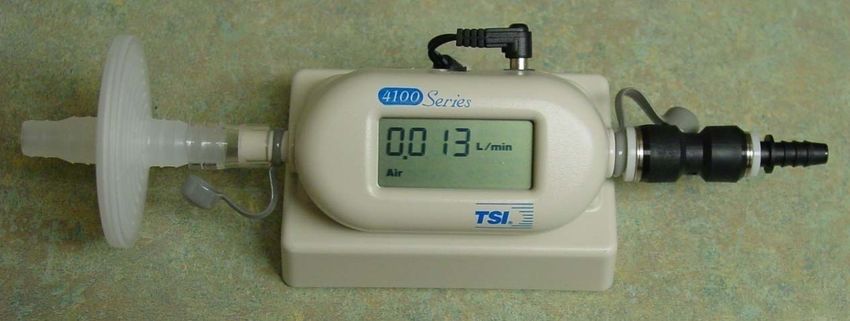
Appendix 4C-3. Sampling Pump Calibration, Electronic, (dry), Bios® DryCal DC-Lite
& Defender™ Airflow Calibrators ........................................................................................ 4C-9
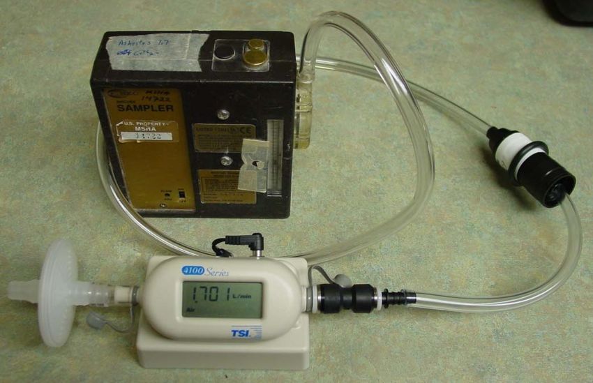
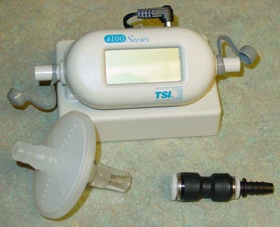
Appendix 4C-4. Sampling Pump Calibration, Electronic, (dry), TSI® 4146
Airflow Calibrator ................................................................................................................ 4C-14
Appendix 4D-1. Calibration Verification Procedures for Wet Method Electronic
Airflow Calibrators (e.g., Sensidyne Gilian) ......................................................................... 4D-1
Appendix 4D-2. Calibration Verification Procedures for Dry Method Electronic
Airflow Calibrators (e.g., TSI, Bios) ..................................................................................... 4D-4
Appendix 4E. Calibration Verification Record .................................................................... 4E-1
Appendix 4F. Leak Check Record, Bios DryCal/Defender .................................................. 4F-1
Figure 4A-1-1. SKC 224-44XR Sampling Pump ................................................................. 4A-1
Figure 4A-1-2. SKC 224-44XR Pump Inlet Filter Housing ................................................. 4A-2
Figure 4A-3-1. SKC AirChek® 2000 Battery Pack Removal Step 1 .................................... 4A-5
Figure 4A-3-2. SKC AirChek 2000 Battery Pack Removal Step 2 ...................................... 4A-5
Figure 4A-3-3. SKC AirChek 2000 Battery Pack Replacement........................................... 4A-6
Figure 4B-1. Burette Set up for Sampling Pump Calibration .............................................. 4B-1
Figure 4C-1-1a. Sensidyne Gilian Gilibrator Set-up for Calibration (respirable dust cassette/
filter and cyclone in-line inside cal jar) ................................................................................. 4C-1
Figure 4C-1-1b. Sensidyne Gilian Gilibrator Set up for Calibration (welding fume MCE
cassette/filter in-line) ............................................................................................................. 4C-1
Figure 4C-1-2. Adding Liquid Soap Solution to the Gilibrator Airflow Calibrator ............. 4C-2
Figure 4C-1-3. Total Dust Cassette In-line ........................................................................... 4C-2
Figure 4C-1-4. MCE Cassette In-line ................................................................................... 4C-2
February 2014 4-2
Metal/Nonmetal Health Inspection Procedures Handbook                                                                              PH06-IV-1(2)

Table of Contents                                                                                                                Page

Figure 4C-1-5. Asbestos Cassette In-line ............................................................................. 4C-3
Figure 4C-1-6. Sorbent Tube In-line .................................................................................... 4C-3
Figure 4C-2-1. mini-BUCK (wet bubble) Sampling Train Calibration Set up..................... 4C-6
Figure 4C-3-1. Bios DryCal DC-Lite (front) ........................................................................ 4C-9
Figure 4C-3-2. Bios DryCal DC-Lite (side) ......................................................................... 4C-9
Figure 4C-3-3. Bios Defender 520...................................................................................... 4C-10
Figure 4C-3-4. Bios Defender 510/SKC Pump with Sorbent Tube Sampling Train
Calibration (in-line) Set up .................................................................................................. 4C-11
Figure 4C-3-5. Bios Defender 510/SKC Pump with Respirable Dust Sampling Train
Calibration Set up ................................................................................................................ 4C-11
Figure 4C-3-6. Total Dust Cassette In-line Calibration Set up for Bios DryCal DC- Lite. 4C-12
Figure 4C-3-7. Respirable Dust Calibration Set up for Bios DryCal DC-Lite ................... 4C-13
Figure 4C-4-1. TSI 4146 Base Underside Showing Airflow Direction Arrow .................. 4C-14
Figure 4C-4-2. TSI 4146 with Filter and Hose Connector ................................................. 4C-14
Figure 4C-4-3. TSI Model 4146 Prepared for Sampling Pump Calibration ....................... 4C-14
Figure 4C-4-4. TSI Model 4146 Set up for Asbestos Sampling Calibration ...................... 4C-15

Figure 4D-1-1.         Sensidyne Factory Calibration Certificate for Gilibrator Flow Cell ............ 4D-2
Figure 4D-2-1.         TSI Airflow Calibrator Calibration Certificate ............................................ 4D-6
Figure 4D-2-2.         Bios Airflow Calibrator Calibration Certificate Example ........................... 4D-7
Figure 4D-2-4.         Bios DryCal DC-Lite Tubing Port Connections .......................................... 4D-9

February 2014                                                 4-3
Metal/Nonmetal Health Inspection Procedures Handbook                                        PH06-IV-1(2)

                                   CHAPTER 4
                      SAMPLING PUMPS & AIRFLOW CALIBRATORS

I.    Introduction

      Metal and Nonmetal uses constant-flow personal sampling pumps to collect several different
      types of occupational exposure samples in conjunction with sampling media, such as; filter
      cassettes, or sorbent tubes (e.g., coconut shell charcoal and high purity washed silica gel). These
      collection media are used when sampling for respirable and total dust, mineral dusts, welding
      fumes and elemental metal dust, asbestos fibers, radon, and organic vapors. To preserve the
      integrity of each sample, the sampling pump must be operating properly. That is, the sampling
      pump must be sufficiently charged, properly maintained, and calibrated with appropriate airflow
      calibrator instrumentation.

II.   Definitions

      Airflow Calibrator: a flow metering device or electronic metering instrument used to calibrate
      or measure the airflow rate created by a sampling pump.

      Bubble Generator: a tube assembly that may be used as an integral part of an air sampling
      pump calibration procedure. When a sampling pump is connected to the bubble generator, the
      vacuum created draws a soap bubble through the device. An electronic sensor automatically
      computes the airflow rate of the sampling pump by calculating the speed of the bubble as it
      travels through the known volume of the calibration tube. It is considered a wet calibration
      method.

      Burette: a cylindrical glass or plastic tube, typically 1.0 - 2.0 liter in volume, which can be used
      to calibrate air sampling pumps and verify airflow meter calibration. With a sampling pump
      connected to the upper end of the burette, the vacuum created draws a soap bubble through the
      burette. A timer is used to measure the period for the soap bubble to travel a specific distance
      through the known volume of the burette. The airflow rate can be calculated from the data
      collected during the timing of several bubbles. It is considered a primary standard of the highest
      quality if the burette is manufactured to class A volumetric glassware standards and is National
      Institute of Standards and Technology (NIST) traceable.

      Calibration: a set of operations, which establish, under specified conditions, the relationship
      between values indicated by a measuring system; i.e., instrument, and the corresponding known
      value of a standard. There are two types of calibration; operational and periodic. Operational
      calibration is carried out routinely as part of instrument usage. The operational calibration
      program involves initial calibration and verification, and continuing calibration checks. Periodic
      calibration is a distinct process with frequency set by manufacturers’ recommendations or by
      enforcement policy requirements.

      Calibration Standard: a reference used to quantify the relationship between the output of an
      instrument and the property to be measured. The parameters of calibration standards should
      bracket the levels for which the actual measurements are to be made. Secondary standards, also
      known as transfer standards, are used for calibration and traceable to a primary standard.

February 2014                              4-4
Metal/Nonmetal Health Inspection Procedures Handbook                                       PH06-IV-1(2)

       Dry Calibrator: a type of airflow calibrator which uses air to set and/or verify flow rate of a
       sampling pump. The electronic instrument automatically computes the airflow rate of the
       sampling pump by calculating the change in volume and movement of the instrument’s piston
       over a given time period.

       Rotameter: a flow metering device consisting of a transparent tube with a small float inside.
       The air flowing through the device causes the float to rise inside the tube to indicate the
       approximate airflow rate. Several sampling pumps currently used by Metal and Nonmetal are
       provided with built in rotameter type flow meters.

       Sampling Pump: a mechanical, battery-operated device that is used to draw air through specific
       collection media (filter or sorbent tube) in order to collect a representative sample of airborne
       contaminant(s) in the mine environment.

       Wet Calibrator: a type of airflow calibrator which uses a soap bubble to set and/or verify flow
       rate of a sampling pump. The electronic instrument automatically computes the airflow rate of
       the sampling pump by calculating the change in volume by measuring the bubble distance
       traveled over time.

III.   General Characteristics

       Metal and Nonmetal uses a variety of personal sampling pumps. Some examples in use are the
       SKC Model 224-44XR (see Figure 4-1) and the Sensidyne Gilian (see Figures 4-2, 4-3).

             Figure 4-1. SKC® Model 224-44XR Sampling Pump.

       The internal components of each sampling pump work on the same basic principles. Sections A
       and B below outline these components and their respective functions.

       Note: Use intrinsically safe MSHA-approved permissible sampling pumps where required in
             gassy mines (e.g., SKC 224-PCXRM, Gilian GilAir).

February 2014                              4-5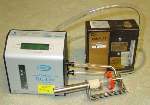
M
Metal/Nonm
         metal Health Inspection
                      I          Procedures
                                 P          Handbook
                                            H                                                    PH066-IV-1(2)

                                         ®
                       Fig
                         gure 4-2. Gilian
                                   G       Mod
                                             del 5000 Sam
                                                        mpling Pum
                                                                 mp.

           Figure
           F                     Air® Plus Sampling Pum
                  4-3. Gilian GilA                    mp (in dock
                                                                king station)).

      A.        Pneumattic System - consists of sixs basic asssemblies: puump/valve, ppulsation
                dampenerr, pressure reegulator, flow
                                                   w indicator, inlet filter, aand baromettric pressure
                compensaation.

                1.      Puump/Valve Assembly
                                       A           - the pump coonsists of duual silicone ddiaphragm pistons
                        drriven by a hig
                                       gh-efficiency DC motorr. The diaphhragm pump is combinedd with
                        loww pressure, positive actiing valves too direct airfloow. The uniit is sealed inn a
                        ho
                         ousing to preevent dirt fro
                                                   om entering. The DC mootor operates from a
                        rechargeable Nickel-Cadm
                                      N            mium (NiCadd), or Nickell-Metal Hyddride (NiMH      H), or
                        Liithium ion, battery
                                      b       pack depending uupon the model.

                2.      Puulsation Dammpener or Damper
                                                   D         Asssembly - connsists of siliicone diaphraagms
                        wiithin the pum
                                      mp stack houusing directlyy above the pump motorr to provide
                        pu
                         ulsation-free flow. Durin ng the intakee stroke, the diaphragmss are stretcheed
                        inw
                          ward by vaccuum. Durin  ng the exhauust stroke, thee diaphragmm elasticity foorces the
                        diaphragms ap part, maintaiining a contiinuous vacuuum on the inntake to the ppump.

F
February 201
           14                                 4-6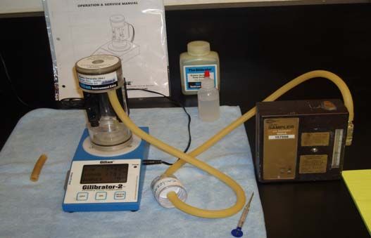
Metal/Nonmetal Health Inspection Procedures Handbook                                      PH06-IV-1(2)
            3.      Pressure Regulator Assembly - used for low flow sampling from 1 to
                    750 milliliters per minute (mL/min). The purpose of the regulator is to maintain
                    suction or discharge at a nominal pressure drop (20.0 to 25.0 inches of water)
                    across the control restrictor. The regulator is not used at flows above 750
                    mL/min. A manual valve is provided on the sampling pump to connect the
                    regulator in and out of the system for low and high flow applications,
                    respectively.

                4.     Flow Indicator - this may be either a digital LCD display on the side of the pump
                       or a rotameter style flow meter mounted vertically inside the case and visible
                       from outside the case through a clear viewing window. Both are useful to
                       confirm continuing operation of the pump. Rotameters are not precision flow
                       meters (± 20 %). Flow readings must be verified with a more accurate calibration
                       instrument.

                5.     Inlet Filter Assembly - consists of a transparent plastic housing and filter
                       membrane held in place with an O-ring. All air drawn into the sampling pump
                       passes through the pump inlet filter. As dust collects on the sampling pump inlet
                       filter over time, the transparent housing permits the operator to view the filter to
                       determine when changing is necessary.

                6.     Barometric pressure compensation - newer pumps have built in capability to
                       correct for changes in altitude between calibration site and sampling site.

       B.       Electrical and Control System - consists of battery pack, control panel, and motor
                control circuitry.

                1.     Battery Pack - the number of cells contained in a battery pack is dependent upon
                       the pump size and permissibility. The battery pack may contain from four to five
                       rechargeable NiCad, NiMH, or Lithium ion cells arranged in series within a
                       plastic housing or “pack” to provide the necessary voltage to the sampler. The
                       battery pack is rechargeable without removal from the sampling pump via an
                       exterior plug-in port.

                2.     Control Panel - consists of either key pads or an on/off switch and recessed flow
                       adjustment control. The flow adjustment control is used to adjust flow rates from
                       0.75 Lpm to 5.0 Lpm (750 mL/min. to 5000 mL/min). Adjustments may be made
                       by either using the up/down arrows on the keypad or turning a small recessed
                       screw clockwise to increase the flow rate, or counterclockwise to decrease the
                       flow rate. A security cover or code protects the control panel from inadvertent
                       adjustment changes when sampling.

                3.     Motor Control Circuitry - comprises a Constant Flow System which provides
                       for constant airflow even though the back pressure of the collecting device may
                       have increased. For example, pressure increase caused by dust accumulation on a
                       filter. As the back pressure increases, the motor voltage is automatically
                       corrected to maintain constant flow.

February 2014                               4-7
Metal/Nonmetal Health Inspection Procedures Handbook PH06-IV-1(2)
IV. Sampling Pump Care and Maintenance
Replacement parts are available from the sampling pump manufacturer. Notify the District
Industrial Hygienist or Health Specialist through your field office supervisor of the items needed.
To maintain the personal sampling pumps in peak operating condition, adhere to the specific
procedures for your respective pump model:
Appendix 4A-1. Sampling Pump Care and Maintenance, SKC 224-44XR, and 224-PCXR4M
Appendix 4A-2. Sampling Pump Care and Maintenance, Gilian 5000 & GilAir Plus
Appendix 4A-3. Sampling Pump Care and Maintenance, SKC AirChek 2000
Appendix 4A-4. Sampling Pump Care and Maintenance, SKC Pocket Pump (low flow)
In general:
Carry sampling pumps in a closed, padded case to avoid damage from impact or
dropping.
When sampling, position the sampling pump in the safest location available on the
person being sampled. Instruct the person not to adjust, turn off, bump, drop, or
otherwise tamper with the sampling pump.
Clean the sampling pump and visually inspect it for defects and damage after each
use or when submitting it for maintenance or calibration.
If the sampling pump fails to function properly during a survey, discontinue the
survey and void the sample. Report the incident to your supervisor. Do not use the
sampling pump again until it is repaired.
V. Sampling Pump Calibration Procedures
A. Background and General Instructions
Whenever constant flow personal air sampling pumps are used to collect a miner’s
exposure using filter cassettes, sorbent tubes, etc, the integrity of each sample must be
preserved and the sampling pump must be operating properly and able to draw a constant
known flow. To ensure this, the sampling pump must be sufficiently charged, properly
maintained, and calibrated with appropriate airflow meter instrumentation and technique.
Calibration procedures, equipment, and location should be in accordance with the
following:
1. Equipment - Metal and Nonmetal uses two types of sampling pump airflow
calibrators: 1.) manual, using a glass burette, and 2.) electronic airflow meters,
using various manufacturers’ instruments. The manual glass burette method is
not usually used in the field setting. Refer to Appendix 4B Sampling Pump
February 2014 4-8Metal/Nonmetal Health Inspection Procedures Handbook PH06-IV-1(2)
Calibration, and Flowmeter Calibration, Manual, 1.0 Liter Burette and Stopwatch,
for using this method.
2. Set up - The airflow calibration instrument used must be assembled with similar
representative media and sampling train included. This procedure is necessary to
simulate the resistance of the media and sampling train to be used during the
sampling. Do not use the calibration media for sampling purposes. When using a
combination cyclone in a calibration jar as shown in Figure 4C-1-1a, the jar must
be air tight. The calibration jar and tubing should be periodically inspected for
leaks, deformed tubing, cracked rubber grommets, etc. If leaks are found, either
replace the defective part(s) or the calibration jar.
3. Location – To replicate atmospheric conditions, calibrate the sampling pump as
near to the sampling site elevation as practical.
4. Frequency - Calibrate a fully charged and stabilized sampling pump before each
full-shift usage.
5. Post-Sampling Calibration Acceptability - Post-sampling calibration checks are
acceptable when the average of consecutive timings agree within ±5% of the pre-
sampling target flow rate. If the post-sampling check does not agree, the sample
is invalid. Post-sampling checks should be conducted as soon as possible after the
sampling shift, preferably within one day of the sampling survey. Do not charge
the pump before conducting post-sampling calibration.
6. Record of Calibration - A written record of sampling pump calibrations and
post-sampling calibration checks must be kept with, or made part of, the
inspection Health Field Notes Form 4000-31A or B.
B. Electronic Calibration Equipment for Air Sampling Pumps
Sampling pump calibration may be accomplished using the glass burette method or an
electronic airflow calibrator instrument. The most convenient and most common
calibrating procedure utilizes electronic flowmeters to adjust (set) the sampling pump
airflow. Metal and Nonmetal uses a variety of electronic airflow meter measurement
devices to calibrate air sampling pumps. To conduct pre- and post- sampling calibration
for your sampling pumps, follow the calibration procedures for the specific Airflow
Calibrator you are using, i.e.:
Appendix 4C-1. Sampling Pump Calibration, Electronic, (wet) Sensidyne® Gilian
Gilibrator™ Airflow Calibrator.
Appendix 4C-2. Sampling Pump Calibration, Electronic, (wet), A.P. Buck®, Inc. mini-
BUCK Calibrator and SKC UltraFlo® Airflow Calibrator.
Appendix 4C-3. Sampling Pump Calibration, Electronic, (dry), Bios® DryCal-Lite and
Defender™ Airflow Calibrator.
February 2014 4-9Metal/Nonmetal Health Inspection Procedures Handbook PH06-IV-1(2)
®
Appendix 4C-4. Sampling Pump Calibration, Electronic, (dry), TSI 4146 Airflow
Calibrator.
VI. Electronic Airflow Calibration Quality Assurance Procedures
The electronic airflow calibrators must be periodically checked against a known accurate
instrument to ensure they are functioning properly. All electronic airflow calibrators used for
calibrating sampling pumps must be included in a quality assurance (QA) program, whereby,
each field airflow calibrator requires an annual check against a laboratory or manufacturer’s
factory calibrated reference instrument. Our primary way to quality assure electronic airflow
calibrator performance is to conduct an annual operational check of field office airflow
calibrators. The airflow calibrator unit must fall within tolerance of the reference volume
measured by a master calibration standard. Each unit must fall within +1% of the reference
volume measured with the certified (NIST traceable) laboratory/factory calibrated master unit.
For example; for a designated master airflow calibrator certified by a manufacturer’s laboratory
at 1.700 Lpm, all other similar type airflow calibrators compared against it must read between
1.717 to 1.683 Lpm. The laboratory data sheet or factory’s certification record for the master
unit and a record of each airflow calibrator’s QA check must be maintained by ID number,
results, and date, for the life of the instrument or a minimum five year history. An example of a
calibration verification record form can be found in Appendix 4E. Electronic airflow calibrators
not meeting the accuracy requirements are sent back to the manufacturer or laboratory/factory
for adjustment/repair and a new calibration certification.
Appendices 4D-1, & 4D-2 provide guidance on calibration verification procedures that can be
used for checking the performance of the field airflow calibrators. For specific QA procedures,
go to:
Wet method (i.e., Gilian) airflow calibrators QA procedures.
See Appendix 4D-1.
Dry method (i.e., Bios, TSI) airflow calibrators QA procedures.
See Appendix 4D-2.
February 2014 4-10Metal/Nonmetal Health Inspection Procedures Handbook PH06-IV-1(2)
Appendix 4A-1
Sampling Pump Care and Maintenance, SKC Models 224-44XR, and 224-PCXR4M
A. Battery Maintenance
1. The SKC models may have NiCad batteries that will develop reduced capacity over time
due to age, long periods of nonuse, or if they are not fully discharged/recharged after
sampling which can result in “memory effect”. This can prevent the sampling pump
from running a long full-shift sampling period in some instances.
2. SKC NiCad (5 cell) batteries are no longer being produced and are being replaced by the
new Nickel-Metal-Hydride (NiMH) battery that does not develop “memory effect”.
Battery maintenance procedures however are still applicable.
3. Use the “PowerFlex” battery charger to automatically perform this function.
4. If you have the “Master Charger” model charger, ensure the discharge button is always
pushed when charging the sampling pump. This will reduce the cause of “memory
effect”.
5. NiMH batteries stored for extended time periods should be recharged every 1-2 months
to avoid complete discharge. The NiMH battery pack has an estimated life of 300–500
charge/discharge cycles, depending on use. The NiCAD battery pack has an estimated
life of 400–600 charge/discharge cycles, depending on use.
B. Changing Battery
1. Removal - Follow the pump manufacturer’s recommendation for removing the battery
pack. In general, remove the screws which secure the battery to the pump. Slide or
remove the battery from the pump. Carefully slide the battery pack out to the right from
under the belt clip, being careful not to cock it at an angle. The edge rails should guide
the pack out.
2. Replacement - Install the new battery making sure the contacts are properly positioned.
Push the battery to the left until it is properly located, reinstall the battery screws and
tighten the case screws. All pump manufacturers recommend the battery pack be fully
charged before installing into the pump. Likewise, the battery pack should be fully
charged before use to ensure maximum longevity and performance.
Figure 4A-1-1. SKC 224-44XR Sampling Pump.
February 2014 4A-1Metal/Nonmetal Health Inspection Procedures Handbook PH06-IV-1(2)
C. Storage
If the sampling pump is stored for long periods (1-6 months), use a cycling charger/ battery
maintenance station (as described in A. Battery Maintenance above) and return sampling pump
to storage.
D. Sampling Pump Inlet Filter
The sampling pump inlet filter, located inside the clear plastic intake port housing, prevents
liquids and/or particulates from being drawn into the pump mechanism. As the filter becomes
dirty or clogged, it can create an excessive load on the sampling pump, decreasing pump
performance. Periodically inspect the sampling pump inlet filter and replace as necessary.
Replace the inlet sampling pump filter and O-ring as follows:
1. Wipe or blow all dust and debris from around the filter housing.
2. Remove the four screws and the front filter housing.
3. Remove the filter membrane and O-ring. Check the O-ring for visible damage and
replace as necessary.
4. Clean the removed filter housing.
5. Insert a new filter membrane (and new O-ring if necessary). Ensure the small center
O-ring is properly seated inside the pump.
6. Reattach the front filter housing and tighten the four screws.
Figure 4A-1-2. SKC 224-44XR Pump Inlet Filter Housing.
For specific and detailed sampling pump instructions refer to the SKC Operation Manuals,
available at www.skcinc.com.
February 2014 4A-2Metal/Nonmetal Health Inspection Procedures Handbook PH06-IV-1(2)
Appendix 4A-2
Sampling Pump Care and Maintenance, Gilian 5000, & GilAir Plus
For specific detailed instruction refer to the Gilian 5000, and GilAir Plus air sampling pump
Operation Manuals, available at www.sensidyne.com
A. Battery Maintenance
1. These pumps use rechargeable Nickel-Metal-Hydride (NiMH) batteries that must be
fully charged before using the pump and properly maintained for maximum run time.
The battery pack requires less than a 4 hour charge from complete discharge.
2. All NiMH batteries lose charge even when not in use. If the battery pack has not been
charged for 3-4 days, recharge battery before use. Use the Fast Charger battery charger
or Five-Unit Power Station to automatically perform this function. This ensures that
batteries are fully charged just prior to sampling. Do not operate the pump during
charging. Charging cycle will begin immediately and will complete as indicated by the
charger LED status.
3. NiMH batteries stored for extended time periods should be recharged every 1-2 months
to avoid complete discharge. The battery pack has an estimated life of 300–500
charge/discharge cycles, depending on use and storage conditions.
B. Changing Battery
1. Removal - Follow the pump manufacturer’s recommendation for removing the battery
pack. Remove the screws which secure the battery to the pump. Then remove the battery
from the pump.
2. Replacement - Install the new battery making sure the contacts and pins are properly
positioned. Pay attention to wire routing so as not to pinch the wires/harness. Replace the
screws and carefully tighten (do not overtighten). Fully charge the battery pack before
use.
C. Storage
Battery life can be extended by storing in cool conditions. High temperatures accelerate aging.
When the sampling pump is stored for long periods (1-6 months), use a cycling charger/power
station, as described in A. Battery Maintenance above, for long term storage.
February 2014 4A-3Metal/Nonmetal Health Inspection Procedures Handbook PH06-IV-1(2)
D. Sampling Pump Inlet Filter
The sampling pump inlet filter, located inside the clear plastic intake port housing, prevents
particulates and/or liquids from being drawn into the pump mechanism. As the filter becomes
dirty or clogged, it can create an excessive flow resistance and increased back pressure, thus
decreasing pump performance. Periodically inspect the sampling pump inlet filter and replace as
necessary.
To replace the sampling pump inlet filter:
Gilian 5000: go to the Maintenance section of the Operation Manual for detailed
instruction. Note that the replacement filter for the Gilian 5000 goes rough side
down.
GilAir Plus: go to the User Maintenance section of the Operation Manual for
detailed instruction. Note the importance of clear and proper gasket and O-ring
positioning when replacing the filter and reassembling the filter housing.
Operation Manuals are available on the internet, at: http://www.sensidyne.com
February 2014 4A-4M
Metal/Nonm
metal Health Inspection
I Procedures
P Handbook
H PH066-IV-1(2)
App
pendix 4A-33
Sampling Pump
p Care and Maintenanc
M ce, SKC AirrChek® 2000
A
A. Batteery Mainten
nance
1. This pump uses eitherr rechargeab ble NiCad orr NiMH batteeries that muust be fully ccharged
before usee as all batteeries lose chaarge when noot in use. Iff the battery pack has nott been
charged for
fo 3-4 days, recharge baattery before use. The baattery pack hhas a charge time of
6 to 8.5 hours based upon
u battery capacity and level of diischarge.
2. Use the “P PowerFlex” battery charrger to autommatically perrform this fuunction. The
“PowerFllex” battery charger
c will automaticallly perform a discharge/rrecharge cyccle on
the NiCad d batteries to
o minimize thhe “memoryy effect”. Thhis ensures thhat batteriess are
fully charrged just prio
or to samplin
ng. The pum mp should noot be used duuring charginng.
3. The manu ual states thaat “After chaarging the baattery pack, iit is good praactice to runn the
pump for approximateely 5 minutees before callibrating. Thhis ensures thhe battery iss in more
steady-staate condition
ns and impro oves the agreeement in pree- and post-ssampling
calibration
ns.” To ensu ure stability, run the pum
mp at least 5 minutes beffore calibratiing.
4. NiMH batteries stored d for extendeed time perioods should bbe rechargedd every 1-2 m
months
to avoid complete
c discharge. Thee NiMH batttery pack hass an estimateed life of 300–500
charge/disscharge cyclles, dependin
ng on use. TThe NiCad bbattery pack has an estim mated life
of 400–6000 charge/discharge cyclles, dependinng on use.
B
B. Chan
nging Batterry
1. Removal - Follow thee pump manu ufacturer’s rrecommendaation for rem
moving the baattery
pack. Rellease the batttery pack by
y removing tthe two secuurity screws located on thhe
bottom off the battery pack. See Figure
F 4A-3--1. Pull the bbattery packk away from the
pump boddy. See Figu ure 4A-3-2.
Figuree 4A-3-1. SK
KC AirChek k 2000 Figuree 4A-3-2. SK
KC AirChek k 2000
Batterry Pack Remmoval Step 1.
1 Batterry Pack Remmoval Step 22.
F
February 201
14 4A-5M
Metal/Nonm
metal Health Inspection
I Procedures
P Handbook
H PH066-IV-1(2)
2. Replacem ment - Carefuully align thee battery jackk on the repllacement batttery pack w
with the
battery terrminal on th
he bottom of the pump baase plate andd push the baattery pack iinto
place. Seee Figure 4AA-3-3.
Fiigure 4A-3-3. SKC AirChek 2000 Battery Pacck Replacem
ment
3. Replace and
a tighten th
he two securrity screws rremoved in S
Step 1. Fullyy charge the battery
pack befo
ore use.
C
C. Stora
age
If thee sampling pump is storeed for long periods
p (1-6 m
months), usee a cycling ccharger/ batteery
mainttenance statiion (as descrribed in Batttery Mainteenance abovve) and returnn to storage..
D
D. Samp
pling Pump
p Inlet Filterr
The sampling
s pummp inlet filteer, located in
nside the cleear plastic inttake port houusing on topp of the
pump p, prevents particulates
p and/or
a liquid
ds from beingg drawn intoo the pump m mechanism. As the
filter becomes dirrty or cloggeed, it can creeate an excesssive load onn the samplinng pump, deecreasing
pump p performancce. Periodiccally inspect the samplinng pump inleet filter and O O-ring and reeplace as
necesssary. Replaace the inlet sampling pu ump filter annd O-ring as follows:
1. Remove the
t three screews that secu
ure the inlet port housinng to the top of the pumpp.
2. Remove the
t inlet portt housing and gasket. Caarefully rem
move the O-riing.
3. Remove and
a discard the
t filter. In
nsert the new
w filter.
4. Insert O-rring.
5. Replace th
he gasket.
6. Align the inlet port ho
ousing with the three scrrew holes annd the LED.
F
February 201
14 4A-6Metal/Nonmetal Health Inspection Procedures Handbook PH06-IV-1(2)
Appendix 4A-4
Sampling Pump Care and Maintenance, SKC Pocket Pump® (low flow)
Note: These pumps are used for specialized purposes and unique processes.
A. Battery Maintenance
1. This pump uses either rechargeable NiCad or NiMH batteries that must be fully charged
before use as all batteries lose charge when not in use. Newer pumps use the NiMH
battery, however while the NiCad batteries are found in the older models, NiMH batteries
can be retrofitted in them.
2. Important note for this pump. New battery packs MUST be completely charged
BEFORE installing them into the pump. This initial slow (16-hour) charge will provide
optimum battery performance. After completely charging, then install the new battery
pack into the pump.
3. Once the new battery has been charged and installed in the pump, plug the charger into a
standard wall outlet and the charging plug into the battery port on the bottom of the
pump. The fast charging function of the battery pack will completely recharge the
battery in approximately 6 hours or less. The pump should not be running during
charging.
4. NiMH batteries stored for extended time periods should be recharged every 1-2 months
to avoid complete discharge. The NiMH battery pack has an estimated life of 300–500
charge/discharge cycles, depending on use. The NiCad battery pack has an estimated life
of 400–600 charge/discharge cycles, depending on use.
B. Changing Battery
1. Removal - Follow the pump manufacturer’s recommendation for removing the battery
pack. Begin by pressing down on the sliding keypad cover near the SKC logo. Push the
keypad cover down and away from the display until it is free from the pump case.
2. Lay the pump on a flat surface with the LCD facing upward. Remove the two screws on
the front panel of the pump.
3. Turn the pump over so that the LCD faces down. Remove the belt clip by unscrewing the
single locking screw, and remove the battery compartment cover.
4. Remove the old battery pack by carefully lifting it upward and from the pump.
5. Align the jack on the new fully charged replacement battery pack with the pins on the
pump. Press into place. Replace the battery compartment cover and belt clip removed in
Step 3.
6. Turn the pump over so that the LCD faces upward. Replace the two screws on the front
panel of the pump (do not overtighten the screws). Replace the keypad cover by
aligning it with the ridges on each side of the keypad, pressing it down, and pushing it
upward.
February 2014 4A-7Metal/Nonmetal Health Inspection Procedures Handbook PH06-IV-1(2)
C. Storage
When the sampling pump is stored for long periods (1-6 months), use a cycling charger/power
station, as described in Battery Maintenance above, for long term storage.
D. Sampling Pump Inlet Filter
The sampling pump inlet filter, located inside the plastic intake port housing on top of the pump,
prevents particulates and liquids from being drawn into the pump mechanism. As the filter
becomes dirty or clogged, it can create an excessive load on the sampling pump, decreasing
pump performance. Periodically inspect the sampling pump inlet filter and replace as necessary.
February 2014 4A-8M
Metal/Nonm
metal Health Inspection
I Procedures
P Handbook
H PH066-IV-1(2)
Ap
ppendix 4B
Sampling Pump
P Calib
bration and Airflow Caalibrator Caalibration, M
Manual,
1.0 Liter Burrette and Sttopwatch
This method is thhe simplest and
a least exp pensive to caalibrate samppling pumps, and qualityy assure
airflo
ow calibratorr performancce. However, the proceddure is laborr intensive, thhe equipmennt is
cumb bersome to trransport in th
he field, and
d the glass buurette is fraggile.
A
A. Pre-iinspection Calibration
C
1. Assemblee using the diagram
d in Fiigure 4B-1:
• Assemmble the tripood stand by sscrewing thee legs into thhe sockets inn the
tripod base. Attach the supporrt rod and claamp to the bbase. Place tthe
tripod//support rod assembly uppright on a level surfacee.
• Wet thhe entire inside surface oof a 1.0 liter glass burettee by pouringg water
througgh it or holdinng under a ffaucet. Inserrt the burettee into the trippod base
right siide up, until it is severall inches abovve the level ssurface.
2. Connect the
t apparatuss to the samp
pling pump w
with an asseembled samppling train inn line.
3. Check thee seals on alll hose conneections. Thee entire systeem must be lleak-free.
Figure 4B-1.
4 Burettte Set up forr Sampling Pump Caliibration.
4. Turn the sampling
s pu
ump on; let itt run for 10 m
minutes to sttabilize flow
w.
5. Raise the beaker conttaining the so
oap solutionn and momenntarily submerge the opeening of
the burettte.
F
February 201
14 4B-1Metal/Nonmetal Health Inspection Procedures Handbook PH06-IV-1(2)
• Raise the beaker to form one bubble at a time.
• Repeat several times until a bubble travels the entire distance up the
burette without breaking.
6. Using a stopwatch, time the travel of the bubble from the ‘zero’ line (0.0 liter) to the 1.0
liter mark.
• Travel times for common flow rates are:
Flow Rate Time
1.4 Lpm 42.9 sec.
1.7 Lpm 35.3 sec.
2.0 Lpm 30.0 sec.
• For other flow rates, use the formula below to calculate the time required
for the bubble to travel the length of the burette:
1.0 liter = time (min.)
Desired flow rate (Lpm)
[time in min. X 60 sec./min. = time in sec.]
7. The sampling pump must be within 5 % of the target flow rate. For example, the
acceptable range of 1.7 liters per minute (Lpm) (±5 %) is 1.615 Lpm to 1.785 Lpm. This
is the same as the bubble passing the 1.0 liter length of the burette between 33.7 and 37.0
seconds. Adjust the sampling pump flow rate as described in the operating instructions
for the individual pump. When the measured flow rate is within the acceptable ± 5 %
range, take three more readings for each sampling pump and average.
8. Record the following in the Health Field Notes:
• Sampling pump ID number;
• Calibrated flow rate (average of three readings);
• Date and location of calibration; and
• Name of person performing calibration.
B. Post-inspection Calibration
1. Repeat Steps A. 1. through A. 8. above (see V. A. 5.).
2. If more than a few days will elapse before doing further calibrations, remove the burette
from the tripod stand and rinse the inner surface of the burette thoroughly with tap water
to avoid buildup of soap residue.
February 2014 4B-2Metal/Nonmetal Health Inspection Procedures Handbook PH06-IV-1(2)
Appendix 4C-1
Sampling Pump Calibration, Electronic, (wet), Sensidyne® Gilian Gilibrator™ Airflow Calibrator
Similar in principal to the burette, this method generates a series of soap bubbles through a tube
connected to the air sampling pump. However, the time for the bubble to rise the length of the
tube is measured automatically and the flow rate is subsequently calculated by a computer chip
in the airflow calibrator’s base. While the equipment is more expensive than that used in the
burette method, it is much more portable than the cumbersome burette and less time consuming
in setup. [For detailed instructions please refer to the Gilibrator manual, available at:
www.sensidyne.com].
A. Pre-Inspection Calibration. Refer to Figure 4C-1-1a., b. and follow these steps:
Figure 4C-1-1a. Sensidyne Gilian Gilibrator
Set up for Calibration (respirable dust
cassette/filter and cyclone in-line inside cal jar)
Figure 4C-1-1b. Sensidyne Gilian Gilibrator
Set up for Calibration (welding fume MCE
cassette/filter in-line)
February 2014 4C-1Metal/Nonmetal Health Inspection Procedures Handbook PH06-IV-1(2)
1. It takes at least 14 hours to fully charge a calibrator; the device can be used while
charging.
2. Grasp the lower portion of the flow cell and attach it to the base by placing it upright on
the control unit mounting plate. While grasping only the flow cell base, gently rotate it
until it “clicks” into place and the electrical socket on the side is facing toward the rear of
the base.
3. Insert the control unit’s cable assembly into the sensor block connecting jack located on
the back of the sensor block.
4. Remove the storage tubing from the air outlet boss of the flow cell. Using the rubber
storage tubing as a funnel, slowly add soap solution from the dispenser. The amount of
soap needed is determined by depressing the bubble initiate button and holding it down in
the lower position. Continue to add enough soap solution until the angled edge at the
bottom of the bubble generator ring is immersed in the solution (see Figure 4C-1-2.).
Figure 4C-1-2. Adding Liquid Soap Solution to the Gilibrator Airflow Calibrator.
5. Connect the sampling pump (with the sampling train in line) to the upper outlet boss.
Figure 4C-1-3. Total Dust Cassette Figure 4C-1-4. MCE Cassette
In-line. In-line.
February 2014 4C-2Metal/Nonmetal Health Inspection Procedures Handbook PH06-IV-1(2)
Figure 4C-1-5. Asbestos Cassette In-line.
Figure 4C-1-6. Sorbent Tube In-line.
6. Turn on the sampling pump; let it run 10 minutes to stabilize.
7. Prime (wet) the inner walls of the flow tube by depressing the bubble initiator button
several times.
8. Turn on the calibrator power switch and wait while the system runs through its self-check
sequence. The calibrator is not ready until the Flow, Average, and Sample # are shown
in the LCD panel of the Gilibrator.
9. Generate a bubble, and read the flow rate that appears on the LCD display. The actual
flow for each bubble will be displayed. The flows will accumulate and be averaged with
each successive pressing of the bubble generator.
Note: Each time the button is pushed, the display will show the flow rate in cubic
centimeters per minute (ccm), which is the same as milliliters per minute
(mL/min). Convert these values to liters per minute (Lpm) by dividing the
number by 1000 (or moving the decimal point three places to the left).
If a bubble breaks before the time sequence is completed, timing will continue
until another bubble is generated. The subsequent bubble will cause an erroneous
reading. To subtract the erroneous reading from the average, push the DEL
(delete) button.
a. Deleting readings:
To delete obvious false readings, push the DEL button. This will automatically
delete the false information from the average and reset the average and sample
number back to the previous reading.
February 2014 4C-3Metal/Nonmetal Health Inspection Procedures Handbook PH06-IV-1(2)
b. Resetting:
To reinitiate the sequence for additional sampling pump calibrations, push
the RESET button. This zeroes out all samples and average registers
within the unit and starts a new sequence.
The RESET button is also used if a malformed bubble is generated and
has not been subtracted from the average by use of the DEL button.
10. The sampling pump must be within ± 5 % of the target flow rate. For example, the
acceptable range of 1.7 liters per minute (± 5 %) is 1.615 Lpm to 1.785 Lpm. Adjust the
sampling pump flow rate by turning the flow adjustment set screw with a screwdriver or
using the up/down arrow buttons, depending upon pump model. When the measured
flow rate is within the acceptable ± 5 % range, press and hold the reset button on the base
until all readings are “0.” Then take 3 more readings.
11. Record the following in the Health Field Notes:
Sampling pump ID number;
Calibrated flow rate (average of three readings);
Date and location of calibration; and
Name of person performing calibration.
B. Post-Inspection Calibration
1. Repeat Steps A.1. through A.11. above.
2. Sampling is valid when the post- and pre-sampling flow rates agree within ± 5 % of the
target flow rate for three (3) consecutive timings. Otherwise, the sample is invalid.
3. This post-sampling calibration check may be used as the pre-sampling calibration flow-
rate for the next full-shift sample if the sampling pump is used within a week.
C. Maintenance and Calibration
1. Between uses and if the calibrator is not to be used for a period of time, reinstall the
rubber storage tubing between the inlet and outlet bosses. This will prevent evaporation
which may alter the soap solution’s concentration. If more than several days will elapse
before doing further calibrations, remove the bubble generator from the base. Rinse the
inside of the bubble generator thoroughly with water to avoid buildup of soap residue.
The easiest way to rinse the bubble generator is to fasten a short piece of rubber hose to
the bottom nipple of the bubble generator, place the open end of the hose under the tap,
and let the water run freely through the hose, into the generator, and out the top nipple.
Remove excess water by turning the bubble generator alternately upside down and right
side up and gently shaking it. Allow the cylinder to dry thoroughly before using or
placing it in the storage case. Do not disassemble and clean the inside of the bubble
generator.
February 2014 4C-4Metal/Nonmetal Health Inspection Procedures Handbook PH06-IV-1(2)
2. “Low Battery” will appear on the display if the battery voltage is too low to operate the
unit properly on battery power alone. The battery charges automatically when the
charger unit is plugged into an electrical outlet and the charger unit cord is plugged into
the Gilibrator base. The charger also serves as an AC adapter. An indicator light, glows
red when charging is taking place.
3. Do not transport the unit with soap solution or storage tubing in place. When transporting
or shipping the electronic calibrator by air, it is important to remove one side of the
storage tube that connects the inlet and outlet bosses. This allows for equalizing internal
pressure within the generator.
Caution: Do not pressurize the flow cell. Excessive pressure may cause the cell to
rupture.
4. Each Sensidyne Gilian Gilibrator used in the field requires at least an annual check
against a laboratory or factory calibrated instrument. The annual check of each field
office Gilibrator must fall within a +1% tolerance of the volume measured with the
laboratory/factory certified master Gilibrator airflow calibrator (see also Appendix 4D-1).
Or, the matched set is sent as a unit to the laboratory/factory for testing and certification.
There is no other regular maintenance required by the user. If the unit requires repair
(including replacement of the rechargeable NiCad battery) coordinate repairs through the
District Health Specialist or Industrial Hygienist.
February 2014 4C-5Metal/Nonmetal Health Inspection Procedures Handbook PH06-IV-1(2)
Appendix 4C-2
Sampling Pump Calibration, Electronic, (wet), A.P. Buck®, Inc. mini-BUCK™ Calibrator and
SKC UltraFlo® AirFlow Calibrators
Like the Gilibrator, these devices connect to an air sampling pump and generate a series of soap
bubbles through a tube (i.e., wet method). The bubble rise rate is measured electronically and
the flow rate is automatically calculated by an internal computer chip.
A. Pre-inspection Calibration. Refer to Figure 4C-2-1.
1. Using the squeeze bottle included, pour enough soap solution through the bottom nipple
(at the rear of the transparent tube assembly) to cover the bottom of the flow cell (bubble
generator). The level of the solution should not be higher than the etched line.
2. Fasten a piece of rubber or Tygon® hose (several inches in length) to the upper (not the
filler) nipple. Fasten a filter cassette (of the same type to be used in sampling) onto the
loose end of the rubber or Tygon hose. The inlet side should face toward the nipple.
3. Fasten a second piece of hose between the air sampling pump and the filter. Do not
connect the filter to the mini-BUCK’s filler nipple.
4. Turn on the fully charged air sampling pump and run it for approximately 10 minutes to
ensure the voltage (and flow rate) has stabilized. Wet the inside of the flow cell by
rapidly pressing and releasing the spring-loaded button (front of the transparent tube
assembly) until complete bubbles rise all the way to the top of the tube. At the same
time, push the mini-BUCK “on” switch. The Calibrator will display “0000.” If the
Calibrator does not turn on, it may be operated on AC current by plugging it into its
charger unit and plugging the charger unit into an electrical outlet.
Figure 4C-2-1. mini-BUCK (wet bubble) Sampling Train Calibration Set up.
February 2014 4C-6Metal/Nonmetal Health Inspection Procedures Handbook PH06-IV-1(2)
5. Firmly press and release the button on the base of the transparent flow cell. A number
will flash in the mini-BUCK display. Wait until the number stops flashing, and then
repeat twice until one or more bubbles rise all the way to the top of the bubble generator
and the reading is stable. Each time the button is pushed, the display will show the flow
rate in milliliters per minute (mL/min.). Convert these values to liters per minute (Lpm)
by dividing the number by 1000 (or moving the decimal point three places to the left).
6. The sampling pump must be within ± 5 % of the target flow rate. For example, the
acceptable range of 1.7 Lpm (± 5 %) is 1.615 to 1.785 Lpm. Adjust the sampling pump
flow rate as described in the operating instructions for the pump. When the measured
flow rate, is within the acceptable ± 5% range, press and hold the “on” button of the
mini-BUCK until “0000" is displayed; then take three more readings (waiting for the
flashing to stop between each press of the button).
7. Record the following in the Health Field Notes:
Sampling pump ID number;
Calibrated flow rate (average of three readings);
Date and location of calibration; and
Name of person performing calibration.
B. Post-Inspection Calibration
1. Repeat steps A. 1. through A. 7. above.
2. Sampling is valid when the post- and pre-sampling flow rates agree within ± 5 % of the
target flow rate for three (3) consecutive timings. Otherwise, the sample is invalid.
3. This post-sampling calibration check may be used as the pre-sampling calibration flow-
rate for the next full-shift sample if the sampling pump is charged and used within a
week.
4. After post-calibrating all sampling pumps, press the “off” button, disconnect the rubber
hoses and plug both nipples (usually with a short piece of rubber tubing that connects the
two nipples) to keep the flow cell from drying out. If more than several days will elapse
before doing further calibrations, remove the flow cell from the base by unscrewing the
three screws on the underside of the base. Rinse the inside of the flow cell thoroughly
with tap water to avoid buildup of soap residue. Fasten a short piece of rubber hose to
the bottom nipple, place the open end of the hose under the tap, and let the tap water run
gently but freely through the hose, into the flow cell, and out the top nipple. Remove
excess water by turning the flow cell alternately upside down and right side up and gently
shaking it. Dry the outside of the flow cell with a soft paper or cloth towel and reinstall
in the mini-BUCK base by replacing the three screws. Allow the inside to air dry; do not
attempt to disassemble and clean the inside of the flow cell.
Note: The mini-BUCK automatically shuts-off after seven minutes of non-use.
February 2014 4C-7Metal/Nonmetal Health Inspection Procedures Handbook PH06-IV-1(2)
C. Battery Charging and Replacement
1. The battery charges automatically when the charger unit is plugged into an electrical
outlet and the charger unit cord is plugged into the mini-BUCK base. The charger also
serves as an AC adapter. Do not leave the AC adapter plugged in when not in use, as this
could damage the battery supply.
2. The fully charged battery will operate the unit for up to 8 hours. Low Battery light will
appear on the faceplate of the mini-BUCK if the battery voltage is too low to operate the
unit properly. The mini-BUCK requires 16 hours to charge the battery fully.
D. Maintenance and Calibration
Each field mini-BUCK Calibrator requires an annual check against a laboratory/factory
calibrated instrument. The annual check of the mini-BUCK calibrator against the
laboratory/factory master calibrated instrument must fall within a 1% tolerance of the referenced
volume. Or, the unit itself can be sent to the laboratory/factory for testing and certification. No
maintenance is performed by the user. If the unit requires repair (including replacement of the
rechargeable NiCad battery) coordinate repairs through the District Health Specialist or
Industrial Hygienist. Always clean the unit and leave the filler nipples open and disconnected
from any tubing when instrument is being shipped.
February 2014 4C-8Metal/Nonmetal Health Inspection Procedures Handbook PH06-IV-1(2)
Appendix 4C-3
Sampling Pump Calibration, Electronic, (dry), Bios® DryCal DC-Lite and Defender™
Airflow Calibrators
Both the Bios DryCal DC-Lite and Defender do not use liquids or generate bubbles and
are another type of field-portable flow calibrators for industrial hygiene airflow
measurement applications (i.e., dry method). Both of these Bios airflow meters (and the
only airflow calibrators) do not use the jar for calibrating sampling trains. The units use
a near-frictionless dry piston technology that can be conveniently used in the field.
A. Bios DryCal DC-Lite
1. Press the On button to turn the DryCal DC-Lite on. An initializing screen will display
the microprocessor revision number and then the standard screen will be displayed.
Note: The DryCal DC-Lite has an energy saving auto shut-off feature. After 5-minutes
of non-use the unit will automatically shut itself off.
Inlet
Outlet
Figure
Figure4-C-3-1.
4C-3-1. Bios
BiosDryCal-Lite.
DryCal DC-Lite Figure 4C-3-2. Bios DryCal DC-Lite
(front). (side).
2. The DryCal DC-Lite’s inlet and outlet ports are located on the right side of the unit.
Connect the tubing from the sample pump including the in-line calibration media (e.g.,
asbestos, sorbent tube, total dust, welding fume cassette) to the Outlet (bottom) port. See
Figure 4-C-3-6.
NOTE: For respirable dust sampling pump calibration, the dust/cassette including the
cyclone and holder are not in-line. Connect the sampling pump tubing to the Outlet
(bottom) port and the respirable dust sampling assembly on a short 2.5 inch tubing to the
Inlet (top) port. See Figure 4-C-3-7. Do not re-use calibration media assemblies for
sampling.
3. Press and release the Read button on top of the unit to take a single reading. Pressing the
Read button again will cause the unit to take another reading. After the first single
reading, all subsequent readings will be used to calculate the average flow. After 10
readings, the average will be cleared to begin a new averaging sequence. You will know
a reading has begun when the valve “clicks” shut, the flow cell’s green LED lights are on,
and the piston rises within the flow cell.
February 2014 4C-9You can also read