Comfort air curtain Manual

Page created by Neil Medina
 
CONTINUE READING
Comfort air curtain Manual
Manual
Comfort air curtain
Model CA2

Version 7.0
Original Manual       English

a
Comfort air curtain Manual
en
                                                                        COMFORT AIR CURTAIN

      . . . Contents

     1      Introduction                                                                 4
             1.1   About this manual                                                     4
             1.2   How to read this manual                                               4
             1.3   About the unit                                                        5
             1.4   Safety instructions                                                  11

     2      Installation                                                               13
             2.1   Safety instructions                                                  13
             2.2   Delivery check                                                       13
             2.3   General working method                                               13
             2.4   Suspending the unit                                                  15
             2.5   Connecting the unit to the central heating system                    18
             2.6   Connecting the unit to the Daikin system                             20
             2.7   Connecting the unit to the power supply                              22
             2.8   Installing the control panel and external controls                   25
             2.9   Unit finishing                                                       33
            2.10   Powering up and testing                                              38

     3      Operation                                                                  40
             3.1   Introduction                                                         40
             3.2   Switching ON and OFF                                                 41
             3.3   The Home screen                                                      41
             3.4   CHIPS control                                                        41
             3.5   Adjusting the strength of the air curtain                            42
             3.6   Controlling the temperature                                          43
             3.7   Faults                                                               43
             3.8   Main menu                                                            43
             3.9   Preferences                                                          45
            3.10   Settings                                                             46
            3.11   Configuration                                                        47
            3.12   Maintenance                                                          51
            3.13   USB                                                                  53

     4      Maintenance                                                                55
             4.1   Replacing or cleaning the filter                                     55
             4.2   Cleaning the unit                                                    57
             4.3   Scheduled maintenance                                                57

     5      Faults                                                                     58
             5.1   Safety instructions                                                  58
             5.2   Resolving simple problems                                            58
             5.3   Fault messages on the control panel                                  60
             5.4   Remedying faults accompanied by an error message                     61
             5.5   Remedying faults without message                                     66

     en-2                                                                            B
Comfort air curtain Manual
en
CA2 MANUAL

6             Service                                                      68
               6.1    Safety instructions                                   68
               6.2    Access to the interior of the unit                    68
               6.3    Electronics module                                    70
               6.4    Daikin electronics                                    71
               6.5    Fuses                                                 71
               6.6    Removing the discharge section                        72
               6.7    Venting the heat exchanger                            72
               6.8    Bleeding the heat exchanger                           73
               6.9    Entering the unit code                                73
              6.10    Resetting the PIN code                                74
              6.11    Updating the software of the b-touch control panel    75
              6.12    Replacing the battery of the wireless sensors         76
              6.13    Biddle control cable composition                      77

7             Dismantling                                                  78

Manual version 7.0 (22-04-2013)                                            en-3
Comfort air curtain Manual
en

     1. .         Introduction

     1.1    About this manual
                                      This manual describes the installation, operation and mainte-
                                      nance of the Comfort air curtain model CA2 with b-touch con-
                                      trol panel and CHIPS control. The manual also provides
                                      instructions and information on service operations.

     1.2    How to read this manual

                                      1.2.1 Daikin manuals

                                      Only for CA2V and CA2Q:

                                      This manual makes cross-reference to the manuals of the Dai-
                                      kin components (outdoor unit, indoor unit, control panel,
                                      etc.).

                                      1.2.2 Marginal symbols used in the manual

                                      The following symbols are used in this manual:

                                               Note:
                                      n        Draws your attention to an important part of the
                                               text.

                                               Caution:
                                      c        If you do not perform this procedure or action
                                               correctly, you may damage the device.

                                               Follow the instructions strictly.

                                               Warning:
                                      w        If you do not perform this procedure or
                                               action correctly, you may cause damage and/
                                               or bodily injury.

                                               Follow the instructions strictly.

     en-4
en
CA2 MANUAL                                                                                            INTRODUCTION

                                                                Danger:
                                                      d         This indicates actions which are not
                                                                permitted.

                                                                Ignoring this warning may lead to serious
                                                                damage or accidents which may involve bodily
                                                                injury.

                                                      1.2.3 Pictograms used on the unit and in the manual

                                                      The following pictograms indicate potential risks or hazards.
                                                      The same pictograms will also be found on the unit.

Pictograms

 PICTOGRAM           DESCRIPTION

                   w         You are entering an area of the unit containing live components.

                             Accessible to qualified maintenance staff only.

                             Exercise caution.

                   w         This surface or part can be hot. There is a risk of burns on contact.

                                                      1.2.4 Related documentation

                                                      Besides this manual, the following documents have been sup-
                                                      plied with the unit:

                                                      •   Installation and servicing wiring diagram

1.3        About the unit

                                                      1.3.1 Applications

                                                      General

                                                      The purpose of the Comfort air curtain is to separate cli-
                                                      mates between two rooms and to heat and filter (filter class
                                                      EN779-G2) air. The unit is installed above the doorway, across
                                                      its full width.

Manual version 7.0 (15-05-2013)                                                                                  en-5
en
     INTRODUCTION                                               COMFORT AIR CURTAIN

                    Mounting methods

                    The free-hanging model is designed for free, visible installation
                    above the door.

                    The recessed model is designed for installation into a false
                    ceiling or into an alcove where the air inlet may be at some
                    distance from the unit itself.

                    The cassette model is designed for installation above a false
                    ceiling where the air inlet is close to the unit and the unit is
                    easily accessible.

                    Comfort air curtain for Daikin system

                    On models CA2V and CA2Q:

                    The air connection is connected to a Daikin direct expansion
                    system. The air blown through the unit is heated by the cool-
                    ing medium. The air curtain is controlled and operated partly
                    by the Daikin system and partly by the Biddle system.

                    The system has a number of limitations:

                    •   The unit is only suitable for use in Daikin direct expansion
                        systems.
                    •   The unit is not suitable for cooling.
                    •   The Daikin system has to be active at all times.

                    Other versions and intended usage.

                    On request, versions can be supplied for other applications.

     en-6
en
CA2 MANUAL                                                                        INTRODUCTION

                                            Warning:
                                  w         Applications other than those described
                                            above are not considered to be an intended
                                            use. Biddle assumes no responsibility for
                                            damage or injury resulting from applications
                                            other than the intended use. The intended
                                            use also implies observance of and
                                            compliance with the instructions in this
                                            manual.

                                  1.3.2 Mode of operation

                                  The air curtain blows out a warm air stream straight down,
                                  thus achieving the following:

                                  •   The exchange of air between two rooms due to tempera-
                                      ture differences (convection) is stopped.
                                  •   The cold air entering across the floor due to draught is
                                      heated.

                                  Depending on the air curtain's setting, the unit can also blow
                                  unheated air.

                                  1.3.3 About the automatic CHIPS control

                                  The CHIPS control matches the strength and heat of the air
                                  curtain to changing weather conditions. This reduces energy
                                  consumption and improves comfort through selection of the
                                  optimum setting under all circumstances. CHIPS stands for
                                  “Corrective Heat and Impulse Prediction System”.

                                  The operation of the air curtain is based on the outside tem-
                                  perature and the room temperature near the air curtain.

                                  1.3.4 Type designation

                                  The table below provides an overview of available models of
                                  the Comfort Air Curtain and the corresponding type designa-
                                  tions. In combination, the type designations constitute the
                                  type code, for instance: CA S-100-W-F.

                                  If some part of the manual applies to certain models only,
                                  these will be indicated using the corresponding type designa-
                                  tion, for example:

                                  •   S: Models with capacity S
                                  •   100: Models with discharge width 100
                                  •   W: Water-heated models

Manual version 7.0 (15-05-2013)                                                              en-7
en
     INTRODUCTION                                                                               COMFORT AIR CURTAIN

                                                    •    E: Electrically-heated models
                                                    •    F: Free-hanging models

                                                                Note:
                                                    n           In the illustrations in this manual, the following unit
                                                                type is used as a general example: CA M-150-W-F.
                                                                The appearance of your unit may be different but its
                                                                function is the same, unless stated otherwise.

     Explanation of the type code

      PART TYPE CODE         DESIGNATION                MEANING
      Product series         CA2                        General reference for the series
                             CA2V                       For connection to Daikin VRV system (‘multi’)
                             CA2Q                       For connection to Daikin ERQ system (‘pair’)
      Capacity               S                          short range
                             M                          medium range
                             L                          long range
                             XL                         extra-long range
      Discharge width        100, 150, 200 or 250       Discharge width in cm
      Heating                W                          Water heating
                             E                          Electric heating
                             A                          Without heating
                             DK                         Heating with Daikin direct expansion system
      Mounting method        F                          Free-hanging model
                             R                          Recessed model
                             C                          Cassette model
      Only models for Dai-   B                          White
      kin system:            S                          Aluminium
      Colour                 X                          Non-standard colour
      Only models for Dai-   C                          Biddle control panel included
      kin system:            N                          Not supplied
      Control panel

     en-8
en
CA2 MANUAL                                                                                        INTRODUCTION

                                              1.3.5 Type plate

Example of a type plate                       The type plate is located on the left at the front of the unit.

                                              This manual refers to the following data on the type plate:

                                              •     Type: Complete type code of the unit;
                                              •     M: Weight of the unit
                                              •     Medium: Heating medium
                                              •     Capacity Index: Daikin capacity index
                                              •     Pmax: Maximum permissible working pressure in the hot
                                                    water circuit (at 110°C).
                                              •     U, Imax, Pmotor en Pheating: Maximum load on the electrical
                                                    system by the unit.

                                              1.3.6 Field of application

                                              The Comfort Air Curtain is predominantly used in commer-
                                              cial premises at an ambient temperature of max. 40°C. The
                                              following parameters must be observed:

Parameters of use for all models

 Ambient temperature                        5 °C to 40 °C
 Connection voltage                         see type plate
 Power                                      see type plate
 Maximum discharge temperature              50 °C

Parameters of use for water-heated models

 Heating medium                             water with max. 20% glycol
 Maximum working pressure and temperature   6 bar at 110 °C
 Maximum valve pressure difference:
 - type S/M                                 0.5 bar
 - type L/XL                                1.0 bar

                                                          Warning:
                                              w           The air curtain must not be employed in
                                                          potentially explosive atmospheres, wet
                                                          environments, outdoors or in very dusty or
                                                          aggressive air.

                                                          Biddle assumes no responsibility for damage
                                                          or injury resulting from use in these
                                                          situations.

Manual version 7.0 (15-05-2013)                                                                              en-9
en
     INTRODUCTION                                             COMFORT AIR CURTAIN

                    1.3.7 Modifications and changes

                    No changes or modifications may be made to the unit which
                    could influence its safety without the approval of Biddle. The
                    CE mark is no longer valid if the unit has been modified or
                    changed in any way.

                    1.3.8 Components and accessories

                              Note:
                    n         The type code of components and accessories must
                              correspond to that of the unit with which they will
                              be employed.

                    Accessories for operation and control

                    The following components are delivered separately but always
                    required:

                    •   b-touch control panel (able to control a maximum of 10
                        units)
                    •   outdoor sensor
                    •   Door contact switch
                    •   Biddle control cable, available in various lengths

                    Accessories

                    The following accessories are available as options

                    •   Wireless temperature sensor set instead of the standard
                        outdoor sensor
                    •   Wireless indoor temperature sensor
                    •   Tendency sensor instead of an outdoor temperature sen-
                        sor
                    •   Filter sensor (pressure sensor) in the unit to measure fil-
                        ter contamination
                    •   Infrared sensor in the unit to count passages instead of the
                        standard door contact switch
                    •   BEM communication module for Modbus and RS232 com-
                        munication, instead of the b-touch control panel

     en-10
en
CA2 MANUAL                                                                           INTRODUCTION

                                  Accessories for attachment and finishing

                                  The following components are delivered separately but always
                                  required:

                                  •   For free-hanging models only:
                                      set of end caps

                                  The following accessories are available as options:

                                  •   Set of wall consoles, ‘Standard’ or ‘Design’
                                  •   Threaded rod lining

                                  Daikin components

                                  The following Daikin components are required for models that
                                  are to be connected to a Daikin direct expansion system:

                                  •   Outdoor unit
                                  •   optional, only possible with a VRV system:
                                      one or more indoor units
                                  •   Daikin control panel
                                  •   Connection materials, such as cooling lines, wiring, etc.:
                                      see the Installation Manual for the outdoor unit

                                            Caution:
                                  c         The control system and capacity index of the Daikin
                                            outdoor unit must correspond to those of the
                                            Biddle air curtain.

1.4        Safety instructions

                                  1.4.1 Safety in use

                                            Warning:
                                  w         Do not put any objects in the inlets and
                                            outlets.

                                            Warning:
                                  w         Do not obstruct the unit’s inlets or outlets.

                                            Warning:
                                  w         The upper surface of the unit becomes hot
                                            during operation.

Manual version 7.0 (15-05-2013)                                                               en-11
en
     INTRODUCTION                                            COMFORT AIR CURTAIN

                              Caution:
                    c         In exceptional situations, water may run out of the
                              unit. Therefore do not place anything under the unit
                              that could be damaged as a result.

                    1.4.2 Safety issues relating to installation, mainte-
                          nance and servicing

                              Danger:
                    d         The unit may be opened by qualified technical
                              staff only.

                              Warning:
                    w         Perform the following actions before opening
                              the unit:

                    1. Switch the unit off using the control panel.

                    2. Wait until the fans have stopped.

                    3. Allow the unit to cool down.

                              Caution:
                    c         The heat exchanger and/or the heating elements can
                              get very hot. Moreover, the fans may continue to
                              rotate for a while.

                    4. For models to be connected to a Daikin direct
                       expansion system:
                       Turn the Daikin system off and disconnect its mains supply.

                    5. Disconnect the power supply (remove plug from power
                       point or move isolation switch to OFF).

                    6. For water-heated models:
                       Close the central heating supply (if possible).

                              Caution:
                    c         For models to be connected to a Daikin direct
                              expansion system:
                               Water may be present in the inspection panel if the
                              system is running or was recently running in defrost
                              mode.

                              Warning:
                    w         The fins of the heat exchanger are sharp.

     en-12
en

2 . . Installation
2.1        Safety instructions

                                              Warning:
                                    w         Installation work on the unit may only be
                                              performed by qualified technical staff.

                                              Warning:
                                    w         Before you begin: read the safety instructions.

                                    See also:
                                    1.4    "Safety instructions" on page 11

2.2        Delivery check
                                    •   Check the unit and its packaging for correct delivery.
                                        Immediately report to the driver and to the supplier any
                                        damage caused in transit.
                                    •   Make sure that all components and accompanying parts
                                        have been supplied. Immediately report any defects to the
                                        supplier.

2.3        General working method

                                    2.3.1 Sequence of operations

                                    Biddle recommends working as follows when installing the
                                    unit:

                                    1. Mount the unit.

                                    2. For water-heated models:
                                       connect the unit to the central heating system.

                                    3. For models to be connected with a Daikin direct
                                       expansion system:
                                       Install the Daikin components in accordance with the
                                       releavant installation manuals.

                                        -   external unit;

Manual version 7.0 (22-04-2013)                                                              en-13
en
     INSTALLATION                                              COMFORT AIR CURTAIN

                       -   if applicable to your system:
                           indoor unit(s);
                       -   control panel.

                    4. Connect the unit to the mains power supply.

                    5. Install the control panel and (any optional) connections to
                       external controls.

                    6. Complete appliance installation.

                    7. For models to be connected to a Daikin direct
                       expansion system:
                       Connect the unit to the Daikin system.

                    8. Turn the mains power supply on and check that the unit is
                       working properly.

                    General instructions

                    Some parts of this section only apply to certain models.
                    Where this is the case, it will be indicated. If no specific model
                    is referred to, the description applies to all models.

                              Note:
                    n         Make sure you perform all installation operations
                              that are required for your unit.

                              Check the type plate and consult the manual if in
                              doubt about the unit model and type.

                              Note:
                    n         Protect the unit from damage and ingress of dust,
                              cement, etc. throughout the installation. You can, for
                              instance, use the packaging for protection.

                    See also:
                    2.4    "Suspending the unit" on page 15
                    2.5    "Connecting the unit to the central heating system" on
                           page 18
                    2.6    "Connecting the unit to the Daikin system" on page 20
                    2.7    "Connecting the unit to the power supply" on page 22
                    2.8    "Installing the control panel and external controls" on
                           page 25
                    2.9    "Unit finishing" on page 33
                    2.10 "Powering up and testing" on page 38

     en-14
en
CA2 MANUAL                                                                         INSTALLATION

2.4        Suspending the unit

                                  2.4.1 Determining the location of the unit

                                            Danger:
                                  d         Do not install the unit in a vertical position.

                                  •   Make sure that the structure from which the unit is about
                                      to be suspended can bear the weight of the unit. The unit’s
                                      weight is marked on its type plate.
                                  •   Note the following dimensions:

                                      -   The unit must be at least as wide as the door opening
                                          (dimension b).
                                      -   Position the unit as near to the doorway as possible.
                                      -   The maximum mounting height of the unit (dimension
                                          h, measured from the floor to the discharge grill)
                                          depends on the unit type.

                                            Warning:
                                  w         The minimum installation height (dimension
                                            h) is 1.8 m.

                                            Warning:
                                  w         The top of the unit may get hot. The unit
                                            should be placed with at least 25 mm ceiling
                                            clearance (dimension x).

                                  See also:
                                  1.3.5 "Type plate" on page 9

                                  2.4.2 Fix the suspension brackets

                                  1. Fix four threaded rods M8 according to the dimensions in
                                     the table. Make sure the thread rods are perpendicular.

                                            Note:
                                  n         Three suspension brackets are used with 250mm
                                            long units. Fix six thread rods for that type.

                                  2. Screw a lock nut 1 onto each threaded rod.

                                  3. Place the suspension brackets 2 onto the threaded rods
                                     and then put on the nuts 3.

                                  4. Make sure the suspension brackets are suspended horizon-
                                     tally and flush.

Manual version 7.0 (22-04-2013)                                                            en-15
en
     INSTALLATION                                                            COMFORT AIR CURTAIN

                                      5. Secure each suspension bracket by tightening the lock
                                         nuts 1.

     Dimensions for suspending unit

                                      SIZE       TYPE                   DIMENSIONS
                                      a          all models             as needed
                                      b          S                      119 mm
                                                 M                      119 mm
                                                 L                      200 mm
                                                 XL                     200 mm
                                      c          all models             200 mm
                                      d          100                    500 mm
                                                 150                    1000 mm
                                                 200                    1500 mm
                                                 250(six threaded       2 x 1000 mm
                                                 rods)

                                      2.4.3 Suspending and securing the unit

                                      1. Remove the components and packaging from the pallet
                                         with the unit on it. Leave the unit on the pallet.

                                      2. The unit is fixed to the pallet with two transportation
                                         brackets 1. Remove the screws 2. But do not remove the
                                         brackets from the unit.

     en-16
en
CA2 MANUAL                                                                             INSTALLATION

                                  3. Tilt the unit across the pallet and lay it down as shown
                                     opposite.

                                  4. Lift the pallet, with the unit on it, and hook the unit into
                                     the suspension brackets.

                                            Caution:
                                  c         Depending on the weight (specified on the type
                                            plate), either use a lifting device or lift the unit with
                                            at least 2 persons.

                                            Note:
                                  n         Always use the pallet when lifting the unit to prevent
                                            any damage.

                                  5. The unit is now suspended from the suspension brackets:
                                     remove the pallet.

                                  6. Remove the transportation brackets 1 from the unit.

                                  7. Fit a lock plate 3 to each suspension bracket.

                                            Warning:
                                  w         The unit may fall down if you do not secure
                                            the suspension.

                                  8. Check whether the unit is suspended firmly:

                                     -   Try to push the unit from its suspension.
                                     -   Shake the unit for a few seconds.

                                            Warning:
                                  w         Ensure you do not run any risk, should the
                                            unit drop down.

Manual version 7.0 (22-04-2013)                                                                 en-17
en
     INSTALLATION                                                                 COMFORT AIR CURTAIN

     2.5      Connecting the unit to the central heating system

                                       2.5.1 Special notes on the water connection

                                                 Caution:
                                       c         The central heating system’s supply and return pipes
                                                 must be attached to the correct connectors 1. The
                                                 directions are indicated on the unit using arrows.

                                                 Caution:
                                       c         The unit has an integrated water control. The
                                                 central heating connection must NOT be fitted with
                                                 a control valve.

                                                 Caution:
                                       c         Biddle recommends the inclusion of a valve in each
                                                 pipe.

                                       •   The maximum permissible operating pressure of the hot
                                           water circuit is specified on the type plate. It is based on a
                                           water temperature of 110 ºC.
                                       •   The bleed valve 2 of the heat exchanger is located on the
                                           left on the top of the unit.
                                       •   The water-side control valve is automatically closed as
                                           standard if the air curtain and/or the heating is switched
                                           off. This can be adjusted on the control panel via
                                           menu > Configuration > 77. Valve position unit off

     en-18
en
CA2 MANUAL                                                                           INSTALLATION

                                  2.5.2 Units with side connection

                                  Units with electrical 1 en 2 and water-side 3 connections
                                  on the side can be supplied on request. The water-side con-
                                  trol is then not built-in, but has to be connected outside the
                                  unit during installation.

                                  1. Connect the valve to the connections 3 as shown in the
                                     diagram opposite.

                                  2. Connect the valve drive to terminal 2.

                                  2.5.3 Frost protection

                                  The electronic control features integrated frost protection. It
                                  works in two stages:

                                  1. If the discharge air temperature falls to below 5ºC:

                                     -   the control panel will temporarily display fault message
                                         E6;
                                     -   the valve of the integral water control will open fully;
                                     -   the output on the unit gives a signal for the central
                                         heating installation if function 61a/b. Function of output
                                         1/2 on the operating panel is set to Risk of freezing.

                                  2. If the discharge air temperature falls to below 2ºC:

                                     -   fault message E6 will become final;
                                     -   the fans will be switched off, but the valve of the water
                                         control will stay open.

                                  The frost protection is automatically lifted when the incoming
                                  or outgoing air temperature rises to above 8ºC.

                                            Caution:
                                  c         The frost protection reduces the risk of freezing but
                                            does not guarantee 100% protection.

Manual version 7.0 (22-04-2013)                                                              en-19
en
     INSTALLATION                                                               COMFORT AIR CURTAIN

                                                 Take the following precautions if you install the unit
                                                 in a room where frost may occur:

                                              - Provide for constant circulation of the water at the
                                                right temperature;
                                              - Add up to 20% glycol to the water when the unit is
                                                not in operation during the wintertime;
                                              - Or bleed the system and the unit.

                                       2.5.4 Connecting the unit

                                       1. Connect the unit to the central heating system.

                                       2. Vent the heat exchanger.

                                       3. Check the connections for leaks.

     2.6      Connecting the unit to the Daikin system

                                       2.6.1 Preconditions for connection to a Daikin system

                                       •   The Daikin system must always be active when the Biddle
                                           air curtain is active.
                                       •   A control system must be connected to the Daikin sys-
                                           tem. This can also be A Daikin control panel that is con-
                                           nected to the Biddle air curtain.

                                                 Warning:
                                       w         Units of type CA2V may only be connected to
                                                 a Daikin VRV system.

                                                 Units of type CA2Q may only be connected to
                                                 a Daikin ERQ system.

                                                 These units are NOT interchangeable.

                                       2.6.2 Connecting the controls

                                       For all models:

                                                 Caution:
                                       c         Use cable with a cross-section of at least 0.75mm².

     en-20
en
CA2 MANUAL                                                                          INSTALLATION

                                  On models with discharge width 150, 200 or 250:

                                  1. Connect the system controls to terminal X84 on the
                                     upper side of the air curtain:

                                     -   Connect the control cable of the outdoor unit to F1/
                                         F2.
                                     -   If applicable on your unit:
                                         Connect the Daikin control panel to P1/P2.

                                  2. Install the cable sheath (supplied) on the terminal.

                                  On models with discharge width 100:

                                  1. Remove the cover of the box on the side of the unit.

                                  2. Optional:
                                     Remove the box from the unit:

                                     -   Remove the bracket from the unit and the box.
                                     -   Install the box on the wall at an appropriate point.

                                            Note:
                                  n         Do not disconnect the wiring between the box and
                                            the unit.

                                  3. Lay the control cable(s) into the box, through the free
                                     cable gland(s) 3.

                                  4. Connect the controller of the system to the free terminal
                                     block 4:

                                     -   Connect the control cable of the outdoor unit to F1/
                                         F2.
                                     -   If applicable on your unit:
                                         Connect the Daikin control panel to P1/P2.

                                  5. Tighten the cable gland(s).

Manual version 7.0 (22-04-2013)                                                                 en-21
en
     INSTALLATION                                                                                 COMFORT AIR CURTAIN

                                                      2.6.3 Connecting the cooling medium

                                                      •    Install the lines according to the installation manual for the
                                                           Daikin outdoor unit.
                                                      •    Solder the lines to the pipes protruding out of the upper
                                                           side of the unit.

                                                      2.6.4 Settings on the Daikin control panel

                                                      You can make local settings on the Daikin control panel as
                                                      described in the corresponding installation manual.

                                                      The units described in this manual have a few additional set-
                                                      ting possibilities:

      MODE          FIRST CODE   DESCRIPTION OF       SECOND CODE NUMBER
      NUMBER        NUMBER       THE SETTING          01                02               03                04
      (22)          3            Function of air      unheated          unheated         at standstill     --
                                 curtain when not     (default set-                      (if 23-8 is set
                                 heating              ting)                              to 01)
      (23)          8            Function of air      at standstill     unheated         unheated          --
                                 curtain in defrost                     (default set-
                                 mode                                   ting)

     2.7       Connecting the unit to the power supply

                                                      2.7.1 Special notes about the mains supply

                                                      For all models

                                                                 Warning:
                                                      w          Do not turn on the unit from the power
                                                                 supply. Use the control panel.

                                                                 Warning:
                                                      w          The unit must be earthed.

     en-22
en
CA2 MANUAL                                                                              INSTALLATION

                                                 Warning:
                                       w         Connect the unit in accordance with the
                                                 applicable local requirements.

                                                 Warning:
                                       w         Each unit should be individually fused
                                                 according to the table below.

Fuse ratings

 MAXIMUM AMPERAGE ON TYPE PLATE L1, L2 OR L3 MAXIMUM FUSE VALUE A
 ≤ 10A                                        16 A
 ≤ 15A                                        20A
 ≤ 20A                                        25A
 ≤ 25A                                        35A
 ≤ 35A                                        50A
 ≤ 50A                                        63A
 ≤ 65A                                        80A
 ≤ 80A                                        100A
 ≤ 102A                                       125A

                                                 Note:
                                       n         Multiple units may only be served by a common fuse
                                                 if their total current consumption is less than 10A.

                                       For models with electric heating

                                                 Danger:
                                       d         Only connect the unit if you are qualified to
                                                 work on three-phase power systems.

                                       •   Connect the unit to the power supply with a 5-core cable
                                           (not supplied). Maximum ratings are specified on the type
                                           plate.

Manual version 7.0 (22-04-2013)                                                                 en-23
en
     INSTALLATION                                            COMFORT AIR CURTAIN

                    •   An isolation switch (not supplied) must be fitted between
                        the unit and the power supply. This switch must:

                        -   be all-pole;
                        -   have a contact separation of at least 3 mm;
                        -   be positioned at a maximum of 4 m from the left side
                            of the unit.

                    For other models

                    •   Ensure that an (earthed) power point is available at a maxi-
                        mum of 1.5 m from the left side of the unit.

                              Note:
                    n         The power point must remain accessible after
                              installation so that the unit can be disconnected for
                              service and maintenance.

                    2.7.2 Connecting the unit

                    Electrically-heated models only

                              Warning:
                    w         Make sure that the mains power supply has
                              been turned off.

                    1. Fit the isolation switch and connect it to the power supply.

                    2. Remove the inspection panel 1:

                        -   Remove the screws from the front of the inspection
                            panel.
                        -   Pull the panel a little forward and take it away.

                              Caution:
                    c         The entire panel comes free once pulled forward –
                              make sure it does not fall.

                    3. Fix the cable gland 2 to the unit.

                    4. Feed the power supply cable through the cable gland.

     en-24
en
CA2 MANUAL                                                                              INSTALLATION

                                     5. Connect the cable to the terminal 3 in the unit according
                                        to the wiring diagram.

                                     6. Put back and screw down the inspection panel.

                                               Warning:
                                     w         When replacing the the inspection panel,
                                               always attach it using flanged bolts with
                                               milled edges; these are required for the earth
                                               connection.

                                     7. Connect the power supply cable to the isolation switch.

                                               Caution:
                                     c         Do not yet switch the mains supply on.

2.8        Installing the control panel and external controls

                                     2.8.1 Control panel details

                                     Positioning

                                     •   You may fix the control panel either to the wall or to a
                                         standard socket.

                                     Cabling

                                               Note:
                                      n        Take the following into account, otherwise faults may
                                               occur:

                                            - The control cable between the control panel and the
                                              (first) connected unit must not be longer than 50m.
                                            - Keep control cables away from electromagnetic fields
                                              and interference sources such as high-voltage cables
                                              and fluorescent-light starters.
                                            - Stretch control cables out or roll them up neatly.
                                            - Do not remove the dummy plug, unless otherwise
                                              stated.

                                               Note:
                                      n        Use Biddle control cables only. Standard modular
                                               telephone cable is NOT suitable.

                                     Multiple units operated from one control panel

                                     •   Up to 10 units can be connected to one single control
                                         panel. To do so, the units must be interlinked.

Manual version 7.0 (22-04-2013)                                                                en-25
en
     INSTALLATION                                            COMFORT AIR CURTAIN

                              Note:
                    n         The RSR receiver module counts as one unit.

                    •   The total length of the control cables is not to exceed
                        100m.
                    •   Only units that have the same second digit in the unit code
                        (see “Code” on the type plate) can be controlled in combi-
                        nation with the same control panel.

                    2.8.2 External control details

                    Input on the control panel X426

                    The control panel has one input signal interface. This can be
                    used for an external ON/OFF signal or for an additional tem-
                    perature sensor.

                    Input on the unit I1-I1

                    The unit has one input signal interface. The door contact
                    switch (supplied as standard) can be connected to this. Other
                    possibilities include a timer switch, a room thermostat or a
                    signal from a building management system.

                    On units connected to a Daikin system:
                    The Daikin system already supplies a release signal to the
                    input. The units can be switched on and off via the Daikin con-
                    trol panel if function 60. Function of input is set to Switch all
                    units on.

                    This terminal can be disconnected in order to connect a sig-
                    nal with a different function.

                              Caution:
                    c         Both inputs are designed for controls with potential-
                              free contacts, and are not to be loaded.

                              Caution:
                    c         The inputs of multiple units must NOT be connected
                              to each other.

     en-26
en
CA2 MANUAL                                                                          INSTALLATION

                                           Warning:
                                  w        With units connected to a Daikin system,the
                                           units must not be frequently switched ON
                                           and OFF via the inputs. This can cause
                                           damage to the unit or to the Daikin system.

                                           With function 60. Function of input the
                                           settings Unit off locally, Switch all units on/
                                           off are not permitted.

                                           With the setting Quick speed up, function 54.
                                           Strength with door closed must not be set to
                                           zero.

                                           Note:
                                  n        With the setting Switch all units off and with the NC
                                           (Normally Closed) settings of function 61a/b.
                                           Function of output 1/2, a jumper must be laid to the
                                           input for all the subsequent connected units.

                                  Outputs on the unit O1-O1 and O2-O2

                                  The unit has an interface for two output signals: These can be
                                  used, for example, for controlling the central heating or cool-
                                  ing system, or for transmitting status reports to a BMS.

                                           Caution:
                                  c        The outputs are potential-free contacts (relays).
                                           Their maximum load is 24 V / 1 A.

                                  Options and operation

                                  Options and operation depend on the inputs or output as well
                                  as on the control panel settings.

Manual version 7.0 (22-04-2013)                                                             en-27
en
     INSTALLATION                                            COMFORT AIR CURTAIN

                    2.8.3 Mounting and connecting control panel

                    1. Lay the control cable.

                    2. If the external-control input in the control panel is
                       used:
                       Lay the necessary cable for this. The cable core diameter is
                       not to exceed 0.75mm.

                    3. Push the operating panel out of the wall holder.

                    4. Connect the control cable to terminal X397 and (if
                       installed) the cable for the external control to terminal
                       X426 of the wall holder.

                    5. Screw the wall holder onto the plug socket or the wall.

                              Caution:
                    c         The control panel should only be put back in the
                              wall holder when the power supply has been
                              switched on to all the connected units.

                    2.8.4 Connecting control panel to unit

                    The control panel connections G and D are located on the
                    connector plate on the upper side of the unit. The two sock-
                    ets are identical. One of the two sockets has a dummy plug.

                    1. Connect the control cable to the free terminal G or D.

                              Note:
                    n         Do not remove the dummy plug from the other
                              socket, as this may lead to faults.

                              Note:
                    n         Leave about 30cm of cable free; it will be needed to
                              take the electronics out when servicing the unit.

                    Multiple units operated from one control panel

                    1. For each unit to be linked, remove the dummy plug from
                       socket G or D.

                    2. Connect the units: connect the control cables to G and D.

                              Note:
                    n         Do not remove the dummy plug from the last unit,
                              as this may lead to faults.

     en-28
en
CA2 MANUAL                                                                           INSTALLATION

                                  2.8.5 Connecting the RSR receiver module

                                  The RSR receiver module is to be connected to the system. It
                                  can be connected between the unit and the control panel,
                                  between two units or connected separately to a unit (at the
                                  end of the system).

                                  1. Connect the control cable(s) to the terminals G.

                                  2. If the RSR receiver module is connected at the end of the
                                     system:

                                      1. Remove the dummy plug from the terminal G or D.
                                      2. Connect the RSR receiver module to the free terminal.
                                      3. Place the dummy plug in the free terminal G on the RSR
                                         receiver module.

                                            Note:
                                  n         Leave about 30cm of cable free when connecting to
                                            the unit; it will be needed to take the electronics out
                                            when servicing the unit.

                                  2.8.6 Installing the outdoor sensor

                                  The CHIPS control requires an outdoor sensor in order to
                                  operate correctly. There are three options for this:

                                  1. A wired outdoor sensor (standard)

                                  2. A wireless outdoor sensor (optional)

                                  3. A pipe sensor (optional)

                                            Caution:
                                  c         The automatic control is less efficient without an
                                            outdoor sensor.

                                  Position of the outdoor sensor

                                  Install the outdoor sensor on the wall:

                                  •   At least 1 metre to the side of the door opening or at least
                                      2 metres above the door opening;
                                  •   Out of the sun and protected against rain.

                                  Installing the wired outdoor sensor

                                            Caution:
                                  c         The automatic control is less efficient without an
                                            outdoor sensor.

Manual version 7.0 (22-04-2013)                                                              en-29
en
     INSTALLATION                                            COMFORT AIR CURTAIN

                    1. Install the outdoor sensor on the wall

                    2. Lay a cable (not supplied) between outdoor sensor 1 and
                       unit.

                    3. Connect the sensor to terminal X82 on the upper side of
                       the air curtain.

                    4. Install the cable sheath (supplied) on the terminal.

                              Note:
                    n         Leave about 30cm of cable free; it will be needed to
                              take the electronics out when servicing the unit.

                    Installing the wireless outdoor sensor

                    The wireless outdoor sensor set consists of:

                    •   TS2 wireless temperature sensor;
                    •   RSR receiver module.

                    The TS2 wireless temperature sensor is to be installed out-
                    doors. The RSR receiver module is to be installed indoors.

                    Installing the wireless indoor sensor

                    The position for the optional indoor sensor depends on the
                    sensor that has been selected in function 51. Indoor sensor:

                    •   If the air curtain has been selected:
                        Position the indoor sensor:
                        -   about 3 metres from the doorway;
                        -   at a height of 10 to 50 cm;
                        -   away from direct sunlight.
                    •   If the control panel has been selected:
                        Position the indoor sensor at an appropriate place in the
                        room:
                        -   away from direct sunlight;
                        -   away from heat sources;
                        -   at a height of approx. 150 cm.

     en-30
en
CA2 MANUAL                                                                          INSTALLATION

                                  Linking the wireless sensors to the RSR receiver mod-
                                  ule

                                  1. Turn on the power supply to the unit.

                                  2. When the unit is switched on for the first time, the Instal-
                                     lation Guide will start up. This will guide you through the
                                     most important settings. During this process, the wireless
                                     sensors are also installed.

                                     If the Installation Guide does not start:

                                     -   Go to the wireless sensor settings via
                                         menu > Configuration > 87. Wireless sensors.
                                     -   Select the desired sensor.

                                  3. Fit the battery 2 into the sensor 1.

                                  4. Press the micro switch 3 on the sensor.
                                     The sensor will now transmit regularly for 10 minutes.

                                  5. Return the sensor’s printed circuit board to the housing
                                     and place the sensor inside the protective cover.

                                  6. Position the sensor and the RSR receiver module in such a
                                     way as to optimize reception.

                                     You can read the reception of the relevant sensor using
                                     function 87. Wireless sensors under Signal strength.

                                     The signal strength should be between -79 and zero dBm.

                                            Note:
                                  n         Position the outdoor sensor and the RSR receiver
                                            module:

                                         - no further than 4 m apart
                                         - preferably as close to each other as possible

                                            Reception quality depends on the distance and on
                                            the structural materials between the sensor and the
                                            receiver.

Manual version 7.0 (22-04-2013)                                                             en-31
en
     INSTALLATION                                                                                            COMFORT AIR CURTAIN

                                                                   2.8.7 Connecting the pipe sensor

                                                                   The pipe sensor can be used instead of the outdoor sensor to
                                                                 get weather-responsive control of the water temperature. The
     6XSSO\WHPSHUDWXUH

                                          7HPSHUDWXUH            outdoor temperature is then deduced from the input temper-
                                                                 ature of the water, based on the ‘heating line’. This heating line
         ZDWHU>ƒ&@

                                                                   must be entered in the b-touch control panel.
                          
                                       7HPSHUDWXUH               1. Fit the pipe sensor to the system’s input pipe.
                          
                                 7HPSHUDWXUH
                                                                   2. Connect the pipe sensor’s wiring to terminal X82 on the
                                                                     unit.
                                                     
                                 2XWGRRUWHPSHUDWXUH>ƒ&@          3. Configure the pipe sensor via menu > Configuration > 59.
                                                                      Sensor X82.

                                                                              Note:
                                                                   n          If the unit is fitted with a two-way valve instead of
                                                                              the standard three-way valve,the pipe sensor will not
                                                                              function as well.

                                                                   2.8.8 Connecting the door contact switch

                                                                   1. Attach the door contact switch to the door and the frame.

                                                                   2. Connect the door contact switch to terminal I1-I1 on the
                                                                      unit.

                                                                   3. When the unit is switched on for the first time, the Instal-
                                                                      lation Guide will start up. This will guide you through the
                                                                      most important settings. During this process, the door
                                                                      contact switch will also be installed.

                                                                      If the Installation Guide does not start:

                                                                      -     Go to the installation guide via
                                                                            menu > Maintenance > Installation.

                                                                      or:

                                                                      -     Configure the function of the door switch via
                                                                            menu > Configuration > 60. Function of input.

                                                                   2.8.9 Connecting external controls to the unit

                                                                   Optional

                                                                   The terminals are located in the connector plate on the top of
                                                                   the unit. The corresponding connectors are located in the ter-
                                                                   minals.

     en-32
en
CA2 MANUAL                                                                           INSTALLATION

                                  •   Connect the cable for the output signals to terminal O1-
                                      O1 or O2-O2.
                                  •   Connect the input signal cable to terminal I1-I1.

                                            Note:
                                  n         Leave about 30cm of cable free; it will be needed to
                                            take the electronics out when servicing the unit.

2.9        Unit finishing

                                  2.9.1 Finishing free-hanging models

                                  Position the side caps

                                  1. Fit the end caps to either side of the unit:

                                      -   Hook the end panels 1 into the key holes in side 2.
                                      -   Push the caps down until you hear a click.

                                  If linking two or more units to each other, fit the end caps to
                                  the outer ends.

                                  Position the inlet grates

                                  1. Fit the inlet grates to the unit:

                                      -   Hook the grates onto the upper side of the unit.
                                      -   The back of each grate has a projection. Fit the grate
                                          with the projection into the rectangular hole 3.

                                  2.9.2 Finishing recessed models

                                  General

                                            Note:
                                  n         Ensure that the unit remains accessible for
                                            maintenance and repair through, for instance, an
                                            inspection hatch.

Manual version 7.0 (22-04-2013)                                                              en-33
en
     INSTALLATION                                                                 COMFORT AIR CURTAIN

                                         Adjusting the discharge duct

                                         If linking two or more units to each other, you must adjust the
                                         discharge duct so that the finishing edges will not be in each
                                         other’s way.

                                         1. Remove the end piece with finishing edge 1.

                                         2. Mount the end piece without finishing edge 2.

                                         Installing the discharge duct

                                         1. Make a hole in the ceiling for the discharge (see table for
                                            dimensions).

                                         2. Fix the two angle sections 3 with sheet metal screws to
                                            the unit, along the edges of the discharge opening.

                                         3. Slide the discharge duct 4 into the discharge opening until
                                            the desired height is reached.

                                         4. Using sheet metal screws, fix the discharge duct to the
                                            angle sections 3.

     Discharge section hole dimensions

                                          SIZE         TYPE              DIMENSIONS
                                          a            S-R               102 mm
                                                       M-R               102 mm
                                                       L-R               133.5 mm
          B
                                  C                    XL-R              133.5 mm
                                          b            100-R             1008 mm
                                                       150-R             1508 mm
                                                       200-R             2008 mm
                                                       250-R             2508 mm

     en-34
en
CA2 MANUAL                                                                               INSTALLATION

                                      Installing the grill plenum of the inlet section

                                      1. Make a hole in the false ceiling for the inlet section (see
                                         table).

                                      2. Take the inlet grill out of its frame:

                                           -   Push the two pins 1 in the grill towards one another
                                               and tilt the grill outward.
                                           -   Push the two pins at 2 towards one another and take
                                               the grill out.

                                      3. Mount the grille plenum to the inlet grill frame.

                                      4. Put the grill back into its frame.

                                                 Note:
                                      n          The grill plenum may come mounted to the inlet grill
                                                 on delivery.

                                      5. Fix the edge finishing strips to the frame.

                                      6. Suspend the inlet section. To do so, use the supplied screw
                                         eyes or four thread rods, M6.

Inlet section hole dimensions

                                       SIZE         TYPE                  DIMENSIONS
                                       a            S-R                   268 mm
                                                    M-R                   268 mm
                                                    L-R                   368 mm
     B
                                  C                 XL-R                  368 mm
                                       b            100-R                 1008 mm
                                                    150-R                 1508 mm
                                                    200-R                 2008 mm
                                                    250-R                 2508 mm

Manual version 7.0 (22-04-2013)                                                                   en-35
en
     INSTALLATION                                                                COMFORT AIR CURTAIN

                                        Connect the unit plenum and grill plenum

                                        1. Connect the unit plenum to the grill plenum using flexible
                                           ducts. Use hose clips to fix the ducts.

     Plenum duct diameter

       TYPE                 DUCT DIAMETER
       S-R                  160 mm
       M-R                  160 mm
       L-R                  250 mm
       XL-R                 250 mm

                                        2.9.3 Finishing cassette models

                                                  Note:
                                        n         With units with discharge width types 200 and 250,
                                                  the components of the inlet section are supplied in
                                                  two sections.

                                        Installing the inlet case

                                        1. Mount the inlet case on the unit:

                                            -   Hook the inlet case onto the upper side of the unit.
                                            -   Screw flange 1 of the inlet case to the unit.

                                        2. Fix the angle points 2 of the inlet case to the ceiling. To
                                           do so, use the supplied screw eyes or four thread rods,
                                           M6.

                                                  Warning:
                                        w         If you do not fix the inlet case to the ceiling,
                                                  the unit may tip over and fall out of the
                                                  suspension brackets.

     en-36
en
CA2 MANUAL                                                                                 INSTALLATION

                                      Installing the inlet grill

                                      1. Take the inlet grill out of its frame:

                                          -   Push the two pins 1 in the grill towards one another
                                              and tilt the grill outward.
                                          -   Push the two pins at 2 towards one another and take
                                              the grill out.

                                      2. Screw the frame 3 onto the inlet case.

                                      3. Put the grill back into its frame.

                                      Finishing

                                      1. Fix the edge finishing strips around the unit.

                                      2. In the false ceiling, make a hole with dimensions according
                                         to the table.

Unit hole dimensions

                                      SIZE               TYPE                 DIMENSIONS
                                      a                  S-C                  829 mm
                                                         M-C                  829 mm
                                                         L-C                  1113 mm
     B
                                  C                      XL-C                 1113 mm
                                      b                  100-C                1008 mm
                                                         150-C                1508 mm
                                                         200-C                2008 mm
                                                         250-C                2508 mm

Manual version 7.0 (22-04-2013)                                                                  en-37
en
     INSTALLATION                                                                  COMFORT AIR CURTAIN

     2.10     Powering up and testing

                                        For all models:

                                        1. Check the following connections:

                                           -   Power supply;
                                           -   Control cables between control panel and unit (or
                                               units);
                                           -   If applicable:
                                               external control components.

                                        For models connected to a Daikin system:

                                        1. Check the control cables between unit(s) and Daikin com-
                                           ponents.

                                        2. Switch on the Daikin indoor units and outdoor unit.

                                        3. Test the Daikin system in accordance with the installation
                                           manual for the outdoor unit.

                                        For all models:

                                        1. Switch the power supply on and/or plug in all connected
                                           units.

                                        2. Place the control panel back in the wall holder.

                                           When you connect the control panel, the control panel
                                           searches for connected units and then immediately dis-
                                           plays the number of connected units

                                                 Note:
                                        n        In this respect, the RSR receiver module counts as
                                                 one unit.

                                                 Caution:
                                        c        If the number of units displayed does not match the
                                                 number connected, check the wiring and power
                                                 supply of the units and reconfigure the system via
                                                 menu > Maintenance > Reset control panel.

                                                 Optional:
                                                 Lock the control panel with the screw on the under-
                                                 side.

                                           During the first start, the installation guide is started. Fol-
                                           low this through to carry out the most frequently needed
                                           settings.

     en-38
en
CA2 MANUAL                                                                             INSTALLATION

                                     If the installation guide is not displayed, it can be started via
                                     menu > Maintenance > Installation.

                                  For water-heated models:

                                  1. Check that the heat exchanger is connected correctly.

                                  2. Make sure that the central heating system has been turned
                                     on.

                                  3. Make sure heating is enabled in the control panel.

                                  4. Feel if the discharged air stream gets warm. This may take
                                     some time.

                                  5. Vent the heat exchanger if necessary.

                                  For models connected to a Daikin system (model
                                  CA2 V):

                                  1. Check that the heat exchanger is connected correctly.

                                  2. Make sure the Daikin system is turned on.

                                  3. Make sure heating is enabled in the control panel.

                                  4. Feel if the discharged air stream gets warm. This may take
                                     some time.

                                  Electrically-heated models:

                                  1. Make sure heating is enabled in the control panel.

                                  2. Feel if the discharged air stream gets warm.

                                  For models without heating:

                                  1. Feel if the unit discharges air.

Manual version 7.0 (22-04-2013)                                                                 en-39
en

     3. .          Operation

     3.1     Introduction
                            This section describes the functions of the b-touch control
                            panel required for the use of the comfort air curtain.

                            3.1.1 Control Panel

                            The b-touch control panel has a touchscreen with which all
                            the functions can be controlled:

                            •   Switch the air curtain on and off;
                            •   Set the strength of the air curtain;
                            •   Switch the heating on and off;
                            •   Carry out settings to adapt the function of the air curtain
                                to your situation.

                            3.1.2 Multiple units operated from one control panel

                            If multiple units are connected to the b-touch control panel,
                            the settings are the same for all units.

                            3.1.3 Settings

                            Select    to save the settings and return to the previous
                            screen

                            Select   to return to the previous screen without saving the
                            changes.

     en-40
en
CA2 MANUAL                                                                                OPERATION

                                  3.1.4 Help function

                                  You can call up additional information on your momentary
                                  point of operation at any time by touching Help.

3.2        Switching ON and OFF

                                  3.2.1 Switching the air curtain on and off

                                  You can switch the air curtain on and off manually. Indepen-
                                  dently of this, the unit can be controlled by external controls
                                  (see function 53. Control panel input and 60. Function of
                                  input).

                                  •   Touch on/off to switch the air curtain on or off.

                                  When the unit is switched on, the screen will go dark after a
                                  short time to save energy. When the screen is touched, it
                                  lights up again. This function cannot be deactivated.

                                  When the unit is switched off, the screen will go dark after a
                                  short time. Touch the screen to activate it again.

3.3        The Home screen
                                  The settings of the air curtain and the room temperature can
                                  be adjusted in the Home screen.

                                  •   Touch the parts of the air curtain icon to select manual or
                                      automatic and to adjust the strength of the air curtain or
                                      the room temperature.
                                  •   Touch the air flow icon to obtain brief information on the
                                      operation of the unit.
                                  •   Touch menu to call up the main menu.
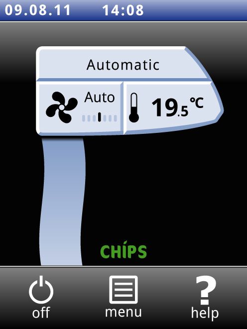
3.4        CHIPS control
                                  The air curtain operates as standard with fully automatic con-
                                  trol. Depending on the selected settings, the air curtain can
                                  also be controlled manually.In automatic mode, the unit oper-
                                  ates under CHIPS control. This control matches the strength
                                  and heat of the air curtain to changing weather conditions.
                                  This reduces energy consumption and improves comfort

Manual version 7.0 (22-04-2013)                                                               en-41
en
     OPERATION                                                                   COMFORT AIR CURTAIN

                                       through selection of the optimum setting under all circum-
                                       stances. CHIPS stands for “Corrective Heat and Impulse Pre-
                                       diction System”. The operation of the air curtain is based on
                                       the outside temperature and the room temperature near the
                                       air curtain.

                                       3.4.1 Automatic or manual control

                                       The air curtain has an automatic and a manual mode. These
                                       can be selected by touching the uppermost part of the air cur-
                                       tain icon.When the unit is switched on, it is always in automa-
                                       tic mode. If you wish to operate the unit only in manual mode,
                                       switch off the automatic mode via menu > Settings > 1. Select
                                       modes.

                                       3.4.2 Recommended setting of the air curtain

                                       To obtain the maximum separation effect and the greatest
                                       comfort possible with the least possible energy consumption,
                                       Biddle recommends use of the fully automatic CHIPS control.

     3.5     Adjusting the strength of the air curtain

                                       3.5.1 Adjusting the automatic strength control

                                       In automatic mode, the strength and temperature of the air
                                       stream are controlled automatically. Due to weather condi-
                                       tions, you might want to adjust the automatic setting. If you
                                       feel a cold draught along the floor, you can increase the auto-
                                       matic strength.

                                                 Note:
                                        n        The adjustment of the automatic strength is not
                                                 always directly translated into a different fan speed.

                                       3.5.2 Manual setting of the strength

                                       With the manual setting, you have 6 strengths to choose from.
                                       To achieve maximum climate separation with minimum energy
                                       consumption, Biddle recommends selecting the lowest
                                       strength at which no draught occurs. This setting may need to
                                       be changed during the day.

     en-42
en
CA2 MANUAL                                                                              OPERATION

3.6        Controlling the temperature
                                   You can set the temperature to a comfortable level. This is the
                                   temperature at the air curtain.With units connected to a Dai-
                                   kin system (CA2 V and CA2 Q), the temperature control is
                                   less accurate than with water or electric heating.
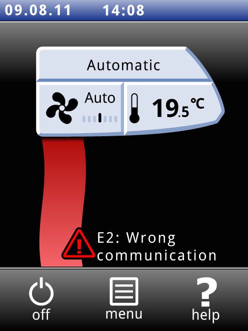
3.7        Faults
                                   The symbol ä indicates that there is a fault. The fault mes-
                                   sage is displayed alongside.

                                   •   Touch this message for further information on the fault and
                                       for instructions as to how to react.

                                             Warning:
                                   w         Some faults may cause damage or danger for
                                             persons if they are disregarded. If ä is
                                             displayed, follow the instructions as to how to
                                             react shown on the operating panel.

                                             Note:
                                   n         The symbol ä and the fault message remain
                                             displayed as long as the fault has not been remedied.

                                   If a fault has remedied itself, a corresponding message will be
                                   displayed. Touch this message to display the and to read out
                                   the last five faults and the times of their occurrence. This list
                                   can also be read out by touching menu > Maintenance > Error
                                   history.

3.8        Main menu
                                   Touch menu to call up the main menu. Here you can set up a
                                   number of frequently occurring functions and make settings in
                                   sub-menus to adapt the function of the air curtain to your spe-
                                   cific situation.

                                   •   Touch home to return to the Home screen again.
                                   •   v and x allow you to scroll through the list.

                                   If the control panel is not operated for some time, it returns
                                   automatically to the Home screen without saving the changes.

Lock the screen                    Select Lock screen to prevent unauthorised access. The # icon
                                   appears on the screen.

Manual version 7.0 (22-04-2013)                                                               en-43
en
     OPERATION                                                                     COMFORT AIR CURTAIN

                                        Unlocking

                                        Touch the screen for 5 seconds to unlock.

     Switching the heating on and off   The heating of the air curtain can be switched on and off man-
                                        ually. This can be useful in summertime when no heating is
                                        necessary.

                                        Switching the heating off disables the room temperature con-
                                        trol.

                                        This function can be deactivated via setting 89 in the configu-
                                        ration menu.

                                        •   Select Heating

                                        When the heating is switched off, the air stream is displayed in
                                        blue.

                                        The heating can also be switched off by the control itself:

                                        •   by an external signal at the input of the unit, see
                                            menu > Configuration > 60. Function of input, setting
                                            Heating off;
                                        •   when the outdoor temperatuur is higher than the setting
                                            of function 84. Heating off temperature.

     Filter                             Dirty filters reduce the effectiveness of the air curtain. It is
                                        therefore necessary to clean or replace the filters at regular
                                        intervals. The filter contamination is either measured with the
                                        optional filter sensor or calculated.

                                        With the optional filter sensor, the unit measures the filter
                                        contamination every 24 hours by running at the highest fan
                                        speed for 40 seconds. You can set the check time for this in
                                        the menu.

                                                  Warning:
                                        w         The default check time is 00:00 h (midnight).
                                                  Be aware that objects can be put into motion
                                                  by the airflow of the air curtain. This might
                                                  set off an alarm system in the building at
                                                  night time.

                                        The cleaning interval can be adjusted to match the actual con-
                                        tamination of the filters.

                                        Without filter sensor the service life of the filter is calculated
                                        in relation to the use of the air curtain. You can adjust this by
                                        setting the maximum service life of the filter.

     en-44
en
CA2 MANUAL                                                                             OPERATION

                                  When the filters are contaminated or when the maximum ser-
                                  vice life is reached, a message appears on the Home screen.

                                  You may clean the filter with, for instance, a vacuum cleaner.
                                  After some cleanings, however, the filter must be replaced.
                                  New filters are available from Biddle.

Cleaning the display              Using the touch screen may cause finger prints or smudges on
                                  the display. The display can be cleaned using a soft, damp cloth.

Timer                             The b-touch control panel has a week timer. You can set two
                                  start and stop times for every day of the week. The unit is on
                                  between the start time and the stop time. The second start
                                  and stop times are optional.When the button ON/OFF is dis-
                                  played on the screen, the unit can also be switched ON or
                                  OFF manually. From the next switching moment the unit then
                                  follows the timer again.When the timer is switched on, the @
                                  icon is displayed in the blue bar of the Home screen.

3.9        Preferences

Preferences                       The menu Preferences allows you to make settings for the use
                                  of the control panel.

Set language                      The control panel offers a choice of languages. Choose your
                                  preferred language from the list.

Set date and time                 The date and time are necessary for the timer function and in
                                  order to track usage statistics of the unit.

                                            Let op:
                                  c         A correct dateis also needed when there is no out-
                                            door or contact sensor connected to the unit. In
                                            this case the CHIPS control estimates the outdoor
                                            temperature based on the month of the year and cli-
                                            mate data for your country. Having a wrong date
                                            causes a less optimal working of the air curtain.

                                  The automatic summer time function switches the clock to
                                  summer or winter time according to the applicable European
                                  rules. If you do not use this function, you can switch to sum-
                                  mer time manually. The clock is then set one hour forward.

Manual version 7.0 (22-04-2013)                                                              en-45
en
     OPERATION                                                            COMFORT AIR CURTAIN

     Temperature unit             Choose between temperature display in degrees Celsius and
                                  degrees Fahrenheit.

     Display brightness           Set the brightness of the display to your personal preferences
                                  or to the specific situation.

     Show tips                    The control panel can show tips about the usage of the unit.
                                  The display of these tips can be enabled or disabled.

     3.10     Settings
                                  The menu Settings allows you to make setting which influence
                                  the day-to-day use of the unit.

     1. Select modes              The operating panel offers various operating modes. The func-
                                  tion Select modes allows you to choose which of these modes
                                  can be selected on the HOME screen.

     5. Room temperature          The default room temperature is the temperature setting at
                                  every start-up of the unit.

                                  This can be overruled manually.

     6. Minimum air temperature   Set the minimum difference between the room temperature
                                  and the discharge temperature.

                                  This difference can be increased for more comfort. A small dif-
                                  ference saves energy.

     8. Night temperature         The night temperature is used when the unit is off. When the
                                  room temperature drops below this setting, the unit will start
                                  working to keep the room on the night temperature.

                                           Warning:
                                  w        Be aware that objects can be put into motion
                                           by the airflow of the air curtain. This might
                                           set off an alarm system in the building at
                                           night time.

     9. Calibration               An unfavourable position of the operating panel or using the
                                  temperature sensor in the air curtain can be the reason why
                                  the temperature displayed differs from the real temperature.

                                  Use this function to adjust the temperature reading.

     en-46
en
CA2 MANUAL                                                                              OPERATION

3.11       Configuration
                                  The menu Configuration allows you to make settings to adjust
                                  the operation of the unit to the room and the system. Usually,
                                  this menu is used only for installation, maintenance and ser-
                                  vice purposes.

50. Access control                Access to the whole control panel or only to the menu can be
                                  protected with a four-digit PIN code.

                                  The default PIN code is 0000.

51. Indoor sensor                 Both the unit and the operating panel have a sensor which
                                  measures the indoor temperature. Choose one that the sys-
                                  tem is to use:

                                  •   Select the sensor on the unit for automatic control. This is
                                      the standard setting.
                                  •   Select the sensor on the control panel if you also wish to
                                      use the air curtain for heating the room. In this case com-
                                      fort may be reduced by draughts along the floor.

52. Display on/off button         The unit can be switched on and off manually. It can also be
                                  switched on and off via the internal timer or via an external
                                  release signal at the input of the operating panel or of the unit.
                                  In this case you can disable the manual switching on and off.
                                  The on/off button is then not displayed on the Home screen.

53. Control panel input           The control panel has one input signal interface. This can be
                                  used for an external of/offsignal or for an additional tempera-
                                  ture sensor.

                                  When the timer is in use, the on/off function of the input of
                                  the control panel is deactivated, irrespective of this setting.

                                  If an additional temperature sensor is connected, this takes
                                  over the function of the sensor in the control panel.

                                            Note:
                                  n         Selecting “Temperature“ without actually connecting
                                            a sensor will lead to a fault message.

54. Strength with door closed     Set the minimum fan speed when contact is made with the
                                  input. Use a door switch here to reduce the fan speed when
                                  the door is closed.This has an effect only when function 60.
                                  Function of input is set to Quick speed up or Slow speed up.

Manual version 7.0 (22-04-2013)                                                               en-47
en
     OPERATION                                                                                                COMFORT AIR CURTAIN

                                                                   If this function is set to zero (fans off), it can occur that the
                                                                   fans start working with the doors closed. This is to maintain
                                                                   the room temperature. If you don’t want this:

                                                                   •   decrease the set room temperature, or:
                                                                   •   change this function to a value other than zero.

     55. Boost function                                            If there is a large difference between the desired and the actual
                                                                   room temperature, the fan speed can be increased to reach
                                                                   the desired temperature quicker.

                                                                   Use this function when the air curtain also is used for heating
                                                                   the room.

                                                                   If 61a/b. Function of output 1/2 is set to value Winter door
                                                                   setting, a contact on that output is also made when the actual
                                                                   difference is larger than this setting.

     58. Maximum strength                                          The maximum fan speed can be limited in order to limit the
                                                                   noise level. This function has an effect only in Automatic
                                                                   mode.

                                                                   Use of this function can reduce the comfort.

     59. Sensor X82                                                The sensor connected to terminal X82 on the unit can act as
                                                                   either an outdoor sensor or as a pipe sensor on the supply
                                                                   pipe of the central heating system. This sensor is used in the
                                                                   automatic control of the air curtain.

                                                                   Pipe sensor

                                                                   The outdoor temperature is derived from the water tempera-
                                                                 ture. For this you need a pipe sensor on the supply pipe of the
     6XSSO\WHPSHUDWXUH

                                          7HPSHUDWXUH            central heating system and a weather depended control of the
                                                                 central heating system.
         ZDWHU>ƒ&@

                                                                 The outdoor temperature is based on the heating curve of the
                                       7HPSHUDWXUH               supplied water. This curve is defined by three points of out-
                                                                 door temperature and water temperature.
                                 7HPSHUDWXUH
                                                                  The first point is for the high outdoor temperature, the last
                                                     
                                                                   point for the low outdoor temperature. Make sure that the
                                 2XWGRRUWHPSHUDWXUH>ƒ&@          limits of all temperatures correspond to the temperatures that
                                                                   can occur.

                                                                   As this is only an estimation, the working of the air curtain
                                                                   might be less optimal.

     en-48
You can also read