GGU-LATPILE Analysis and design of laterally loaded piles - VERSION 9 - GGU-Software
←
→
Page content transcription
If your browser does not render page correctly, please read the page content below
Analysis and design of laterally loaded piles

GGU-LATPILE
                                                         VERSION 9

Last revision:                                                 April 2021
Copyright:                                     Prof. Dr.-Ing. Johann Buß
Technical implementation, layout and sales:   Civilserve GmbH, Steinfeld
Contents:
1 Preface .................................................................................................................................. 6
2 Licence protection................................................................................................................ 7
3 Language selection............................................................................................................... 7
4 Starting the program ........................................................................................................... 8
5 First steps using a worked example.................................................................................... 9
5.1 General note ..................................................................................................................... 9
5.2 System description ........................................................................................................... 9
5.3 Step 1: Select analysis options ....................................................................................... 10
5.4 Step 2: Enter system data ............................................................................................... 11
5.5 Step 3: Define berm on the active side........................................................................... 12
5.6 Step 4: Define berm on the passive side......................................................................... 12
5.7 Step 5: Define soils ........................................................................................................ 13
5.8 Step 6: Define type of earth pressure ............................................................................. 14
5.9 Step 7: Define active earth pressure ............................................................................... 15
5.10 Step 8: Define passive earth pressure............................................................................. 16
5.11 Step 9: Define subgrade reaction modulus profile ......................................................... 17
5.12 Step 10: Analyse system ................................................................................................ 18
5.13 Step 11: Evaluate and visualise the results..................................................................... 23
6 Theoretical principles ........................................................................................................ 25
6.1 General ........................................................................................................................... 25
6.2 Soil properties ................................................................................................................ 26
6.3 Active earth pressure...................................................................................................... 26
6.4 At-rest earth pressure ..................................................................................................... 26
6.5 Increased active earth pressure....................................................................................... 27
6.6 Passive earth pressure .................................................................................................... 27
6.7 Berms ............................................................................................................................. 28
6.8 Area loads....................................................................................................................... 29
6.9 Loads with limited plan dimensions............................................................................... 30
6.10 Bounded surcharges (active side)................................................................................... 31
6.11 Bounded surcharges (passive side) ................................................................................ 32
6.12 2nd order theory .............................................................................................................. 33
6.13 Analysis of mobilised passive earth pressure................................................................. 36
6.14 Analysis of vertical capacity .......................................................................................... 36
7 Description of menu items................................................................................................. 37
7.1 File menu........................................................................................................................ 37
7.1.1 "New" menu item................................................................................................... 37
7.1.2 "Load" menu item .................................................................................................. 39
7.1.3 "Save" menu item .................................................................................................. 39
7.1.4 "Save as" menu item .............................................................................................. 39
7.1.5 "Print output table" menu item............................................................................... 39
7.1.5.1 Selecting the output format ........................................................................... 39
7.1.5.2 Button "Output as graphics".......................................................................... 40
7.1.5.3 Button "Output as ASCII"............................................................................. 42
GGU-LATPILE User Manual Page 2 of 97 April 20217.1.6 "Export" menu item ............................................................................................... 43
7.1.7 "Output preferences" menu item............................................................................ 43
7.1.8 "Print and export" menu item ................................................................................ 43
7.1.9 "Batch print" menu item ........................................................................................ 46
7.1.10 "Exit" menu item.................................................................................................... 46
7.1.11 "1, 2, 3, 4" menu items........................................................................................... 46
7.2 Editor 1 menu................................................................................................................. 47
7.2.1 "Analysis options" menu item................................................................................ 47
7.2.2 "System input" menu item ..................................................................................... 47
7.2.3 "Berms (active side)" menu item ........................................................................... 48
7.2.4 "Berms (passive side)" menu item ......................................................................... 48
7.2.5 "Soils" menu item .................................................................................................. 49
7.2.6 "Type of earth pressure" menu item ...................................................................... 51
7.2.7 "Active earth pressure" menu item ........................................................................ 52
7.2.8 "Passive earth pressure" menu item ....................................................................... 53
7.2.9 "At-rest earth pressure" menu item........................................................................ 54
7.2.10 "User-defined earth pressure coefficients" menu item........................................... 54
7.2.11 "Seismic acceleration" menu item ......................................................................... 55
7.2.12 "Analysis of Sum V" menu item............................................................................ 56
7.2.13 "Partial factors + Sum V" menu item..................................................................... 57
7.3 Editor 2 menu................................................................................................................. 58
7.3.1 "Subgrade reaction moduli" menu item ................................................................. 58
7.3.2 "Displacement boundary conditions" menu item................................................... 59
7.3.3 "Action boundary conditions" menu item.............................................................. 59
7.3.4 "Lateral pressures" menu item ............................................................................... 60
7.3.5 "Area loads" menu item ......................................................................................... 61
7.3.6 "Bounded surcharges" menu item.......................................................................... 62
7.3.7 "Steel sections" menu item .................................................................................... 62
7.3.8 "Differing sections" menu item.............................................................................. 65
7.3.9 "Young's modulus/Specific weight" or "Specific weight" menu items ................. 65
7.4 System menu .................................................................................................................. 66
7.4.1 "Info" menu item ................................................................................................... 66
7.4.2 "Special preferences" menu item ........................................................................... 66
7.4.3 "Depth subdivisions" menu item ........................................................................... 66
7.4.4 "Analyse" menu item ............................................................................................. 67
7.4.5 "Optimise" menu item............................................................................................ 69
7.4.6 "Design defaults" menu item ................................................................................. 70
7.4.7 "Graph positioning preferences" menu item.......................................................... 72
7.4.8 "Graphics output preferences" menu item ............................................................. 73
7.4.9 "Labelling preferences" menu item........................................................................ 74
7.4.10 "Graph grid preferences" menu item ..................................................................... 74
7.4.11 "Dimension lines" menu item ................................................................................ 75
7.4.12 "Display system" menu item.................................................................................. 75
7.4.13 "Display results" menu item .................................................................................. 75
GGU-LATPILE User Manual Page 3 of 97 April 20217.5 Evaluation menu............................................................................................................. 76
7.5.1 "Main output summary" menu item....................................................................... 76
7.5.2 "Maximum reaction summary" menu item ............................................................ 76
7.5.3 "Sum V analyses" menu item................................................................................. 76
7.5.4 "Working capacity" menu item.............................................................................. 77
7.5.5 "Move section bases" menu item ........................................................................... 77
7.6 Graphics preferences menu ............................................................................................ 78
7.6.1 "Refresh and zoom" menu item ............................................................................. 78
7.6.2 "Zoom info" menu item ......................................................................................... 78
7.6.3 "Legend font selection" menu item........................................................................ 78
7.6.4 "Pen colour and width" menu item ........................................................................ 78
7.6.5 "Mini-CAD toolbar" and "Header toolbar" menu items ........................................ 79
7.6.6 "Toolbar preferences" menu item .......................................................................... 79
7.6.7 "General legend" menu item.................................................................................. 81
7.6.8 "Soil properties legend" menu item ....................................................................... 82
7.6.9 "Design legend" menu item ................................................................................... 83
7.6.10 "Subgrade modulus legend" menu item................................................................. 83
7.6.11 "Section legend" menu item................................................................................... 83
7.6.12 "p-y curves legend" menu item.............................................................................. 84
7.6.13 "Move objects" menu item..................................................................................... 85
7.6.14 "Save graphics preferences" menu item................................................................. 85
7.6.15 "Load graphics preferences" menu item ................................................................ 85
7.7 Page size + margins menu .............................................................................................. 86
7.7.1 "Auto-resize" menu item........................................................................................ 86
7.7.2 "Manual resize (mouse)" menu item...................................................................... 86
7.7.3 "Manual resize (editor)" menu item....................................................................... 86
7.7.4 "Font size selection" menu item............................................................................. 86
7.7.5 "Page size and margins" menu item....................................................................... 87
7.7.6 "Undo" menu item ................................................................................................. 88
7.7.7 "Restore" menu item .............................................................................................. 88
7.7.8 "Preferences" menu item........................................................................................ 88
7.8 Info menu ....................................................................................................................... 88
7.8.1 "Copyright" menu item .......................................................................................... 88
7.8.2 "GGU on the web" menu item ............................................................................... 88
7.8.3 "GGU support" menu item..................................................................................... 88
7.8.4 "Maxima" menu item ............................................................................................. 88
7.8.5 "Compare earth pressure coefficients" menu item................................................. 89
7.8.6 "kh method" menu item ......................................................................................... 89
7.8.7 "M-N diagram" menu item .................................................................................... 89
7.8.8 "Steel design to EC3" menu item........................................................................... 89
7.8.9 "Help" menu item .................................................................................................. 89
7.8.10 "What's new?" menu item...................................................................................... 89
7.8.11 "Language preferences" menu item ....................................................................... 89
GGU-LATPILE User Manual Page 4 of 97 April 20218 Tips and tricks.................................................................................................................... 90
8.1 "?" buttons...................................................................................................................... 90
8.2 Keyboard and mouse...................................................................................................... 91
8.3 Function keys ................................................................................................................. 92
8.4 "Copy/print area" icon.................................................................................................... 93
9 Index.................................................................................................................................... 94
List of Figures:
Figure 1 Subgrade reaction modulus profile ...................................................................................6
Figure 2 Worked example ................................................................................................................9
Figure 3 Visualisation of results ....................................................................................................23
Figure 4 Berms on the active side..................................................................................................28
Figure 5 Area load.........................................................................................................................29
Figure 6 At-rest earth pressure from area loads ...........................................................................30
Figure 7 Bounded surcharge (active side).....................................................................................31
Figure 8 Bounded surcharge (passive side)...................................................................................32
Figure 9 Embedded pile.................................................................................................................34
Figure 10 Pile with a displacement boundary condition (wx = 0) ................................................34
Figure 11 Pile with two displacement boundary conditions..........................................................35
GGU-LATPILE User Manual Page 5 of 97 April 20211 Preface
GGU-LATPILE allows analysis and design of piles subjected to lateral loads and moments. For
analysis both the partial safety factors to EC 7 and the global safety factors to DIN 1054 (old)
may be taken into consideration. Subgrade reaction moduli can be applied to user-defined, linearly
variable sections over the length of the pile. By thus dividing the pile into several sections it is
possible to model any subgrade reaction modulus profile.
M(g/q) = -15.0 / 0.0
H(g/q) = -20.0 / 0.0
2.00
25.0 GW (2.00)
10.0
3.00
15.0
50.0
2.50
75.0
SR moduli
Figure 1 Subgrade reaction modulus profile
Elastic analysis supplies the soil stress determined from the product of the subgrade reaction
modulus and the deformation along the length of the pile. This elastic stress must not exceed
the passive earth pressure that can be developed in front of the pile. By means of iteration,
GGU-LATPILE reduces the subgrade reaction modulus such that this condition is adhered to.
GGU-LATPILE calculates both passive (various methods of analysis can be selected) and active
earth pressures.
The Code of Practice published by Forschungsgesellschaft für Straßen- und Verkehrswesen
(FGSV): M EBGS-Lsw - Code of Practice for the Design and Analysis of Footings and Steel
Posts for Noise Abatement Walls and Bird Overfly Aids on Roads (Edition 2018, FGSV no. 552)
has been incorporated for the purposes of analysing noise abatement walls.
As an alternative to the subgrade reaction modulus method, you can also perform a pile analysis
using the p-y method.
GGU-LATPILE User Manual Page 6 of 97 April 2021The application is designed to allow simple data input or modification. The input is immediately
shown on the screen, giving you optimum control over what you are doing. Reading of the manual
can mostly be dispensed with, because
"?" buttons
dealing with almost all geotechnical and program-specific problems are available in the dialog
boxes. You are presented with the necessary information by clicking the "?" button (see also
Section 8.1).
Graphics output supports the true-type fonts supplied with WINDOWS, so that excellent layout is
guaranteed. Colour output and any graphics (e.g. files in formats BMP, JPG, PSP, TIF, etc.) are
supported. PDF and DXF files can also be imported by means of the integrated Mini-CAD mod-
ule (see the "Mini-CAD" manual).
The program has been thoroughly tested. No faults have been found. Nevertheless, liability for
completeness and correctness of the program and the manual, and for any damage resulting from
incompleteness or incorrectness, cannot be accepted.
2 Licence protection
GGU software is provided with the WIBU-Systems CodeMeter software protection system. For
this purpose, the GGU-Software licences are linked to an USB dongle, the WIBU-Systems
CmStick, or as CmActLicense to the respective PC hardware.
It is required for licence access that the CodeMeter runtime kit (CodeMeter software protection
driver) is installed. Upon start-up and during running, the GGU-LATPILE program checks that a
licence on a CmStick or as CmActLicense is available.
3 Language selection
GGU-LATPILE is a bilingual program. The program always starts with the language setting
applicable when it was last ended.
The language preferences can be changed at any time in the "Info" menu, using the menu item
"Spracheinstellung" (for German) or "Language preferences" (for English).
GGU-LATPILE User Manual Page 7 of 97 April 20214 Starting the program
After starting the program, you will see two menus at the top of the window:
File
Info
By going to the "File" menu, a previously analysed system can be loaded by means of the "Load"
menu item, or a new one created using "New". After clicking the "New" menu item a dialog box
opens for specifying general preferences for your new system. You leave the dialog box clicking
on the button with the desired pile type (e.g. "Steel pile").
You then arrive at the initial program screen, containing an example system with legends and the
selected pile type. Now eight menus appear at the top of the window:
File
Editor 1
Editor 2
System
Evaluation
Graphics preferences
Page size + margins
Info
After clicking one of these menus, the so-called menu items roll down, allowing you access to all
program functions.
The program works on the principle of What you see is what you get. This means that the screen
presentation represents, overall, what you will see on your printer. In the last consequence, this
would mean that the screen presentation would have to be refreshed after every alteration you
make. For reasons of efficiency and as this can take several seconds for complex screen contents,
the GGU-LATPILE screen is not refreshed after every alteration.
If you would like to refresh the screen contents, press either [F2] or [Esc]. The [Esc] key addi-
tionally sets the screen presentation back to your current zoom, which has the default value 1.0,
corresponding to an A3 format sheet.
GGU-LATPILE User Manual Page 8 of 97 April 20215 First steps using a worked example
5.1 General note
When using the program for the first time you should enter data starting at the left and then work
through the menu items in sequence from top to bottom. Begin at menu item "Editor 1/Analysis
options" and click each menu item in the "Editor 1" menu, just to get an overview of the multi-
tude of options available in the program. Proceed in analogy for the "Editor 2" menu. Once you
have worked through these two menus you have completely described the system. Details on the
definition of certain input parameters are described in Section 7 pp. An example will describe
procedure more closely.
5.2 System description
As a worked example, the following system is to be analysed:
2.00 1.00 1.00 2.25
10 kN/m²
M(g/q) = -15.0 / 0.0
1.30
H(g/q) = -20.0 / 0.0
1.00
1.00
25.0 GW (2.00)
10.0
3.00
15.0
50.0
2.50
75.0
SR moduli
1.00
Figure 2 Worked example
The system contains three different soils. On the active side is a berm with a surcharge of 10
kN/m². On the passive side is a further berm. The subgrade reaction modulus profile is presented
graphically. A steel pile (HEB 300) is to be analysed. A moment of 15 kN m and a horizontal load
of 20 kN acts on the pile head. The effective direction of the load can be seen in Figure 2.
Groundwater is 2.0 m below the pile head. The pile is 7.5 m long.
GGU-LATPILE User Manual Page 9 of 97 April 20215.3 Step 1: Select analysis options
After starting the program, the logo is displayed. Select the menu item "File/New". A dialog box
will appear where you can define basic preferences of your system.
Enter the values shown in the above dialog box and click "Steel pile". A new system is displayed
on the screen and the complete menu bar is activated.
GGU-LATPILE User Manual Page 10 of 97 April 20215.4 Step 2: Enter system data
Go to the menu item "Editor 1/ System input" and enter the data for the pile head loading.
The pile width is required for determination of the spatial passive earth pressure. Using this menu
item you also enter any groundwater level and distributed loads (see Section 7.2.2).
GGU-LATPILE User Manual Page 11 of 97 April 20215.5 Step 3: Define berm on the active side
Go to the "Editor 1" menu and select "Berms (active side)":
Click "0 berm(s) to edit" and enter 1 as the new number of berms. Enter the following values and
click "Done".
5.6 Step 4: Define berm on the passive side
Go to the "Editor 1" menu and select "Berms (passive side)". Click "0 berm(s) to edit" and enter
the number 1. Enter the following values and click "Done".
GGU-LATPILE User Manual Page 12 of 97 April 20215.7 Step 5: Define soils
Go to the "Editor 1" menu and select "Soils". Click the "Edit no. of soils" button and enter 3 as
new number of soils. Enter the values shown in the following dialog box:
GGU-LATPILE User Manual Page 13 of 97 April 20215.8 Step 6: Define type of earth pressure
Go to the "Editor 1" menu and select "Type of earth pressure".
The necessary buttons are already selected, so you need not change anything. The same applies to
the remaining menu items in "Editor 1". However, you should click on these items and take a
look at them, in order to familiarise yourself with them.
GGU-LATPILE User Manual Page 14 of 97 April 20215.9 Step 7: Define active earth pressure
Go to the "Editor 1" menu and select "Active earth pressure".
If necessary, edit the data there in accordance with the dialog box and confirm with "OK".
GGU-LATPILE User Manual Page 15 of 97 April 20215.10 Step 8: Define passive earth pressure
Go to the "Editor 1" menu and select "Passive earth pressure".
Accept the proposed setting.
GGU-LATPILE User Manual Page 16 of 97 April 20215.11 Step 9: Define subgrade reaction modulus profile
Go to the "Editor 2" menu and select "Subgrade reaction moduli".
Using the "x subgrade moduli to edit" button enter "3" as new number of subgrade reaction
moduli for the example. Edit the values corresponding to the dialog box shown.
GGU-LATPILE User Manual Page 17 of 97 April 20215.12 Step 10: Analyse system
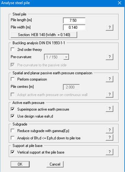
Go to the "System" menu and select "Analyse".
The pile length and pile width were adopted from the "Editor 1/System input" dialog box. If you
would prefer to use a different section, click the "Section: …" button and select the required sec-
tion from the list of sections displayed. Confirm the input by pressing "OK".
EC 7 requires that a verification be performed to demonstrate that the soil stress (ks ꞏ w)d is
smaller than the characteristic passive earth pressure eph,k (not reduced by a partial safety factor!).
However, once analysis is complete it must be verified that the sum of the soil stress is smaller
than the design passive earth pressure:
(ks ꞏ w)d ≤ Eph,k /Ep
GGU-LATPILE User Manual Page 18 of 97 April 2021Using the preferences given so far you will see the following dialog box:
The program has determined that the passive earth pressure is smaller than the resulting soil pres-
sure from the elastic analysis, which is not permitted. An iteration process must be carried out. In
the dialog box shown above, you can enter the iteration conditions. The default values have
proved themselves in practice and will generally not need to be altered.
"Damping" prevents strong fluctuations around the actual solution during the iteration process. A
value of 0.0 produces no damping, while a value of 0.99 produces very strong damping. Using
"Allowable excess > passive" you specify the percentage by which the elastic stress may exceed
the passive earth pressure before the iteration is ended. The "Max. number of iteration steps"
can also be specified. If, after the specified number of steps, compression due to embedding is still
greater than the passive earth pressure, iteration is terminated.
During iteration, the modulus of subgrade reaction is reduced. If the analysis requires a reduction
over the whole length of the pile to a value below "Max. ks", iteration is aborted. This usually
happens when the pile is not long enough to take the load.
When the iteration is complete info boxes appear; use "OK" to close them. You will then see a
prompt for subsequent design; use "Yes" to close it. Then, select the "Find optimum section"
option in the dialog box and confirm by pressing "OK".
GGU-LATPILE User Manual Page 19 of 97 April 2021You will then move directly to the design preferences dialog box (see menu item "System/Design
defaults", Section 7.4.6).
Adopt the data and confirm by pressing "OK". An appropriate message box then opens. The set-
tings given in the box for the optimum section can be adopted:
GGU-LATPILE User Manual Page 20 of 97 April 2021The analysis and design of the pile are complete. The input and results are first displayed in mes-
sage boxes, which you move through by clicking "OK". Because a different section to the origi-
nally selected HEB 300 was designed, the analysis should be repeated using the new HEB 140
section. Adopt the pile width of the newly selected pile by pressing the "Adopt" button and repeat
the analysis and subsequent design of the HEB 140.
When the program starts the Sum V analyses are activated by default (see menu item "Partial
factors + Sum V", Section 7.2.13). Immediately after analyses and design you will therefore see
the following dialog box on analysis of the mobilised passive earth pressure:
Adopt the data and perform the analysis. The results are displayed in a message box. If you exit
the message box by pressing "OK", the editor box analysis of the vertical capacity opens:
GGU-LATPILE User Manual Page 21 of 97 April 2021After accepting the settings by pressing "OK" the data are again displayed in a message box. By
pressing the "Analyse again" button the above dialog box opens again and you can perform the
analysis using the modified data.
GGU-LATPILE User Manual Page 22 of 97 April 20215.13 Step 11: Evaluate and visualise the results
After leaving the info box all governing analysis parameters are displayed on the screen for the
whole pile length:
Figure 3 Visualisation of results
Input subgrade reaction modulus profile,
Computed subgrade reaction modulus profile,
Active and passive earth pressures,
Moment profile,
Shear force profile,
Axial force profile,
Deflection profile.
GGU-LATPILE User Manual Page 23 of 97 April 2021The graphical visualisation, apart from showing the system, also contains other elements (referred
to as legends) which contain further information and user input:
General legend
This legend contains general information on the system.
Soil properties legend
This legend contains data relating to the properties of every defined soil type.
Design legend
This legend contains all data relating to design of steel sections or the cross-section of the
analysed reinforced concrete pile.
Subgrade modulus legend
The legend shows the specified subgrade reaction moduli along the pile section defined for
the subgrade reaction modulus profile.
You can print the diagram on the printer (menu item "File/Print and export", Section 7.1.8), as
well as a comprehensive table of data (menu item "File/Print output table", Section 7.1.5).
Using the program's zoom function, you can zoom in on selected sections of the graphics. If you
double click with the left mouse button over a particular section of the graphics, the corresponding
state variables will appear in an info box.
You can add further explanations or comments to the graphics using the Mini-CAD module. Save
your work to data file by selecting "File/Save as" (Section 7.1.4).
GGU-LATPILE User Manual Page 24 of 97 April 20216 Theoretical principles
6.1 General
GGU-LATPILE solves the differential equation for an elastically embedded pile using the given
boundary conditions.
EJ ꞏ w'''' + kS ꞏ b ꞏ w = q
with
E = Young's modulus
J = moment of inertia
w = pile displacement
kS = subgrade reaction modulus
b = pile width
q = load
The solution is determined numerically using the so-called finite element method.
Action boundary conditions at the pile head can be defined (see menu item "Editor 1/System
input"). At the pile toe, boundary conditions are generally:
Moment = 0.0,
Shear force = 0.0,
Vertical displacement = 0.0.
If you want to define a moment restraint at the pile head, select the "Editor 2/Displacement
boundary conditions" menu item and enter this condition directly below the pile head:
Proceed in a similar manner if, for example, you want to set horizontal displacement to zero (0).
GGU-LATPILE User Manual Page 25 of 97 April 20216.2 Soil properties
A maximum of 50 soil layers can be taken into consideration. The following parameters must be
given for each:
depth in m below pile head, or absolute depth,
unit weight [kN/m³] of the moist soil ,
unit weight [kN/m³] of buoyant soil ',
friction angle [°],
cohesion (active and passive) [kN/m²],
active angle of wall friction as ratio of a/,
passive wall friction angle p/,
cone resistance from CPT qc or cone resistance qb,k,
shear strength of the undrained soil cu,k or skin friction qs,k.
If you activate the "Differentiate active + passive soil properties" check box in the dialog box in
"File/New" or "Editor 1/Analysis options", you can enter differing friction angles and unit
weights for the active and the passive sides.
To analyse the vertical capacity to EAU, EAB and EAP, enter the cone resistance qc and the shear
strength of the undrained soil cu,k. When using empirical data, enter the values for qb,k and qs,k
instead of qc and cu,k.
6.3 Active earth pressure
Active earth pressure is analysed to DIN 4085. DIN 4085 provides two relationships for the
coefficients of earth pressure kah (friction) and kch (cohesion). Alternatively, there is the option of
determining the cohesion coefficient from kch = kah-2, a method often found in older literature.
6.4 At-rest earth pressure
The coefficient of at-rest earth pressure, k0 , is obtained after FRANKE (Die Bautechnik 1974/No.
1) from:
k0 = 1.0 - sin + (cos + sin - 1.0) ꞏ /
= wall friction angle
= ground inclination
The vertical load component resulting from wall friction is obtained from the tangent of the angle
of wall friction. However, in accordance with the EAB, a minimum value of 0.5 ꞏ the horizontal
component is assumed when the tangent of the angle of wall friction is < 0.5.
GGU-LATPILE User Manual Page 26 of 97 April 20216.5 Increased active earth pressure
The coefficient of increased active earth pressure, keh , is obtained from the coefficients of active
earth pressure and at-rest earth pressure:
keh = (1.0 - f) ꞏ kah + f ꞏ k0
0.0 f 1.0
6.6 Passive earth pressure
The coefficient of passive earth pressure can be analysed using a number of methods:
DIN 4085:2017,
DIN 4085:2017 planar slip surfaces,
Streck
Caquot/Kerisel,:p,
DIN 4085:2017 planar slip surfaces/ Caquot/Kerisel,
Culmann / Vogt,
Culmann.
The earth pressure after Culmann is acquired by varying the slip surface angle (see (sheet wall)
Piling Handbook 1977). The forces at the earth pressure wedge are calculated using a slice
method.
Following a proposal by Vogt (Dr. N. Vogt, Vorschlag für die Bemessung der Gründung von
Lärmschutzwänden (Proposal for designing the footings of noise abatement walls), Geotechnik
1988, p. 210) a failure system corresponding to the pile width is considered. The friction and co-
hesion forces acting on both sides of the failure system are incorporated in the calculation after
Culmann. This determines a spatial passive earth pressure.
Otherwise, the following options are available for the spatial effect of the passive earth pressure:
To DIN 4085:2011,
To DIN 4085:2011 planar slip surfaces,
To Weißenbach
Without 3D influence.
GGU-LATPILE User Manual Page 27 of 97 April 20216.7 Berms
GGU-LATPILE can handle 10 berms on both the active and the passive sides. The berms can
include surcharges. The effect on earth pressure is taken into consideration according to the Piling
Handbook (Krupp Hoesch Stahl).
Figure 4 Berms on the active side
The following relationships apply for the parameters x and y:
x = kah0 / (kah - kah0) ꞏ a
y = kah0 / (kah - kah0) ꞏ x
eahu = ꞏ dh + surcharge
= unit weight of soil in the berm area
If the angle is greater than , it is assumed that = for analysis. Berms on the passive side are
dealt with in the same manner.
GGU-LATPILE User Manual Page 28 of 97 April 20216.8 Area loads
Up to 10 area loads can be positioned on the active side at any height.
Area load
Possible types of earth eaho =
pressure distribution 3 * eahu
Type
Figure 5 Area load
The slip surface angle for the active earth pressure resulting from the self-weight of the soil is
adopted for analysis compliant to DIN 4085.
cos
ag arctan
sin sin a cos
sin cos a
When there are a number of soil layers, GGU-LATPILE moves from layer to layer applying the
appropriate angles of friction. The type of resulting earth pressure distribution can be defined in 4
different ways.
GGU-LATPILE User Manual Page 29 of 97 April 2021For at-rest pressure, the effects on the pile from area loads are determined using the theory of
elastic half-space. The two load concentration factors "3" and "4" can be taken into consideration
(also see Figure 6).
For over consolidated, cohesive soils use the concentration factor "3" applies, where:
eop = q/ (2 - 1 + cos1 sin2 - cos2 sin2)
For cohesion less soils or non-over consolidated, cohesive soils use the concentration fac-
tor "4" applies, where:
eop = q/4 (sin³2 - sin³1)
Area load
eop profile
Figure 6 At-rest earth pressure from area loads
Regarding the kind of earth pressure, area loads can be defined independent of the global prefer-
ences (see menu item "Editor 1/Type of earth pressure", Section 0).
6.9 Loads with limited plan dimensions
Loads with limited plan dimensions can be reduced compliant with "Piling Handbook" Fig-
ure 4.20 (page 64) or DIN 4085:2017-08 (page 17), see also Section 7.3.5.
GGU-LATPILE User Manual Page 30 of 97 April 20216.10 Bounded surcharges (active side)
Up to 10 bounded surcharges can be positioned at any height on the active side.
HE
p
a
e ah = k ah ꞏ p
Figure 7 Bounded surcharge (active side)
The earth pressure coefficient k is acquired from kah for active earth pressure and from k0 for at-
rest earth pressure. If this option is activated, the resulting earth pressure is then redistributed.
If negative values are entered, e.g. in order to generate a double-bounded surcharge, the linear
component between and may not be adopted.
GGU-LATPILE User Manual Page 31 of 97 April 20216.11 Bounded surcharges (passive side)
Up to 10 bounded surcharges may be adopted at any height on the passive side. The passive earth
pressure is computed as follows:
p =10.0
p
e ph = k ph ꞏ p
Figure 8 Bounded surcharge (passive side)
GGU-LATPILE User Manual Page 32 of 97 April 20216.12 2nd order theory
The differential equation for a normal flexural member is:
.
The normal force N is taken into consideration for a buckling member:
.
Analysis is performed on the deformed system. In
DIN EN 1993-5
Design of Steel Structures,
Part 5: Piling
analysis using 2nd order theory is recommended for analysis of piles under buckling loads and
DIN EN 1993-1-1
Design of Steel Structures,
Part 1-1: General Rules and Rules for Buildings
referred to. Analysis using 2nd order theory produces more accurate results than the usual and
simplified equivalent member method. Analysis of piles under buckling loads is performed in
GGU-LATPILE compliant with DIN EN 1993-1-1.
Analysis using 2nd order theory requires a predeformation or pre-curvature of the underlying sys-
tem. Pre-curvature values are given in Table 5.1 of DIN EN 1993-1-1.
Pre-curvatures are given as a function of the buckling line. In simplification, piles can be analysed
with a pre-curvature of e0,d/L = 1/150.
GGU-LATPILE User Manual Page 33 of 97 April 2021Using embedded piles without additional displacement boundary conditions the deformed system
is defined by an inclination of the pile.
e0,d
L
Figure 9 Embedded pile
Using embedded piles with a horizontal displacement boundary condition (wx = 0), the deformed
system is defined by a linear pre-curvature from the support point to the top of the pile and a para-
bolic pre-curvature between the support points and the foot of the pile.
e0,d
linear
Parabel e0,d / 2
Figure 10 Pile with a displacement boundary condition (wx = 0)
GGU-LATPILE User Manual Page 34 of 97 April 2021The length L is given per field. The procedure for piles with two displacement boundary condi-
tions is shown in Figure 11.
e0,d
linear
Parabel e0,d / 2
Parabel
Figure 11 Pile with two displacement boundary conditions
The settings are defined in GGU-LATPILE in the analysis menu under "System/Analyse".
The size and direction of the pre-curvature can be specified. Whether a pre-curvature towards the
passive side or the active side provides the more unfavourable design values is system-dependent:
the following message will therefore be displayed once analysis begins:
GGU-LATPILE User Manual Page 35 of 97 April 2021You must therefore deactivate the "Pre-curvature to passive side" check box following success-
ful analysis and check, in a new analysis, whether pre-curvature to the active side delivers less
favourable values.
In an analysis using 2nd order theory the necessary iteration process in terms of displacement is
carried out using the design normal force Nd.
Subsequent design is based on a comparison of stresses
σd ≤ fy,k / γM = fy,k / 1,1 = fy,d
The "Example" folder contains 4 GGU-LATPILE files, which deal with the classical Euler cases
1 to 4. If the vertical load V at the pile head is increased slightly using the "Editor 1/System in-
put" menu item and the system analysed, the following error message appears:
The normal force given in the data files thus corresponds to the buckling force determined after
Euler.
6.13 Analysis of mobilised passive earth pressure
Detailed notes on this analysis concept are included in EAU 2012, Section 8.2.5.5, and in the
Recommendations on Piling (2012).
6.14 Analysis of vertical capacity
Detailed notes on this analysis concept are included in EAU 2012, Section 8.2.5.5, and in the
Recommendations on Piling (2012).
GGU-LATPILE User Manual Page 36 of 97 April 20217 Description of menu items
7.1 File menu
7.1.1 "New" menu item
You can enter a new system using this menu item. You will see the following dialog box:
GGU-LATPILE User Manual Page 37 of 97 April 2021You can enter a dataset description ("Project identification") of the problem going to process,
which will then be used in the General legend (see Section 7.6.7)
In the next group box, the radio buttons are used to specify which safety concept to use for analy-
sis and design. The analysis can be carried out using either the subgrade reaction modulus method
or the p-y method. Using the p-y method, you also select the type of load (static or cyclic). Here
you can also activate the earth support analysis.
Additionally, excavation visualisation to the right can be activated, as well as selecting kN/m³ or
MN/m³ as the units for the modulus of subgrade reaction via a drop-down menu. The units can
also be modified directly in the "Editor 2/Subgrade reaction moduli" menu item dialog box (see
Section 7.3.1). If the "Label passive and active sides in graphics" check box is activated, both
sides are labelled at the bottom of the system.
If you select the "Use absolute heights" check box you can enter all depths or heights in m AD
(heights are positive upwards). If you leave this box unselected, the pile head is assumed at 0.0
(height/depth) and all input of layer depths etc. is positive downwards. Thanks to WYSIWYG
there is no danger of using incorrect data, since all input is immediately visible on the screen. In
this example and the following explanations of this manual the check box "Use absolute heights"
is not selected.
If your system uses differing soil properties on the active and the passive sides, activate the
"Differentiate active + passive soil properties" check box in the above dialog box. You will
then be presented with different input columns for entering the active and passive friction angle
and unit weight soil properties in the "Editor 1/Soils" menu item (Section 7.2.5). For better
visualisation you can define the soil colours on the active and the passive sides differently using
the Soil properties legend (see Section 7.6.8).
Below this, a pile inclination between -6° and +6° can be defined. Please read the information
displayed after pressing the "?" button.
In the "Steel design:" group box, you can choose whether a section from the section list loaded by
the program should be selected to design a steel pile, or whether you wish to design a steel pile
with differing sections. If you work with the section list, the search for the optimum section in the
list is performed automatically. The section list is loaded automatically when the program starts.
However, you can expand and edit this list to suit your requirements (see Section 7.3.7). Steel
design should always follow EC 3.
The type of pile to be analysed is specified using the buttons in the lower group box. If you decide
to use a different pile type during a project, simply select the menu item "File/New" and switch to
the new pile type. Previously entered system data is retained!
If you select "Bored pile", subsequent design to EC 2 will assume a circular cross-section. If you
select "Square pile", subsequent design to EC 2 will assume a square cross-section. The informa-
tion regarding "From section list" is irrelevant for "Bored pile", "Unreinf. bored pile" and
"Square pile".
If you have changed to partial safety factor concept in the uppermost group box, you will see a
further dialog box for specifying the partial factors after clicking the required pile type. Using the
"Default values" button, you can accept the partial factors given in DIN 1054:2010 or EC 7 for
the different load cases. The partial factors entered can be edited at any time using the "Edi-
tor 1/Partial factors + Sum V" menu item (see Section 7.2.13).
GGU-LATPILE User Manual Page 38 of 97 April 20217.1.2 "Load" menu item
You can load a file with system data, which was created and saved at a previous sitting, and then
edit the data.
7.1.3 "Save" menu item
You can save data entered or edited during program use to a file, in order to have them available at
a later date, or to archive them. The data is saved without prompting with the name of the current
file. Loading again later creates exactly the same presentation as was present at the time of saving.
7.1.4 "Save as" menu item
You can save data entered during program use to an existing file or to a new file, i.e. using a new
file name. For reasons of clarity, it makes sense to use ".p20" as file suffix, as this is the suffix
used in the file requester box for the menu item "File/Load". If you choose not to enter an exten-
sion when saving, ".p20" will be used automatically. If the current system has been analysed at the
time of saving, the analysis results are saved in the file.
7.1.5 "Print output table" menu item
7.1.5.1 Selecting the output format
You can have a table printed containing the current analysis results. The results can be sent to the
printer or to a file (e.g. for further editing in a word processor). The output contains all informa-
tion on the current state of analysis, including the system data.
You have the option of designing and printing the output table as an annex to your report within
the GGU-LATPILE program. To do this, select "Output as graphics" from the following op-
tions.
If you prefer to easily print or process the data in a different application, you can send them di-
rectly to the printer or save them to a file using the "Output as ASCII" button.
GGU-LATPILE User Manual Page 39 of 97 April 20217.1.5.2 Button "Output as graphics"
If you selected the "Output as graphics" button in the previous dialog box a further dialog box
opens, in which you can define further preferences for result visualisation.
You can define the desired layout for the output tables in various areas of the dialog box. If you
need to add a header or footer (e.g. for page numbering), activate the appropriate check boxes
"With headers" and/or "With footers" and then click on the "Edit" button. You can then edit as
required in a further dialog box. You can save your settings for the graphical output table
presentation in a "Protokoll.pin_ggu" file at the program level so that they are loaded when the
program starts. Using the "Load" button, the output table settings can also be subsequently loaded
into an existing file, including that of another GGU program.
GGU-LATPILE User Manual Page 40 of 97 April 2021Annex 4.1 Output table
Page 1 of 3
Automatic pagination can also be employed here if you work with the placeholders as described.
After closing the dialog box using "OK" the output table is shown page by page on the screen. To
navigate between the pages, use the arrow tools in the toolbar. If you need to jump to a
given page or back to the graphical visualisation, click on the tool. You will then see the
following box:
GGU-LATPILE User Manual Page 41 of 97 April 20217.1.5.3 Button "Output as ASCII"
You can have your analysis data sent to the printer, without further work on the layout, or save it
to a file for further processing using a different program, e.g. a word processing application.
In the dialog box you can define output preferences.
"Output preferences" group box
Using the "Edit" button the current output preferences can be changed or a different printer
selected. Using the "Save" button, all preferences from this dialog box can be saved to a
file in order to have them available for a later session. If you select "GGU-LATPILE.drk"
as file name and save the file in the program folder (default), the file will be automatically
loaded the next time you start the program.
Using the "Page format" button you can define, amongst other things, the size of the left
margin and the number of lines per page. The "Header/footer" button allows you to enter a
header and footer text for each page. If the "#" symbol appears within the text, the current
page number will be entered during printing (e.g. "Page #"). The text size is given in "Pts".
You can also change between "Portrait" and "Landscape" formats.
"Print pages" group box
If you do not wish pagination to begin with "1" you can add an offset number to the check
box. This offset will be added to the current page number. The output range is defined us-
ing "From page no." "to page no.".
"Output to:" group box
Start output by clicking on "Printer" or "File". The file name can then be selected from or
entered into the box. If you select the "Window" button the results are sent to a separate
window. Further text editing options are available in this window, as well as loading, sav-
ing and printing.
GGU-LATPILE User Manual Page 42 of 97 April 20217.1.6 "Export" menu item
The general stability can be simply verified by exporting the data from GGU-LATPILE to GGU-
STABILITY (GGU slope stability application). After clicking this menu item an appropriate file
(".boe") can be generated with the required GGU-STABILITY version status.
7.1.7 "Output preferences" menu item
You can edit output preferences (e.g. swap between portrait and landscape) or change the printer
in accordance with WINDOWS conventions.
7.1.8 "Print and export" menu item
You can select your output format in a dialog box. You have the following options:
"Printer"
allows graphic output of the current screen contents (graphical representation) to the
WINDOWS default printer or to any other printer selected using the menu item
"File/Output preferences". But you may also select a different printer in the following
dialog box by pressing the "Output prefs./change printer" button.
In the upper group box, the maximum dimensions which the printer can accept are given.
Below this, the dimensions of the image to be printed are given. If the image is larger than
the output format of the printer, the image will be printed to several pages (in the above ex-
ample, 4). In order to facilitate better re-connection of the images, the possibility of enter-
ing an overlap for each page, in x and y direction, is given. Alternatively, you also have the
possibility of selecting a smaller zoom factor, ensuring output to one page ("Fit to page"
button). Following this, you can enlarge to the original format on a copying machine, to en-
sure true scaling. Furthermore, you may enter the number of copies to be printed.
GGU-LATPILE User Manual Page 43 of 97 April 2021You can also read